Note : Les descriptions sont présentées dans la langue officielle dans laquelle elles ont été soumises.
CA 02894203 2015-06-05
WO 2014/098919 PCT/US2012/071550
DEEP FORMATION EVALUATION SYSTEMS AND METHODS
BACKGROUND
Modern petroleum drilling and production operations demand a great quantity of
information relating to the parameters and conditions downhole. Such
information typically
includes the location and orientation of the borehole and drilling assembly,
earth formation
properties, and parameters of the downhole drilling environment. The
collection of
information relating to formation properties and downhole conditions is
commonly referred
1.0 to as
"logging", and can be performed during the drilling process itself (hence the
term
"logging while drilling" or "LWD," frequently used interchangeably with the
term
"measurement while drilling" or "MWD").
Various measurement tools exist for use in LWD. One such tool is the
resistivity tool,
which includes one or more antennas for transmitting an electromagnetic signal
into the
formation and one or more antennas for receiving a formation response. When
operated at
low frequencies, the resistivity tool may be called an "induction" tool, and
at high frequencies
it may be called an electromagnetic wave propagation tool. Though the physical
phenomena
that dominate the measurement may vary with frequency, the operating
principles for the tool
are consistent. In some cases, the amplitude and/or the phase of the receive
signals are
compared to the amplitude and/or phase of the transmit signals to measure the
formation
resistivity. In other cases, the amplitude and/or phase of multiple receive
signals are
compared to each other to measure the formation resistivity.
When plotted as a function of depth or tool position in the borehole, the
logging tool
measurements are termed "logs." Such logs may provide indications of
hydrocarbon
concentrations and other information useful to drillers and completion
engineers. In
particular, azimuthally-sensitive logs may provide information useful for
steering the drilling
assembly because they can inform the driller when a target formation bed has
been entered or
exited, thereby enabling modifications to the drilling program that will
provide much more
value and higher success than would be the case using only seismic data.
However, the utility
of such logs is often impaired by the latency between a drill-bit's
penetration of a bed boundary
and the collection of log information sufficient to alert the driller to that
event.
CA 02894203 2015-06-05
WO 2014/098919 PCT/US2012/071550
BRIEF DESCRIPTION OF THE DRAWINGS
A better understanding of the various disclosed embodiments can be obtained
when
the following detailed description is considered in conjunction with the
attached drawings, in
which:
FIG. 1 shows an illustrative logging while drilling (LWD) environment.
FIG. 2A shows an illustrative drillstring with two logging tool modules.
FIG. 2B shows an illustrative drillstring in both straight and bent
configurations.
FIG. 2C shows a projection of an LWD tool module antenna's location.
FIG. 3 shows a block diagram of two logging tool modules and a surface system.
FIG. 4 shows an illustrative azimuthal bin arrangement.
FIG. 5 shows an illustrative method for deep formation evaluation.
FIG. 6 shows three illustrative drillstrings, each with three logging tool
modules.
It should be understood that the drawings and corresponding detailed
description do
not limit the disclosure, but on the contrary, they provide the foundation for
understanding all
modifications, equivalents, and alternatives falling within the scope of the
appended claims.
DETAILED DESCRIPTION
The paragraphs that follow describe illustrative apparatuses, systems and
methods for
producing deep formation evaluations using logging while drilling ("LWD")
tools with
zo multiple modules that may have different orientations relative to each
other. An illustrative
drilling environment suitable for using such apparatuses, systems and methods
is first
described, followed by a description of an illustrative drillstring with two
LWD tool modules.
The positional relationships between antennas housed within the LWD tool
modules are also
described and expressed mathematically, as are the effects of these
relationships on received
signals propagated through the surrounding formation. An illustrative system
and a
software-based method implemented by the system are described that perform
deep
formation evaluation of the surrounding formation based upon the antenna
positions (i.e.,
location and orientation) and received signals. Finally, examples of
embodiments that use
more than two LWD tool modules are described.
2
CA 02894203 2015-06-05
WO 2014/098919 PCT/US2012/071550
The disclosed apparatuses, systems and methods are best understood in the
context of
the larger systems in which they operate. Accordingly, FIG. 1 shows an
illustrative LWD
environment. A drilling platform 2 supports a derrick 4 having a traveling
block 6 for raising
and lowering a drill string 8. A top drive 10 supports and rotates the drill
string 8 as it is
lowered through the wellhead 12. A drill bit 14 is driven by a downhole motor
and/or rotation
of the drill string 8. As bit 14 rotates, it creates a borehole 16 that passes
through various
formations. A pump 18 circulates drilling fluid 20 through a feed pipe 22,
through the interior
of the drill string 8 to drill bit 14. The fluid exits through orifices in the
drill bit 14 and flows
upward through the annulus around the drill string 8 to transport drill
cuttings to the surface,
io where the fluid is filtered and recirculated.
The drill bit 14 is just one piece of a bottom-hole assembly 24 that includes
a mud
motor and one or more "drill collars" (thick-walled steel pipe) that provide
weight and
rigidity to aid the drilling process. Some of these drill collars include
built-in logging
instruments to gather measurements of various drilling parameters such as
location,
orientation, weight-on-bit, borehole diameter, etc. The tool orientation may
be specified in
terms of a tool face angle (rotational orientation), an inclination angle (the
slope), and
compass direction, each of which can be derived from measurements by
magnetometers,
inclinometers, and/or accelerometers, though other sensor types such as
gyroscopes may
alternatively be used. In one specific embodiment, the tool includes a 3-axis
fluxgate
zo magnetometer and a 3-axis accelerometer. As is known in the art, the
combination of those
two sensor systems enables the measurement of the tool face angle, inclination
angle, and
compass direction. Such orientation measurements can be combined with
gyroscopic or
inertial measurements to accurately track tool position.
Also included in bottom-hole assembly 24 is a telemetry sub that maintains a
communications link with the surface. Mud pulse telemetry is one common
telemetry
technique for transferring tool measurements to surface receivers and
receiving commands
from the surface, but other telemetry techniques can also be used. For some
techniques (e.g.,
through-wall acoustic signaling) the drill string 8 includes one or more
repeaters 30 to detect,
amplify, and re-transmit the signal. At the surface, transducers 28 convert
signals between
mechanical and electrical form, enabling a network interface module 36 to
receive the uplink
signal from the telemetry sub and (at least in some embodiments) transmit a
downlink signal
to the telemetry sub. A data processing system 50 receives a digital telemetry
signal,
demodulates the signal, and displays the tool data or well logs to a user.
Software
3
CA 02894203 2015-06-05
WO 2014/098919 PCT/US2012/071550
(represented in FIG. 1 as non-transitory information storage media 52) governs
the operation
of system 50. A user interacts with system 50 and its software 52 via one or
more input
devices 54 and 55 and one or more output devices 56. In some system
embodiments, a driller
employs the system to make geosteering decisions and communicate appropriate
commands
to the bottom-hole assembly 24.
The drillstring shown in FIG. 1 illustrates a directional drilling operation,
wherein
drilling is performed along a path other than a straight vertical path
downward. In at least
some illustrative embodiments, the change in direction is achieved using a
"bent sub," which
is a tubular section along the drillstring near the drill bit that is bent or
curved. The bend or
ro curve may be fixed or variable, with the direction of the drilling being
determined either by
the bend alone, or by a combination of the bend and the rotation of the
drillstring. For
example, if a downhole motor is used to drive the drill bit and a drillstring
with a fixed bent
sub is maintained at a fixed azimuthal orientation, the drill string will
gradually change
direction towards the direction of the bend. If instead such a drillstring is
rotated, drilling will
progress along a line parallel to the drillstring section above the bend and
about which the
drill bit precesses.
For drillstrings capable of varying the angle of the bent sub, the sub is set
to a desired
angle and direction while the drillstring is maintained at a desired fixed
azimuthal orientation,
with the drill bit being driven by the downhole motor. This is sometimes
referred to as "slide
drilling," as the drillstring slides through the borehole without rotating. In
other drillstring
embodiments, the drillstring continues to be rotated and the angle of the bent
sub is
maintained by applying a force on the drillstring in a specific direction.
This causes the sub to
be pushed into the borehole wall opposite the desired drilling direction to
create an angle
between the drillstring pipes and/or bottom-hole assembly units to either side
of the sub. Such
systems are sometimes referred to as rotary steerable systems.
Because of the angle change introduced by the above-described subs and systems
used in directional drilling, and because of the bends produced in the
drillstring by the
resulting borehole, logging tool modules located along the length of the
drillstring may be
oriented in different directions. This is particularly true for logging tools
utilized in deep
formation evaluation (i.e., tools wherein a transmitter antenna is separated
from a receive
antenna by at least 20 feet), as the transmit and receive antennas used in
such tools may be
housed in logging tool modules that are separated by larger distances
(compared to other
logging tools) in order to achieve the desired formation penetration of the
transmitted signals.
4
CA 02894203 2015-06-05
WO 2014/098919 PCT/US2012/071550
The greater the distance between the logging tool modules, the greater the
inclination and
strike angle differences may be between drillstring sections traversing a
borehole path that is
curved or otherwise not a straight line. As used herein, the inclination angle
of an LWD tool
module that houses an antenna is defined as the angle between a vertical z
axis and the
drillstring's z axis local to said antenna. The strike angle is defined as the
angle between a
reference vector normal to a vertical z axis and a projection onto a
horizontal x-y plane of the
drills tring's z axis local to the antenna.
FIG. 2A shows an illustrative embodiment of a deep formation evaluation
logging
tool that includes two LWD tool modules 202 and 206 at different locations and
orientations
io along a drillstring. In the embodiment shown, a resistivity logging tool
receive antenna 212
and a corresponding receive antenna position measurement device 222a are
housed within
LWD tool module 202, while a resistivity logging tool transmit antenna 216 and
a
corresponding transmit antenna position measurement device 222b (components of
an "at
bit" instrument) are housed within LWD tool module 206. The position
measurement devices
locate the position of each corresponding antenna, which may be expressed, for
example, in
terms of each antenna's tilt angle (Or and Ot relative to the Zr and z, axes
respectively;
generally fixed and known), each antenna's azimuthal angle (a, and at relative
to the x axis),
each LWD tool module's inclination angle (Or and Ot) and the distance cl-
between the
antennas. Various methods may be used to locate the antenna positions (e.g.,
relative to a
reference position on the surface), several of which are described in more
detail below. It
should be noted that although the bent sub angles are typically less than five
degrees, the
figures show much more pronounced angles to better illustrate the effect of
the angles on the
relative spatial locations of the antennas, described in more detail below.
The above-described antenna and LWD tool module orientations may be used to
calibrate tool responses prior to performing an inversion process to model the
surrounding
formation. Such calibration is performed in order to be able to compare the
modeled and
measure results, as the modeled results assume known and fixed orientations
and spatial
locations of the resistivity logging tool transmit and receive antennas
relative to each other,
but the measured results may originate from antennas with any of a number of
different
relative orientations and spatial locations other than those presumed in the
model. Measured
and modeled results may be in the form of complex voltages, complex currents,
resistivity
values derived from measured/modeled voltages and/or currents, and/or ratios
of voltages,
currents and/or resistivities, just to name a few examples. Part of this
calibration can be
5
CA 02894203 2015-06-05
WO 2014/098919
PCT/1182012/071550
performed mathematically as one or more matrix rotations, while another part
may be
performed as a derivation of the relative spatial locations of and/or distance
between antennas
based on the antennas' locations and orientations. The resulting calibrated
response is
provided to the inversion, which uses these inputs to model the formation.
Equation (1), expressed more simply in equation (2), illustrates the rotation
portion of
the calibration process, taking into account each of the above-described
angles:
sin(Ot + MO) cos oct (to) T VAto) Vj(t0) KX(to) Sin(Or + Or(to)) COS CrO (to)
VRto) = sin(Ot + (MO) sin cxt (to)
KY(to) VyY(to) KY(to) sin(er + 0,-(to)) sin os. (to) (1)
i
cos(Ot + (t0)) KZ(t) Vyz(to) Vzz(to) cos(0, + Or (to))
=
VAto)= TT lt 1 V . vector ¨0, ' - matrix (to) ' Rvector(to) (2)
where T,Lc,(to) (shown in transposed form for convenience) is given by the
transmit
in antenna's known tilt angle a, and by the inclination angle 0, and
azimuthal angle a, as
determined by the transmit antenna's position measurement device at time to;
Rvector(to) is
given by the receive antenna's known tilt angle 0õ and by the inclination
angle 0, and
azimuthal angle a, as determined by the receive antenna's position measurement
device at
time to; and Vmatr(to) is a 3x3 voltage matrix consisting of nine components
171. Each
component represents a theoretical voltage at a receive antenna with a j axis
orientation (x, y
or z) in response to a signal from a transmit antenna with an i axis
orientation (also x, y or z)
for a given formation model, operating frequency and spacing d'.
Another part of the calibration may involve determining the distance between
the
transmit antenna and the receive antenna. The distance between transmit and
receive antennas
changes when two or more LWD tool modules are positioned such that they no
longer share a
common z axis. For example, in FIG. 2A both LWD tool modules 202 and 206 are
inclined
such that each z axis (Zr and zt) is inclined at a different inclination angle
0 (0, and 0,) relative
to a vertical reference z axis. The inclination angle change reduces the
original distance
between the receive and transmit antennas 212 and 216 from original distance d
when the
drillstring was straight (bent sub 204 set to 0 degrees) to distance d'. This
reduction is
illustrated in FIG. 2B, which shows the drillstring of FIG. 2A in both
straight and bent
configurations, though the reduction can also be the results of flexing of the
drillstring over
long distances through curved and/or irregular boreholes. The distance
reduction can be
significant for high-resolution logging tools, where the difference between d
and d' may be
comparable in magnitude to the resolution of the logging tool. For example,
for a look-ahead
6
CA 02894203 2015-06-05
W02014/098919 PCT/US2012/071550
tool the distance between transmit and receive antennas can be as great as 100
feet, which for
borehole paths with significant bends and/or irregularities can produce, in at
least some
instances, a difference between the original and calibrated distance of more
than 10 feet.
A number of different known techniques may be used to determine a calibrated
distance d'. For example, given a known original distance d between the two
LWD tool
modules of FIG. 2A when they are straight and aligned, d' can be determined by
adjusting the
original distance d using the equation,
d'=d=cos(Ot ¨ Or) (3)
Other, more complex configurations may require different trigonometric and/or
geometric
calculations, and may be based upon absolute rather than relative positions.
For example,
three-dimensional coordinates may describe the locations of a transmit and a
receive antennas
relative to a reference point on the surface, with differences in the x, y and
z coordinates of
each antenna being used to determine the distance d between the two antennas.
Once the
calibrated distance has been calculated, it can be provided together with the
calibrated
modeled response to the inversion process, which determines the model
parameters that
produce a modeled response matching the measured values for transmit and
receive antennas
spaced apart by calibrated distance d', as described in more detail below.
In addition to using distance alone, fully described spatial locations of the
transmit
and receive antennas relative to each other may also be input to the inversion
process to more
accurately match measured responses to modeled responses when compared to
inversions
that do not account for such locations. These relative spatial locations take
into account
displacements along the x-y plane as well as along the z axis. Such
displacements may be
significant factors within formations with anisotropies that can affect how a
signal propagates
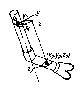
through the formation. FIG. 2C shows an example using Cartesian coordinates to
locate the
lower LWD tool module's antenna relative to a coordinate system centered on
the upper
LWD tool module's antenna. The zp coordinate of the lower antenna is projected
onto the
upper antenna's z axis, and the xp and yp coordinates are first projected onto
the x-y plane, and
then individually onto each corresponding axis. The coordinates thus fully
describe the
relative positions of the two antennas within the formation. It should be
noted that the relative
spatial locations may also be fully described using polar coordinates, i.e.,
in terms of the
distance d' together with the relative LWD tool module inclination and
azimuthal angles.
Thus, calibrated distance d' may be derived from the relative spatial
locations.
7
CA 02894203 2015-06-05
WO 2014/098919 PCT/US2012/071550
FIG. 3 is a block diagram of illustrative electronics for the above-described
LWD tool
modules (202 and 206) and an associated surface system 50 that together form
an illustrative
LWD system 300. Surface system 50 is suitable for collecting, processing and
displaying
logging data via display 56, and in at least some embodiments generates
geosteering signals
from the logging data measurements and displays them to a user. A user may
further interact
with the system via keyboard 54 and pointing device 55 (e.g., a mouse) to send
commands to
the LWD tool modules 202 and 206 to steer the drillstring in response to the
received data. If
desired, surface system 50 can be programmed to send such commands
automatically in
response to logging data measurements, thereby enabling surface system 50 to
serve as an
io autopilot for the drilling process.
Located within surface system 50 is a display interface 352, a telemetry
transceiver
354, a processor 356, a peripheral interface 358, an information storage
device 360, a
network interface 362 and a memory 370. Bus 364 couples each of these elements
to each
other and transports their communications. Telemetry transceiver 354 enables
the surface
system 50 to communicate with the LWD tool modules (either directly or
indirectly), and
network interface 362 enables communications with other systems (e.g., a
central data
processing facility via the Internet). In accordance with user input received
via peripheral
interface 358 and program instructions from memory 370 and/or information
storage device
360, processor 356 processes telemetry information received via telemetry
transceiver 354 to
construct formation property logs in accordance with the disclosed methods
and/or
geosteering signals, and display them to the user.
Surface system 50 communicates with LWD tool module 202, which receives
control
messages from, and provides logging data to, surface system 50 via telemetry
transceiver
302. Controller and memory 304 couples to telemetry transceiver 302, power
source 306,
information storage device 308, one or more position measurement devices 310,
a short hop
telemetry transceiver 312 and one or more receive and/or transmit antennas
314, coordinating
the operation of the various components. In some illustrative embodiments
transmit/receive
antenna(s) 314 receives electromagnetic signals 322 transmitted by LWD tool
module 206
that are used to measure the electrical characteristics of the surrounding
formation. In other
embodiments, controller and memory 304 causes transmit/receive antenna(s) 314
to transmit
electromagnetic signals 324 which are received and measured by LWD tool module
206. The
measurements are communicated by wireless signal 326 from LWD tool module 206
to LWD
tool module 302 via short hop telemetry transceiver 312. The position of
antenna(s) 314
8
CA 02894203 2015-06-05
WO 2014/098919 PCT/US2012/071550
is/are determined by position measurement device(s) 310, and the position and
measurement
information is forwarded to controller and memory 304 for storage within
information
storage device 308, with at least some of this information being communicated
to surface
system 50.
LWD tool module 206 includes a power source 330, controller and memory 332,
position measurement device(s) 334, short hop telemetry transceiver 336 and
transmit/receive
antenna(s) 338, each coupled to each other and operating in a manner similar
to the
corresponding components of LWD tool module 202. In some embodiments, LWD tool
module 206 transmits electromagnetic signals 322 for measurement by logging
tool module
202, while in others LWD tool module 206 receives electromagnetic signals 324
transmitted
by logging tool module 202. LWD tool modules 202 and 206 exchange information
via short
hope telemetry transceivers 312 and 336 that can include electromagnetic
signal
measurements, transmit/receive synchronization signals and configuration and
control
commands. This information may originate from any component within the system,
including
is but not
limited to controller and memory 304 and 332, and surface system 50. The power
sources 306 and 330 used to power the downhole components of LWD tool modules
202 and
206 may include batteries, vibration energy harvesters, turbines, electrical
generators or any
other suitable mechanism. Transmit/receive antennas 314 and 338 may include
any of a
number of antennas, including but not limited to azimuthally sensitive
antennas such as tilted
loop antennas. Short hop telemetry transceivers 312 and 336 may use any
suitable short hop
downhole communications technique. Also, additional sensors (not shown) may
also be
incorporated into each LWD tool module and can include temperature, pressure,
lubrication,
vibration, strain and density sensors to monitor drilling conditions.
Surface system processor 356 and LWD tool module controllers and memories 304
and 332 each generally operates in accordance with one or more programs stored
on an
information storage medium (e.g., information storage device 360). These
programs cause the
controller and/or processing system to carry out at least part of the methods
disclosed herein.
For simplicity, the description of the method that follows assumes that each
of the modules
performing the described functions are all resident within memory 370 and
executed by
processor 356 of surface system 50 (as shown in FIG. 3). Nonetheless, it is
contemplated that
one or more of these functions may be performed by modules resident in memory
within one
of LWD tool modules 202, LWD tool module 206 and/or logging tool 310, and
executed by a
corresponding downhole processor and/or controller. Also, although a system
with one tilted
9
CA 02894203 2015-06-05
WO 2014/098919 PCT/US2012/071550
transmit antenna within LWD tool module 206 and one tilted receive antenna
within LWD
tool module 202 operating at a single frequency is described, it is understood
that any number
of transmit and/or receive antennas operating and one or more frequencies may
be used
within each LWD tool module, and that the described methods may be implemented
by
systems with more than two LWD tool modules.
Before describing the illustrative method of FIG. 5, it is helpful to provide
some
further context. FIG. 4 shows an example of how a borehole can be divided into
azimuthal
bins (i.e., rotational angle ranges). In Fig. 4, the circumference has been
divided into eight
bins numbered 402, 404, ... , 416. Of course, larger or smaller numbers of
bins can be
employed. The rotational angle is measured from the high side of the borehole
(except in
vertical boreholes, where the rotational angle is measured relative to the
north side of the
borehole). As a rotating tool gathers azimuthally sensitive measurements, the
measurements
can be associated with one of these bins and with a depth value. Typically LWD
tools rotate
much faster than they progress along the borehole, so that each bin at a given
depth can be
associated with a large number of measurements. Within each bin at a given
depth, these
measurements can be combined (e.g., averaged) to improve their reliability.
Referring now to the illustrative method and system of FIGS. 3 and 5
respectively, the
number of azimuthal bins is defined (block 502, FIG. 5; binning module 372,
FIG. 3) based
on the number of inclined LWD tool modules, the number of frequencies of the
signals
propagated by the transmit antenna(s) through the formation and the number of
transmit and
receive antennas. In general, for a greater number of inclined LWD tool
modules (i.e., a
greater borehole path complexity), a greater number of bins are needed to
perform an
inversion to determine the formation model. For greater numbers of frequencies
and
antennas, smaller numbers of bins may be used. Thus, for example, a system
operating at a
single frequency that has a single bent sub with one transmitter and one
receiver can require
as few as four azimuthal measurements, while a single frequency system with
one transmitter
and two receivers or two transmitters and one receiver can require as few as
two azimuthal
measurements.
Once the number of bins is defined, electromagnetic signal transmission is
triggered
(e.g., signals 322 from a transmit antenna 338 within LWD tool module 206,
triggered by
transmit module 374; block 504), causing the signals to propagate through the
surrounding
formation to a receive antenna (e.g., receive antenna 314 within LWD tool
module 202),
where the signal is sampled and measured for each azimuthal bin, and further
processed to
CA 02894203 2015-06-05
WO 2014/098919 PCT/ITS2012/071550
produce a measurement (block 504; receive module 376). In at least some
illustrative
embodiments, the measurement represents a deep formation measurement (e.g.,
resistivity,
voltage, current, etc.). Data is concurrently collected from position
measurement devices 310
and 334 for each measurement, which is used in the derivation of antenna
location and
orientation data (block 506; position module 378).
Once the location and orientation data has been derived, the data can be used
to
calculate the transmit and receive vectors T.E. it 1 and R
--vector(t0) of equations (1) and (2) and
the corresponding relative spatial locations of the transmit and receive
antennas (block 508;
calibration module 382). As previously noted, measurements corresponding to a
same index
in (i.e., same borehole position and azimuthal bin) may be aggregated, with
the aggregated data
being used in the above-described calculation. The measurements, relative
spatial locations
and transmit and receive matrices are then indexed by antenna position along
the borehole
and by azimuthal bin and stored on a storage device (block 510; storage module
380), such as
information storage device 360.
The stored indexed data may subsequently be used as input to an inversion
process
that begins with the selection of initial formation model parameters (block
512; inversion
module 384). Such parameters may include, but are not limited to, adjusted
estimated
formation resistivity, anisotropy, dip and bed boundaries. The coupling
component matrix
V551(to) of equations (1) and (2) is computed based on the selected parameters
for formation
zo model 386 and combined with the transmit and receive vectors and the
relative spatial
locations to produce a calibrated modeled response (block 514; inversion
module 382). The
calibrated modeled response is compared with the measured response (block 516;
inversion
module 382) to determine if the responses match. Such a "match" is not
necessarily an exact
match, but may instead be based on an acceptance criteria such, for example,
as a least
squares criteria calculated over a set of values around the full circumference
of the tool and
for a specific depth range. Other acceptance criteria suitable for use with
the disclosed
methods and systems will become apparent to those of ordinary skill in the
art, and all such
criteria are within the scope of the present disclosure.
If the differences between the calibrated model and measured responses does
not fall
within the acceptance criteria (block 518, inversion module 382) different
formation model
parameters are selected (block 520; inversion module 382), and blocks 514
through 518 are
repeated by inversion module 382. Once a match is achieved, the formation
model with the
parameters that produced the match is presented to a user (block 522;
inversion module 382),
11
CA 02894203 2015-06-05
WO 2014/098919 PCT/US2012/071550
for example, as a display indicating the formation composition. If drilling
continues (block
524: inversion module 382), the inversion process continues using the
identified module. If a
mismatch between the modeled and measured responses is identified, the model
parameters
are again changed until a match is found (blocks 514 through 518). The
inversion process
s defined by blocks 514 through 524 continues until drilling completes
(block 524), ending the
method (block 526).
The above-described inversion process uses the relative spatial locations of
the
receive and transmit antennas as an input. This determination of these
relative spatial
locations depends upon an accurate determination of the positions of the
transmit and receive
io antennas, which may include the antennas' locations (e.g., latitude,
longitude and depth,
relative distance to a reference point, etc.) and/or orientations (e.g.,
compass heading, angle
relative to a vertical or horizontal plane, direction towards a reference
point, etc.). In the
above-described embodiments these positions are determined at least in part by
the position
measurement devices 222a and 222b of FIG. 2A. Each position measurement device
may
is include one or more devices, including but not limited to magnetometers,
inclinometers,
accelerometers and gyroscopes. In at least some illustrative embodiments,
these devices
operate together to track their movement relative to a known reference point
at the top of the
borehole as the position measurement device progresses downhole.
In some illustrative embodiments, such as those shown in FIG. 6, one or more
20 position measurement devices 622 transmit one or more very low frequency
signals (e.g., a
1 Hz electromagnetic, seismic or acoustic signal) to, or receive a signal
from, a surface
receiver/transmitter 602. In the left embodiment of FIG. 6, each position
measurement device
622 within LWD tool modules 604, 606 and 608 communicates with surface station
602 to
determine the direction towards each position measurement device or surface
station (e.g.,
25 using a phased array) and the distance between each position measurement
device and the
surface station (e.g., by calculating signal propagation delays).
For clarity, previous embodiments have been described as having position
measurement devices co-located with each antenna that each determines its own
position
relative to an external coordinate system (e.g., a geographical position, a
position relative to a
30 surface location, etc.). In practice, it is the spatial relationships of
the antennas that are
desired, and any tool configuration that provides such relationships may be
used. For
example, in at least some illustrative embodiments a single position
measurement device may
be used that determines the spatial location of each antenna relative to its
own position by
12
CA 02894203 2015-06-05
WO 2014/098919
PCT/1JS2012/071550
=
receiving low frequency signals from transmitters (such as those described
above) that are
each co-located with an antenna. Such a position measurement device can itself
be co-located
with one of the antennas, or not co-located with any of the antennas. The
information needed
to determine the position of each transmitter and thus the corresponding
antenna(s) (e.g.,
distance and angle to the position measurement device) may be derived based on
the
characteristics of the signals received and/or processed by the position
measurement device
(e.g., propagation delay, phase, amplitude, direction, etc.).
The center embodiment of FIG. 6 shows an example of an LWD tool that
determines
relative positions of at least some of the antennas within the tool. In this
example, low
lo frequency transmitter 624 within LWD module 608 and low frequency
transceiver 623 within
LWD module 606 are each co-located with an antenna (not shown). Transmitter
624 provides
a signal to transceiver 623, which determines a relative location and
orientation of transmitter
624 and its corresponding antenna. This information may be forwarded to
position
measurement device 622 for further processing (e.g., using a short hop
communication link as
previously described). Transceiver 623 also transmits a signal received by
position
measurement device 622, which may then determine the position of transceiver
623 relative
to position measurement device 622 based on the received signal. In the right
embodiment
shown in FIG. 6, transmitters 624 within each of LWD tool modules 606 and 608
transmit a
signal received by position measurement device 622 of LWD tool module 604,
which
determines the relative direction and distance to each transmitter. In
embodiments that
calculate relative direction and distance, position measurement device 622
within LWD tool
module 604 determines an absolute reference position using any of the
techniques described
to provide a basis for determining the positions of the antennas within the
LWD tool modules
further downhole. Many other combinations of absolute and relative position
calculations
based on measurements by any of a number of position measurement device
configurations
will become apparent to those of ordinary skill in the art, and all such
calculations and
configurations are within the scope of the present disclosure.
As can be seen from FIG. 6, the use of position measurement devices for each
of
multiple LWD tool modules enables the position of each antenna within each
module to be
tracked even with complex module positioning, enabling a more accurate
determination of
the distance between transmit and receive antennas as compared with systems
and methods
that presume a fixed distance. This can be useful with boreholes with one or
more "doglegs",
where the drilling direction changes several times in several different
directions. The
13
CA 02894203 2015-06-05
WO 2014/098919 PCT/US2012/071550
disclosed systems and methods account for these changes, enabling accurate
calculations of
the distances between transmit and receive antennas along a drillstring while
traversing
complex borehole paths, and thus enabling more accurate deep formation
evaluations of the
surrounding formation when compared to system that presume fixed distances
between the
antennas.
Numerous other modifications, equivalents, and alternatives, will become
apparent to
those skilled in the art once the above disclosure is fully appreciated. For
example, although
FIG. 2A shows an "at bit" LWD tool module separated from the logging tool by a
bent sub,
any number of other separate LWD tool modules positioned at locations along
the cirillstring
io other than adjacent to the drilling bit may alternatively or
additionally be present. Also,
although the illustrative embodiments are shown and described within the
context of
induction and EM resistivity logging tools, other embodiments may
alternatively or
additionally include other logging and measurement tools (e.g., galvanic
resistivity logging
tools). Further, although the rotation portion of the disclosed calibration is
performed by
is rotating the modeled response for comparison to the measured response,
the calibration may
also be performed by rotating the measured response instead prior to the
comparison. It is
intended that the following claims be interpreted to embrace all such
modifications,
equivalents, and alternatives where applicable.
14