Sélection de la langue

Search

Sommaire du brevet 2894727 

Énoncé de désistement de responsabilité concernant l'information provenant de tiers

Une partie des informations de ce site Web a été fournie par des sources externes. Le gouvernement du Canada n'assume aucune responsabilité concernant la précision, l'actualité ou la fiabilité des informations fournies par les sources externes. Les utilisateurs qui désirent employer cette information devraient consulter directement la source des informations. Le contenu fourni par les sources externes n'est pas assujetti aux exigences sur les langues officielles, la protection des renseignements personnels et l'accessibilité.

Disponibilité de l'Abrégé et des Revendications

L'apparition de différences dans le texte et l'image des Revendications et de l'Abrégé dépend du moment auquel le document est publié. Les textes des Revendications et de l'Abrégé sont affichés :

  • lorsque la demande peut être examinée par le public;
  • lorsque le brevet est émis (délivrance).
(12) Brevet: (11) CA 2894727
(54) Titre français: PAVES EN BETON A GRAIN DE BOIS
(54) Titre anglais: WOOD GRAIN CONCRETE PAVING SLABS
Statut: Périmé et au-delà du délai pour l’annulation
Données bibliographiques
Abrégés

Abrégé français

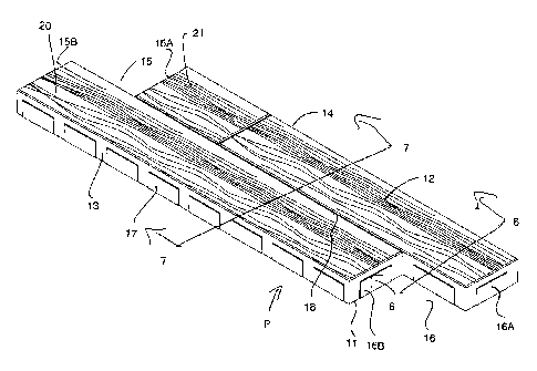
Un ensemble de pavés en béton moulés est couché dans un motif côte à côte et de bout en bout pour couvrir une zone à paver. Chacun des éléments de pavés possède des butées despacement latérales et dextrémité pour maintenir un élément de pavé adjacent à un espacement prédéterminé. Chacun des pavés possède une fente longitudinale dans la surface supérieure qui définit un faux joint parallèle aux côtés de manière à diviser la surface supérieure en bandes parallèles. Il existe différents types de pavés, certains avec les deux bandes divisées par des fentes transversales et certains avec seulement une bande avec une fente. Ceci forme dans les pièces de bande apparentes de produit fini de nombreuses longueurs différentes pour simuler des planches de bois. Chacune des bandes parallèles possède une surface supérieure moulée qui définit une série de lignes ondulées renfoncées par rapport aux autres parties de la surface supérieure et colorées plus foncées que la partie restante du pavé, simulant ainsi une apparence de grain de bois.


Abrégé anglais


A set of cast concrete paving slabs is laid in a pattern side by side and
end to end to cover an area to be paved. Each of the slabs members has side
and
end spacer abutments to hold an adjacent slab member at a predetermined
spacing.
Each of the slabs has a longitudinal slot in the upper surface defining a
false joint
parallel to the sides so as to divide the upper surface into parallel strips.
There are
different types of slabs some with both strips divided by transverse slots and
some
with only one strip with a slot. This forms in the finished product apparent
strip
pieces of many different lengths to simulate wood planks. Each of the parallel
strips
has a molded upper surface defining a series of wavy lines recessed from other
parts of the upper surface and dyed darker than the remaining part of the slab
thus
simulating a wood grain appearance.

Revendications

Note : Les revendications sont présentées dans la langue officielle dans laquelle elles ont été soumises.


10
CLAIMS:
1. A set of
cast concrete paving slabs arranged to be laid in a
pattem to cover an area to be paved, the set of slabs comprising:
a plurality of slab members;
each slab member having a bottom surface for laying in the area and
an upper surface for presenting for viewing when laid;
each slab member having a first side, a second side parallel to the first
side, a first end and a second end;
the slab members being arranged to be laid side by side and end to
end to cover the area;
each of the slab members having spacer abutments attached thereto
at the sides and ends so as to hold an adjacent slab member at a predetermined
spacing to form a spaced joint therebetween;
each of the slab members having at least one slot in the upper surface
defining a false joint and extending along the length of the slab member
parallel to
the sides so as to divide the upper surface into a plurality of parallel
strips;
each of the parallel strips having a molded upper surface defining a
series of wavy lines recessed from other parts of the upper surface and
simulating a
wood grain appearance;
wherein only the recessed wavy lines contain a dye in the concrete
which is different from and contrasting from that in the other parts of the
upper
surface.

11
2. The set of paving slabs according to claim 1 wherein each slab
member consists of a single longitudinal slot defining two parallel strips.
3. The set of paving slabs according to claim 1 or 2 wherein the
parallel strips have first ends .at the first end of the slab member which are
longitudinally offset.
4. The set of paving slabs according to claim 3 wherein the parallel
strips have second ends at the second end of the slab member which are
longitudinally offset by a distance equal to a distance of the offset of the
first ends.
5. The set of paving slabs according to claim 3 wherein the parallel
strips of each of the slab members of the set have first ends at the first end
of the
slab member which are longitudinally offset and have second ends at the second
end of the slab member which are longitudinally offset by a distance equal to
a
distance of the offset of the first ends and equal to the distance of all the
other slab
members of the set.
6. The set of paving slabs according to any one of claims 1 to 5
wherein at least one of the strips of at least one of the set has at least one
slot in the
upper surface defining a false joint and extending transverse to the length of
the slab
member at right angles to the sides so as to divide the upper surface into a
plurality
of end to end strips.
7. The set of paving slabs according to any one of claims 1 to 5
wherein each of the strips of at least one of the set has at least one slot in
the upper
surface defining a false joint and extending transverse to the length of the
slab

12
member at right angles to the sides so as to divide the upper surface into a
plurality
of end to end strips.
8. The set of paving slabs according to any one of claims 1 to 5
wherein each of the slab members of the set has two parallel strips wherein
one of
the strips of at least one of the set has one slot in the upper surface
defining a false
joint and extending transverse to the length of the slab member at right
angles to the
sides so as to divide the upper surface into a plurality of end to end strips
and
wherein both of the strips of at least one other of the set has one slot in
the upper
surface defining a false joint and extending transverse to the length of the
slab
member at right angles to the sides so as to divide the upper surface into a
plurality
of end to end strips.
9. The set of paving slabs according to any one of claims 1 to 8
wherein the simulated wood grain appearance of each of the strips of each of
the
slab members of the set has a pattern which is different from the others.
10. The set of paving slabs according to any one of claims 1 to 9
wherein the recessed wavy lines have a depth of recess from the remainder of
the
upper surface which is in the range 0.1mm to 2.75mm.
11. A set of cast concrete paving slabs arranged to be laid in a
pattern to cover an area to be paved, the set of slabs comprising:
a plurality of slab members;
each slab member having a bottom surface for laying in the area and
an upper surface for presenting for viewing when laid;

13
each slab member having a first side, a second side parallel to the first
side, a first end and a second end;
the slab members being arranged to be laid side by side and end to
end to cover the area;
each of the slab members having spacer abutments attached thereto
at the sides and ends so as to hold an adjacent slab member at a predetermined
spacing to form a spaced joint therebetween;
each of the slab members having at least one longitudinal slot in the
upper surface defining a false joint and extending along the length of the
slab
member parallel to the sides so as to divide the upper surface into a
plurality of
parallel strips;
each of the parallel strips having a molded upper surface defining a
series of wavy lines recessed from other parts of the upper surface and
simulating a
wood grain appearance;
wherein each of the slab members consist of a single longitudinal slot
defining only two parallel strips;
wherein each of the slab members of the set are arranged such that
the two parallel strips have first ends at the first end of the slab member
which are
longitudinally offset and have second ends at the second end of the slab
member
which are longitudinally offset by a distance equal to a distance of the
offset of the
first ends and equal to the distance of all the other slab members of the set;

14
wherein some of the slab members of the set has in each of the two
parallel strips thereof a slot in the upper surface defining a false joint and
extending
transverse to the length of the parallel strip at right angles to the sides so
as to
divide the upper surface the strip into a plurality of end to end strip
portions;
wherein some of the slab members of the set has in only one of the
two parallel strips thereof a slot in the upper surface defining a false joint
and
extending transverse to the length of the parallel strip at right angles to
the sides so
as to divide the upper surface the strip into a plurality of end to end strip
portions so
that the other of the two parallel strips has no transverse slot and forms a
continuous
single strip.
12. The set of paving slabs according to claim 11 wherein the
simulated wood grain appearance of each of the strips of each of the slab
members
of the set has a pattern which is different from the others.
13. The set
of paving slabs according to claim 11 or 12 wherein the
recessed wavy lines have a depth of recess from the remainder of the upper
surface
which is in the range 0.1 mm to 2.75 mm.

Description

Note : Les descriptions sont présentées dans la langue officielle dans laquelle elles ont été soumises.


CA 02894727 2016-08-23
1
WOOD GRAIN CONCRETE PAVING SLABS
This invention relates to cast concrete paving slabs and to a set of
paving slabs which can be laid in a pattern to provide a wood grain
appearance.
SUMMARY OF THE INVENTION
According to the invention there is provided a set of cast concrete
paving slabs arranged to be laid in a pattern to cover an area to be paved,
the set of
slabs comprising:
a plurality of slab members;
each slab member having a bottom surface for laying in the area and
an upper surface for presenting for viewing when laid;
each slab member having a first side, a second side parallel to the first
side, a first end and a second end;
the slab members being arranged to be laid side by side and end to
end to cover the area;
each of the slab members having spacer abutments attached thereto
at the sides and ends so as to hold an adjacent slab member at a predetermined
spacing to form a spaced joint therebetween;
each of the slab members having at least one slot in the upper surface
defining a false joint and extending along the length of the slab member
parallel to
the sides so as to divide the upper surface into a plurality of parallel
strips;

CA 02894727 2016-08-23
2
each of the parallel strips having a molded upper surface defining a
series of wavy lines recessed from other parts of the upper surface and
simulating a
wood grain appearance;
wherein only the recessed wavy lines contain a dye in the concrete
which is different from and contrasting from that in the other parts of the
upper
surface.
Preferably each of the slab members of the set has only two parallel
strips but embodiments are possible in which more than two strips are
provided.
Preferably the recessed wavy lines contain a dye in the concrete which
is different from that in the other parts of the upper surface. This provision
of a dye
material absorbed into the concrete at the recessed lines which is typically
darker
than the remainder of the concrete slab provides an effective simulation of
the wood
grain. That is the different dye in the recessed wavy lines is provided only
in the
recessed wavy lines so that the remainder of the paving slabs is of a common
color.
Preferably the parallel strips have first ends at the first end of the slab
member which are longitudinally offset and preferably the parallel strips have
second
ends at the second end of the slab member which are longitudinally offset by a
distance equal to a distance of the offset of the first ends. This provides
symmetrical
arrangements which can be fitted together in different patterns.
Preferably, in an arrangement in which each of the slab members has
only two strips, one of the strips of one or more of the set has a slot in the
upper
surface defining a false joint and extending transverse to the length of the
slab

CA 02894727 2016-08-23
3
member at right angles to the sides so as to divide the upper surface into a
plurality
of end to end strips.
Also preferably in this arrangement both of the strips of at least one
other of the set has a slot in the upper surface defining a false joint and
extending
transverse to the length of the slab member at right angles to the sides so as
to
divide the upper surface into a plurality of end to end strips.
Preferably the simulated wood grain appearance of each of the strips
of each of the slab members of the set has a pattern which is different from
the
others.
Preferably the recessed wavy lines have a depth of recess from the
remainder of the upper surface which is in the range 0.1mm to 2.75mm.
According to a second aspect of the invention there is provided a set of
cast concrete paving slabs arranged to be laid in a pattern to cover an area
to be
paved, the set of slabs comprising:
a plurality of slab members;
each slab member having a bottom surface for laying in the area and
an upper surface for presenting for viewing when laid;
each slab member having a first side, a second side parallel to the first
side, a first end and a second end;
the slab members being arranged to be laid side by side and end to
end to cover the area;

CA 02894727 2016-08-23
4
each of the slab members having spacer abutments attached thereto
at the sides and ends so as to hold an adjacent slab member at a predetermined
spacing to form a spaced joint therebetween;
each of the slab members having at least one longitudinal slot in the
upper surface defining a false joint and extending along the length of the
slab
member parallel to the sides so as to divide the upper surface into a
plurality of
parallel strips;
each of the parallel strips having a molded upper surface defining a
series of wavy lines recessed from other parts of the upper surface and
simulating a
wood grain appearance;
wherein each of the slab members consist of a single longitudinal slot
defining only two parallel strips;
wherein each of the slab members of the set are arranged such that
the two parallel strips have first ends at the first end of the slab member
which are
longitudinally offset and have second ends at the second end of the slab
member
which are longitudinally offset by a distance equal to a distance of the
offset of the
first ends and equal to the distance of all the other slab members of the set;
wherein some of the slab members of the set has in each of the two
parallel strips thereof a slot in the upper surface defining a false joint and
extending
transverse to the length of the parallel strip at right angles to the sides so
as to
divide the upper surface the strip into a plurality of end to end strip
portions;

CA 02894727 2016-08-23
wherein some of the slab members of the set has in only one of the
two parallel strips thereof a slot in the upper surface defining a false joint
and
extending transverse to the length of the parallel strip at right angles to
the sides so
as to divide the upper surface the strip into a plurality of end to end strip
portions so
5 that the other of the two parallel strips has no transverse slot and
forms a continuous
single strip.
BRIEF DESCRIPTION OF THE DRAWINGS
One embodiment of the invention will now be described in conjunction
with the accompanying drawings in which:
Figure 1 is a top plan view of a first single cast concrete paving slab of
a set of such slabs according to the invention.
Figure 2 is a top plan view of a second single cast concrete paving
slab of the set of such slabs.
Figure 3 is a top plan view of a third single cast concrete paving slab of
the set of such slabs.
Figure 4 is a top plan view of a fourth single cast concrete paving slab
of the set of such slabs.
Figure 5 is an isometric view of the concrete slab of Figure 1.
Figure 6 is a cross-sectional view along the lines 6-6 of Figure 5.
Figure 7 is a cross-sectional view along the lines 7-7 of Figure 5.
Figure 8 is a top plan view of the set of the paving slabs of Figures 1,

CA 02894727 2016-08-23
6
2, 3 and 4 laid over an area to be covered and showing the interaction between
the
slabs.
In the drawings like characters of reference indicate corresponding
parts in the different figures.
DETAILED DESCRIPTION
In figures 1 to 4 is shown the four slabs of a set of cast concrete paving
slabs arranged to be laid in a pattern to cover an area to be paved. In Figure
8 the
slabs of Figures 1 to 4 are shown laid in patterns where the different shapes
combine to provide a pleasing effect as described in more detail hereinafter.
The
slabs are shown in plan view in Figures 1 to 4 and 8 so that the various
shapes of
the slabs can be readily determined.
The construction of the slabs is better shown in Figures 5, 6 and 7
where each slab 10 has a bottom surface 11 for laying in the area and an upper
surface 12 for presenting for viewing when laid. Each slab has a first side
13, a
second side 14 parallel to the first side, a first end 15 and a second end 16
so that
the slab can be laid side by side and end to end to cover the area to be
covered by
the pattern of slabs.
Each of the slabs has a series of rectangular spacer abutments 17 cast
into the sides so as to be attached thereto along the sides and ends so as to
contact
the abutment of an adjacent slab and hold the adjacent slab member at a
predetermined spacing to form a spaced joint therebetween. The abutments are

CA 02894727 2016-08-23
7
recessed from the top surface 12 and form a layer of constant thickness on the
side
or end surface of the slab.
Each of the slab members has a longitudinal slot cast into the upper
surface defining a false joint and extending along the length of the slab
member
parallel to the sides 13 and 14 so as to divide the upper surface into a pair
of parallel
strips 20 and 21. The slot 18 mimics the space between two of the slabs as
defined
by the spacer abutments so that the depth of the slot is approximately equal
to the
spacing of the abutments from the top surface and the width of the slot is
constant
and approximately equal to the thickness of the two abutting abutments.
Each of the slabs is arranged so that the two parallel strips have first
ends 15A and 15B of the strips 20 and 21 at the first end 15 of the slab
member
which are longitudinally offset and symmetrically the second ends 16A and 16B
at
the second end 16 are longitudinally offset by a distance equal to a distance
of the
offset of the first ends. These longitudinal offsets are the same at the ends
of the
same slab and are equal to the distance of all the other slabs of the set.
In addition, at least one of the strips of each of the set of slabs shown
in Figures 1 to 4 has at least one slot in the upper surface defining a false
joint and
extending transverse to the length of the slab member at right angles to the
sides so
as to divide the upper surface into a plurality of end to end strips. Thus the
slab of
Figure 1 has a slot 25 in the strip 20 and the strip 21 is continuous. Thus
the slab of
Figure 2 has a slot 26 in the strip 21 and the strip 20 is continuous.

CA 02894727 2016-08-23
8
In Figures 3 and 4, each of the strips 20 and 21 has one slot 27, 28,
29, 30 in the upper surface defining a false joint and extending transverse to
the
length of the slab member at right angles to the sides so as to divide the
upper
surface into two end to end strips. It will be noted by comparing the four
figures that
the slot 25 is spaced from the end 15A by a different distance than the slot
26 from
the end 15B. Also the slots 29 and 30 are spaced from the ends 15A and 16B by
a
different distance than the slots 27 and 28. This arrangement forms the strip
portions defined by these false joints to be of different lengths, which
provides a very
varied appearance in the finished assembly as shown in Figure 8. Thus in
Figure 8
the four above defined slabs are used in various location through the layout
with
each of the four marked by shading.
Each of the parallel strips of the slabs has a molded upper surface
defining a series of wavy lines 40 recessed from other parts of the upper
surface and
simulating a wood grain appearance. The recessed wavy lines as they simulate
the
lines in wood grain form an array of generally parallel peaks 41 and valleys
42 where
the valleys 42 are recessed from the surface 12.
The cast concrete contains a dye which colors it as close as possible
to the brown wood color and the concrete material in the peaks 41 contains a
dye 43
in the concrete which is different from the dye 44 in the other parts of the
upper
surface. Typically the dye 44 extends through the whole of the slab. Typically
the
dye 43 in the recessed wavy lines 40 is colored in contrast to that of the
other parts,
which could be lighter or darker. The different dye 43 in the recessed wavy
lines is

CA 02894727 2016-08-23
9
provided only in the concrete in the area of the recessed wavy lines 40 so
that the
remainder of the paving slabs is of a common color.
As shown in Figures 1 to 4, the simulated wood grain appearance of
each of the strips of each of the slab members of the set has a pattern which
is
different from that of the others. Thus when assembled as shown in Figure 8,
the
different lengths of the strips and the different patterns in the strips
provides a
particularly attractive appearance particularly effectively simulating the
appearance
of a wood floor.
In order to provide an effective wood grain appearance, the recessed
wavy lines have a depth of recess from the remainder of the upper surface
which is
in the range 0.1mm to 2.75mm.

Dessin représentatif
Une figure unique qui représente un dessin illustrant l'invention.
États administratifs

2024-08-01 : Dans le cadre de la transition vers les Brevets de nouvelle génération (BNG), la base de données sur les brevets canadiens (BDBC) contient désormais un Historique d'événement plus détaillé, qui reproduit le Journal des événements de notre nouvelle solution interne.

Veuillez noter que les événements débutant par « Inactive : » se réfèrent à des événements qui ne sont plus utilisés dans notre nouvelle solution interne.

Pour une meilleure compréhension de l'état de la demande ou brevet qui figure sur cette page, la rubrique Mise en garde , et les descriptions de Brevet , Historique d'événement , Taxes périodiques et Historique des paiements devraient être consultées.

Historique d'événement

Description Date
Le délai pour l'annulation est expiré 2022-03-01
Lettre envoyée 2021-06-18
Lettre envoyée 2021-03-01
Lettre envoyée 2020-08-31
Inactive : COVID 19 - Délai prolongé 2020-08-19
Inactive : COVID 19 - Délai prolongé 2020-08-06
Inactive : COVID 19 - Délai prolongé 2020-07-16
Inactive : COVID 19 - Délai prolongé 2020-07-02
Inactive : COVID 19 - Délai prolongé 2020-06-10
Représentant commun nommé 2019-10-30
Accordé par délivrance 2016-11-08
Inactive : Page couverture publiée 2016-11-07
Inactive : Taxe finale reçue 2016-09-27
Préoctroi 2016-09-27
Inactive : Page couverture publiée 2016-09-26
Un avis d'acceptation est envoyé 2016-09-16
Lettre envoyée 2016-09-16
Inactive : Approuvée aux fins d'acceptation (AFA) 2016-09-14
Inactive : Q2 réussi 2016-09-14
Lettre envoyée 2016-08-29
Toutes les exigences pour l'examen - jugée conforme 2016-08-23
Modification reçue - modification volontaire 2016-08-23
Avancement de l'examen jugé conforme - PPH 2016-08-23
Requête d'examen reçue 2016-08-23
Avancement de l'examen demandé - PPH 2016-08-23
Exigences pour une requête d'examen - jugée conforme 2016-08-23
Demande publiée (accessible au public) 2016-08-23
Inactive : CIB attribuée 2015-08-16
Inactive : CIB en 1re position 2015-08-16
Inactive : CIB attribuée 2015-08-16
Exigences de dépôt - jugé conforme 2015-06-26
Inactive : Certificat dépôt - Aucune RE (bilingue) 2015-06-26
Demande reçue - nationale ordinaire 2015-06-22
Inactive : CQ images - Numérisation 2015-06-18
Inactive : Pré-classement 2015-06-18

Historique d'abandonnement

Il n'y a pas d'historique d'abandonnement

Historique des taxes

Type de taxes Anniversaire Échéance Date payée
Taxe pour le dépôt - générale 2015-06-18
Requête d'examen - générale 2016-08-23
Taxe finale - générale 2016-09-27
TM (brevet, 2e anniv.) - générale 2017-06-19 2017-03-28
TM (brevet, 3e anniv.) - générale 2018-06-18 2018-03-15
TM (brevet, 4e anniv.) - générale 2019-06-18 2019-03-18
Titulaires au dossier

Les titulaires actuels et antérieures au dossier sont affichés en ordre alphabétique.

Titulaires actuels au dossier
BARKMAN CONCRETE LTD.
Titulaires antérieures au dossier
WAYNE PATRAM
Les propriétaires antérieurs qui ne figurent pas dans la liste des « Propriétaires au dossier » apparaîtront dans d'autres documents au dossier.
Documents

Pour visionner les fichiers sélectionnés, entrer le code reCAPTCHA :


Pour visualiser une image, cliquer sur un lien dans la colonne description du document. Pour télécharger l'image (les images), cliquer l'une ou plusieurs cases à cocher dans la première colonne et ensuite cliquer sur le bouton "Télécharger sélection en format PDF (archive Zip)" ou le bouton "Télécharger sélection (en un fichier PDF fusionné)".

Liste des documents de brevet publiés et non publiés sur la BDBC .

Si vous avez des difficultés à accéder au contenu, veuillez communiquer avec le Centre de services à la clientèle au 1-866-997-1936, ou envoyer un courriel au Centre de service à la clientèle de l'OPIC.


Description du
Document 
Date
(aaaa-mm-jj) 
Nombre de pages   Taille de l'image (Ko) 
Description 2015-06-18 7 230
Abrégé 2015-06-18 1 21
Dessins 2015-06-18 8 172
Revendications 2015-06-18 3 101
Description 2016-08-23 9 289
Revendications 2016-08-23 5 159
Abrégé 2016-08-23 1 22
Dessin représentatif 2016-08-29 1 30
Page couverture 2016-09-26 1 62
Dessin représentatif 2016-10-28 1 33
Page couverture 2016-10-28 1 60
Certificat de dépôt 2015-06-26 1 187
Accusé de réception de la requête d'examen 2016-08-29 1 176
Avis du commissaire - Demande jugée acceptable 2016-09-16 1 164
Rappel de taxe de maintien due 2017-02-21 1 111
Avis du commissaire - Non-paiement de la taxe pour le maintien en état des droits conférés par un brevet 2020-10-19 1 548
Courtoisie - Brevet réputé périmé 2021-03-29 1 540
Avis du commissaire - Non-paiement de la taxe pour le maintien en état des droits conférés par un brevet 2021-07-30 1 542
Nouvelle demande 2015-06-18 3 75
Correspondance 2016-09-27 2 53