Note : Les descriptions sont présentées dans la langue officielle dans laquelle elles ont été soumises.
CA 02895570 2015-06-18
WO 2014/102125
PCT/EP2013/077259
DEVICE FOR GENERATING A DYNAMIC AXIAL THRUST TO BALANCE
THE OVERALL AXIAL THRUST OF A RADIAL ROTATING MACHINE
The invention relates to radial rotating machines, such as centrifugal
compressors
or single stage fluid expanders.
Generally speaking, a radial rotating machine may be a rotating machine for
processing a fluid flow, the fluid flow being forced to flow radially at least
along
part of the flow path.
A radial rotating machine is a rotating machine for processing a fluid flow,
in
which the fluid flow occurs radially at least along part of the flow path. The
radial
rotating machine may be for instance a centrifugal compressor.
Centrifugal compressors or single stage expanders are radial rotating
machines:
they comprise bladed impeller wheels, which are designed to force the fluid
flow
radially away from the axis of the rotating machine.
These impeller wheels are subjected to axial forces which may be of two types:
so-called static axial forces, which are generated by the difference in fluid
pressure
between the upstream side and the downstream side of the wheel,
and so-called dynamic axial forces, which are a result of the momentum change
imposed to the fluids, flowing in axially into the impeller wheel, and coming
out
radially out of the wheel.
These axial forces are usually partly balanced by balance drum systems, and
partly
balanced by axial thrust bearings, for instance by oil bearings.
In said balance drum systems, at least a balance drum part is assembled around
the
same shaft as the impeller wheel. The balance drum part comprises two radially
extending surfaces, facing opposite axial directions, and subjected to
different fluid
pressures.
1
CA 02895570 2015-06-18
WO 2014/102125
PCT/EP2013/077259
These balance drum systems usually are tuned to counterbalance for static
axial
forces.
According to their design, balance drum systems can sometimes also
counterbalance for part of the dynamic axial forces. The remainder of axial
forces
then has to be counterbalanced with axial thrust bearings. Axial thrust
bearings
may be of different types. Oil bearings are capable of withstanding high
loads, but
they have to be fed with the lubricating oils, which may be a hindrance in
subsea
applications, because of a lack of accessibility of the system, or in medical
applications, where contamination by oil cannot be tolerated.
Depending on the maximum axial forces that the thrust bearing can withstand,
and
depending on the proportion of axial forces not counterbalanced by the balance
drum, the fluid throughput of the machine has to be limited, to a value
generally
lower than the maximum throughput imposed by the other parameters of the
radial
rotating machine.
The invention aims at proposing an impeller wheel system which ensures a
better
axial force compensation, thus making it possible to use bearings of only the
magnetic type. Another aim of the invention is to reduce the overall length
and
mass of the system.
To this purpose, an impeller wheel assembly according to the invention, for a
radial
rotating machine, comprises a bladed hub portion of an impeller wheel, with a
first,
radially outward facing fluid deflecting surface having a curvature profile
designed
to deflect an axial fluid flow into a radial centrifugal flow. The impeller
wheel
assembly comprises a deflector portion with a second radially outward facing
fluid
deflecting surface. The second radially outward facing surface has a curvature
profile designed to deflect a radial centripetal fluid flow into an axial
fluid flow,
and is placed axially downstream, considering the direction of the axial fluid
flows,
of the first radially outward facing surface. The first, radially outward
facing
surface supports a plurality of blades of the bladed hub portion.
2
CA 02895570 2015-06-18
WO 2014/102125
PCT/EP2013/077259
According to the invention, a radial rotating machine for processing a fluid,
comprises one or more impeller wheels attached to a same shaft, each with a
bladed
hub portion, each bladed hub portion comprising a first radially outward
facing,
fluid deflecting surface having a curvature profile designed to deflect an
axial fluid
flow into a radial centrifugal flow. The machine also comprises:
- a shroud assembled around each hub portion so as to trap an axial fluid
flow
reaching the bladed hub portion and so as to force the fluid flow along the
first
outward facing surface,
- a stator including a guiding passage for a fluid coming from between the
shrouds
and the first outward facing surfaces, the passage comprising after each
impeller
wheel, a centrifugal diffuser portion followed by a bend, then followed by a
centripetal return channel portion.
The machine comprises at least a deflector portion with a second radially
outward
facing, fluid deflecting surface, inserted into the fluid flow path, rotating
together
with the shaft, and having a curvature profile designed to deflect a radial
centripetal
fluid flow into an axial fluid flow. The machine comprises the same number of
deflector portions inserted into the fluid flow path, as the total number of
impeller
wheel attached to the shaft.
A deflector portion may be placed upstream of a bladed hub portion.
A deflector portion may also be placed downstream of a bladed hub portion.
A deflector portion and a bladed hub portion may belong to a same impeller
wheel
part.
An impeller wheel assembly may comprise a rotor shaft, and may comprise a hub
part defining a least part of the first outward facing surface, and a
deflector part
defining at least part of the second outward facing surface, both hub part and
deflector part being assembled to the shaft so as to transmit both axial and
rotational forces to the shaft.
3
CA 02895570 2015-06-18
WO 2014/102125
PCT/EP2013/077259
The shaft may have a variable section so that the surface of the shaft defines
a
portion of either the first or the second outward facing surface.
The first outward facing surface and the second outward facing surface may
each
be defined by a globally concave surface, the concavity of each of the two
surfaces
facing opposite axial directions.
An impeller wheel assembly may comprise a first seal portion surface placed
axially between the bladed hub portion and the deflector portion, the second
outward facing surface extending from the most downstream side of the second
outward facing surface, up to the first seal portion surface, by surface
portions
which are all oriented either radially, or facing radially outwards.
A second outward facing surface may comprise a central surface portion which
comprises an axial surface portion, or a central surface portion which comes
tangent to an axial direction.
A second outward facing surface may be limited by a radially outer surface
portion
which comprises an axial surface portion, or by a radially outer surface
portion
which comes tangent to a radial plane, the whole outward facing surface
extending
axially downstream of the radial plane.
When a deflector portion is placed upstream of a hub portion, a resulting
impeller
wheel assembly may be assembled in axial overhang to the shaft. The bladed hub
portion is then next to the shaft and the deflector portion is on the axial
side
opposite to the shaft.
In an embodiment, at least a portion of a return channel is delimited by the
second
outward facing surface.
The radial rotating machine may comprise a first seal bridging a gap between
the
stator and the impeller wheel assembly, the first seal being at an axial
position
between the first outward facing surface and the second outward facing
surface,
and may comprise a second seal around the shroud, bridging a gap between the
shroud an a stator part.
4
CA 02895570 2015-06-18
WO 2014/102125
PCT/EP2013/077259
In some embodiments, the first seal is placed radially on the outside of the
first
outward facing surface, along a circumferential outer edge of the impeller
wheel
assembly.
In other embodiments, the first seal and the second seal extend roughly at a
same
radial distance from the axis of the shaft. One can consider the first seal
and the
second seal extend approximately at a same radial distance if the average
radii of
the two seals surfaces belonging to the impeller and to the shroud, differ of
no more
than 10%, and preferably no more than 5%.
In the radial rotating machine, viewed in a radial plane, the angles between
the
centrifugal fluid flow leaving the first outward facing surface, and fluid
flows along
the second outward facing surface remain less than 180 . To achieve this, the
first
and second outward facing surfaces are so configured that, viewed in a radial
plane,
the angles between the outlet tangential direction of the first outward facing
surface
and the inlet tangential direction of the second outward facing surface remain
less
or equal to 180 . The inlet and outlet tangential directions are defined with
respect
to the fluid flow direction, that is, the directions are directions within the
radial
plane which are tangent to the surfaces, and the orientation of the directions
used
for the angle measurement is given by the fluid flow direction.
To define a radial centripetal flow or a radial centrifugal flow, one may
consider
that a fluid speed vector may form an angle with the axis of the impeller
wheel
which is comprised between 60 and 90 , and preferably comprised between 80
and 90 . To define an axial fluid flow, one may consider that a fluid speed
vector
may form an angle with the axis of the impeller wheel comprised between 0 and
20 , and preferably comprised between 0 and 20.
In a preferred embodiment, an impeller wheel assembly according to the
invention
comprises a first seal portion, running circumferentially around the impeller
wheel
assembly, placed axially between the first outward facing surface and the
second
outward facing surface. Preferably, the first seal portion is placed radially
on the
outside of the second outward facing surface (i.e. the first seal portion has
a
minimum radius larger than, or equal to, the maximum radius of the second
5
CA 02895570 2015-06-18
WO 2014/102125
PCT/EP2013/077259
outward facing surface). The seal portion is a surface portion with a surface
profile
and hardness adapted to face a seal element, for e.g. a metallic seal element
assembled on a statoric element.
In a preferred embodiment, the first seal portion is adjacent to at least the
second
radially outward facing surface. In a more specific embodiment, the first seal
portion is adjacent both to the first and to the second radially outward
facing
surfaces. In some embodiments, the impeller wheel assembly may comprise at
least
one radially extending surface extending between the first outward facing
surface
and the first seal portion, or may comprise at least one radially extending
surface
extending between the second outward facing surface and the first seal
portion. In a
preferred embodiment, the second outward facing surface extends from its most
downstream side, up to the first seal portion surface, by surface portions
which are
all oriented either radially, or facing radially outward. By radially
extending surface
one means either a radial surface or a surface extending both axially and
radially. In
a preferred embodiment, the radially extending surface is a radial surface.
Preferably, the first outward facing surface and the second outward facing
surface
are each defined by a globally concave surface, the concavity of each of the
two
surfaces facing opposite axial directions. In a preferred embodiment, each of
the
first and the second outward facing surface is a surface defined respectively
by a
first and a second radial section curve. The radial section curve is concave,
with a
constant curvature radius or with a continuously varying curvature radius. In
a
preferred embodiment, the concavity of the first outward facing surface faces
the
upstream direction, and the concavity of the second outward facing surface
faces
the downstream direction. In another embodiment, the concavity of the first
outward facing surface faces the downstream direction, and the concavity of
the
second outward facing surface faces the upstream direction.
In an advantageous embodiment, the second outward facing surface comprises a
radially outer portion which comprises a radial surface portion, or comprises
a
radially outer surface portion which comes tangent to a geometrical radial
plane.
One may consider the surface comes tangent to a radial plane if the direction
6
CA 02895570 2015-06-18
WO 2014/102125
PCT/EP2013/077259
normal to the surface makes an angle with the axial direction which decreases
as
one moves along the surface toward its radially outer portion, and ends up
making
an angle of no more than 20 , and preferably no more than 10 , from the axial
direction on the outer circumference of the surface.
In a favourite embodiment, the bladed hub portion and a deflector portion
belong to
a same single piece.
In a favourite embodiment, the second outward facing surface comprises a
central
surface portion which comprises an axial surface portion, or a central surface
portion which comes tangent to an axial direction. One may consider the
central
surface portion comes tangent to an axial direction if it comes tangent to a
direction
making an angle of no more than 20 , and preferably no more than 10 , with the
axial direction.
In some embodiments, the impeller wheel assembly may comprise a rotor shaft,
may comprise a hub front part defining a least part of the first outward
facing
surface and may comprise a rear deflector part defining at least part of the
second
outward facing surface, both hub front part and rear deflector part being
assembled
to the shaft so as to transmit both axial and rotational forces to the shaft.
In a
preferred embodiment, the hub front part and the rear deflector part are a
single
piece. In another embodiment, the hub front part and the rear deflector part
are two
different parts. The two different parts may be side by side, or may be
separated by
a third part, for e.g. by a third part comprising the first seal portion.
In a particular embodiment, the shaft has a variable section so that the
surface of
the shaft defines a portion of either the first or the second outward facing
surface.
Alternatively, or in addition to this, the assembly may comprise at least an
additional ring assembled to the shaft, an outer surface of the ring defining
a
portion of either the first of the second outward facing surface not already
defined
by the hub front part, the rear deflector part or the shaft.
In a preferred embodiment, the machine comprises fluid guiding blades within
the
diffuser channel, which blades extend at least partly axially and connect a
first
7
CA 02895570 2015-06-18
WO 2014/102125
PCT/EP2013/077259
stator wall, defining one face of the return channel, to a diaphragm part,
defining a
portion of the other face of the diffuser channel. The diaphragm part also
defines a
face of the diffuser portion and an inside surface of the bend. The second
outward
facing surface is preferably placed so as to be aligned with one of the
diaphragm
walls, or so as to come tangent to one of the diaphragm walls.
The radial rotating machine may comprise a number n of stages with an impeller
wheel, at least a number n-1 of impeller wheel assemblies with a first and a
second
outward facing surface, and may comprise an upstream deflector part, assembled
to
the shaft upstream of the first impeller wheel. The upstream deflector part
may
have a third type radially outward facing, fluid deflecting surface having a
curvature profile designed to deflect a radial centripetal flow into an axial
fluid
flow directed towards the entrance of the first impeller wheel. The third type
radially outward facing surface has a shape and a role similar to the second
outward
facing surface, but is born by a part which is not a downstream side of an
impeller
wheel. By first impeller wheel, we mean the most upstream impeller wheel. In a
preferred embodiment, all n impeller wheels have a first outward facing
surface,
and at least n-1 impeller wheels have a second outward facing surface that is
all
impeller wheels but the most downstream impeller wheel. The most downstream
impeller wheel may, or may not, have a second outward facing surface, and the
surface may or may not be included in the fluid flow path. In this preferred
embodiment, the dimensions and shape of the third deflecting surface, the
dimensions and shapes of the n first outward facing surfaces and of the n-1
second
outward facing surfaces are configured, so as to balance the overall dynamic
axial
forces exerted by the fluids on the n impeller wheels and on the upstream
deflector
part, for example so that the overall dynamic axial forces are less than 20%
of the
total dynamic axial forces exerted on the n first outward facing surfaces, and
preferably less than 10% of the total dynamic axial forces exerted on the n
first
outward facing surfaces. In one embodiment, the axial forces exerted by the
fluids
on the upstream deflector part mainly counterbalance the forces exerted on the
first
outward facing surface immediately downstream of the upstream deflector part.
In
another embodiment, the axial forces exerted by the fluids on the upstream
8
CA 02895570 2015-06-18
WO 2014/102125
PCT/EP2013/077259
deflector part, mainly counterbalance the forces exerted on the most
downstream
first outward facing surface. In yet another embodiment, the axial forces
exerted by
the fluids on the upstream deflector part, counterbalance the difference
between the
axial downstream dynamical efforts exerted by the fluids onto the n first
outward
facing surfaces, and the axial upstream dynamical efforts exerted by the
fluids onto
the n-1 second outward facing surfaces.
In an embodiment, the most upstream deflector part is placed upstream of a
first
bladed hub part, and does not form part of a return channel. The second
radially
outward facing surface of the deflector portion may then be a surface
diverging
toward a first axial end of the deflector portion distant from the hub
portion, so as
to reach or come tangent to a radial plane. Preferably, the second radially
outward
facing surface of the deflector portion may also be a surface converging so as
to
come tangent, toward a second axial end next to the hub portion, toward the
first
radially outward facing surface of the hub portion.
The deflector portion may comprise a radially inward facing surface
continuously
radially diverging in a direction away from the hub portion, along at least
half of
the axial length of the deflector portion. The inward facing surface defines a
hollow
region at the axial center of the deflector portion.
In this case, the radial thickness of the deflector portion is preferably
maximum
next to the hub portion. Thickness means here the material thickness of the
part,
excluding radial sizes of hollow regions. The maximum thickness of the
deflector
portion may be as least three times the minimum radial thickness of the
deflector
portion.
The rotor assembly may comprise a balance drum assembled to the shaft, which
is
a separate part from the impeller wheel assembly.
The rotor assembly may comprise a balance drum integrated to the bladed hub.
The
bladed hub portion may for instance comprise an annular sealing protrusion
extending axially from the hub portion on the side of the wheel opposite to
the
9
CA 02895570 2015-06-18
WO 2014/102125
PCT/EP2013/077259
deflector portion, the annular sealing protrusion facing a seal assembled to a
stator
portion.
The deflector portion may comprise a radially inward facing surface diverging
radially in an axial direction away from the hub portion, and which is placed
so as
to be subjected to a same gas pressure as the gas pressure exerted on the
first
outward facing surface when the rotor assembly is in use.
In another embodiment, the deflector portion may face a seal system along a
line
which separates an area comprising the first outward facing surface from an
area
comprising a radially inward facing surface. The inner facing surface is then
subjected to a different gas pressure from the gas pressure exerted onto the
outer
facing surface when the rotor is in use.
The deflector portion and the hub portion may each comprise respectively a
first
radial surface and a second radial surface, facing respectively a first half
of a first
axial thrust bearing and a second half of a second axial thrust bearing.
The deflector portion may comprise a portion of surface extending radially,
and
which is placed so as to be subjected to a gas pressure different from the gas
pressure exerted on the first outward facing surface.
In a preferred embodiment, the radial rotating machine comprises no other
axial
thrust bearings than the first axial thrust bearing and the second axial
thrust
bearing.
Thanks to the self -balancing of dynamic axial forces within the machine, the
shaft
may be maintained axially within the stator by means of magnetical axial
thrust
bearings, without using additional types of axial bearings.
Some additional objects, advantages and other features of this invention shall
be set
forth in the description that follows.
A preferred but not limiting form of embodiment will now be described, with
reference to the attached drawings, wherein:
CA 02895570 2015-06-18
WO 2014/102125
PCT/EP2013/077259
- Figure 1 is a simplified section view of a portion of a rotating machine
according
to the invention;
- Figure 2 is a simplified section view of a portion of another embodiment
of a
rotating machine according to the invention.
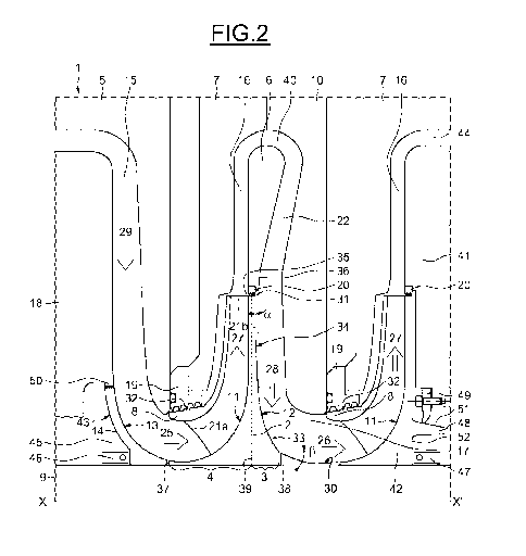
Figure 1 shows a portion 1 of a centrifugal compressor according to the
invention.
The compressor comprises a shaft 9 rotating around an axis X-X'. An impeller
wheel 2 is assembled around the shaft 9, so as to rotate around the axis X-X'
together with the shaft 9, and so as to transmit to the shaft axial forces
imparted by
fluids to the impeller 2. In the description "fluid" or "fluids" refers to the
fluids
processed by the radial rotating machine.
In the description, by "radial surface" one means a surface generated by a
series of
radial lines, i.e. a surface perpendicular to the axis X-X' of the rotating
machine 1.
By "axial surface", one means a surface generated by a series of axial lines,
i.e. a
portion of cylindrical surface with an axis parallel to the axis X-X'.
The impeller wheel 2 comprises a bladed hub portion 4 and a deflector portion
3,
placed downstream of the bladed hub portion 4.
By downstream one means downstream along the fluid flow path of the fluids
circulating within the rotating machine 1. Both bladed hub portion 4 and
deflector
portion 3 are in contact with the fluid flow and they contribute to guiding
the fluid
flow.
The bladed hub portion comprises a first radially outward facing surface 11
onto
which several impeller blades (not visible on the figures) are assembled,
distributed
between an inner line 21a and an outer line 2 lb.
The bladed hub portion is covered, on its radially external side, by a shroud
8. This
way, a fluid channel is defined between the blade hub portion and the shroud.
The
fluid channel is so designed as to deflect an incoming axial fluid flow 25
into an
outgoing radial centrifugal flow 27.
11
CA 02895570 2015-06-18
WO 2014/102125
PCT/EP2013/077259
The deflector portion 3 is placed downstream from the bladed hub portion 4,
and
comprises a second radially outward facing surface 12. Both the first outward
facing surface 11 and the second outward facing surface 12 extend at least
partially
in a radial direction and at least partially in an axial direction. The first
outward
facing surface 11 and the second outward facing surface 12 face opposite axial
directions. On the embodiment illustrated on figure 1, the impeller wheel
comprises
a first radial surface 37 at an axial end of first outward facing surface 11,
and a
second radial surface 38 at an axial end of second outward facing surface 12.
The impeller wheel extends axially between the first radial surface 37 and the
second radial surface 38. In some embodiments, surface 37 and/or surface 38
can
be reduced each to a circle line.
The bladed hub portion 4 and the deflection portion 3 can be defines by two
separate parts. They can, in an advantageous embodiment, be defined by a same
single part. In this case, an arbitrary axial limit between the two portions
can be
defined by any radial plane 39, the radial plane 39 running between the first
outward facing surface 11 and the second outward facing surface 12 without
intercepting any of the two surfaces. Such a radial geometrical plane 39 may
be
defined also in cases when the first outward facing surface and the second
outward
facing surface belong to two different parts.
In some embodiments, the first and the second outward facing surface can be
globally obtained by rotating around the axis X-X', some section lines of the
impeller wheel, such as the lines defining the contour of impeller wheel 2 on
figure
1 or on figure 2.
In other embodiments, the first and the second outward facing surface may not
be
exactly surfaces of revolution. They may for instance be obtained by a
periodical
rotation around axis )0c, of a set of initial generating surface portions.
The impeller wheel 2, the shaft 9 and the shroud 8 are surrounded by stator
parts
such as an inlet cover 5, a diffuser wall 7, a diaphragm 6 and a return
channel wall
10. The inlet cover 5 contributes to guiding the incoming axial fluid flow 25.
The
12
CA 02895570 2015-06-18
WO 2014/102125
PCT/EP2013/077259
incoming axial fluid flow 25 reaches an impeller eye defined by a radial
aperture
between the shroud 8 and the impeller 2. In some embodiments, such as on
figure
2, the inlet cover 5, may, together with a statoric upstream inlet wall 18,
define at
least partly an inlet channel 15 guiding a centripetal flow 29 towards the
impeller
eye, and deflecting the fluid flow into an axial flow before it enters the
impeller
eye.
Coming back to figure 1, the radial centrifugal flow 27 leaves the impeller 2,
then
is guided by a diffuser channel 16 defined between the diffuser wall 7 and a
diaphragm part 6. It then reaches a channel bend 40. The channel bend 40 is
defined between a portion of the diffuser wall 7, a portion of a return
channel wall
10, and the diaphragm part 6. It could also be defined only between a return
channel wall, and a diaphragm part. After the bend 40, the fluids are guided
through a return channel 17, following a centripetal flow direction, towards a
second deflecting surface 12 located at the back (i.e. on the downstream side)
of the
impeller wheel 2. An upstream portion of return channel 17 is defined in an
axial
space between diaphragm part 6 and return channel wall 10. The diaphragm part
6
may be held by return channel blades 22 bridging the axial gap between the
diaphragm part 6 and the return channel wall part 10. A downstream portion of
return channel 17 is defined between the return channel wall part 10 and the
second
outward facing surface 12. This downstream portion of the return channel is
curved
so as to deflect a centripetal fluid flow 28 into an axial fluid flow 26. The
axial
fluid flow 26 may then enter a second impeller eye of a second impeller 42
placed
downstream of the first impeller 2, as described on figure 2. Impeller 2 and
impeller 42 belong to a same multistage machine, for instance a two stage
machine
as in the embodiment depicted on figure 2. The multistage machine may comprise
more than two stages, in which case all impeller wheels of the machine, except
the
most downstream impellers, may comprise both a first outward facing surface
and
a second outward facing surface in the return channel associated with the
wheel, as
described previously. In some embodiments, the most downstream impeller wheel
may comprise no downstream deflecting surface, i.e. no second outward facing
surface. In other embodiments, the most downstream impeller wheel may have the
13
CA 02895570 2015-06-18
WO 2014/102125
PCT/EP2013/077259
same shape as the upstream impellers, the second outward facing surface being
simply not inserted into the fluid flow path of the rotating machine.
Coming back to figure 1, an impeller eye seal 19 is assembled to the diffuser
wall
7. The seal 19 contacts the shroud 8 so as to avoid leakage of the incoming
fluid
flow 25, and avoid it leaking directly towards the diffuser channel 16 without
traversing the fluid channel defined between the shroud 8 and the bladed hub
portion 4.
The second outward facing surface 12 comprises a deflecting surface of
sufficient
radial and axial extent, and of adequate curvature, in order to transform the
radial
centripetal flow 28 within the deflector portion 3 into an axial flow 26
leaving the
return channel 17.
In this way, the total dynamic axial forces exerted by the fluids onto the
second
outward facing surface 12 are opposite in direction and in amplitude to the
total
dynamic axial forces exerted by the fluids onto the first outward facing
surface 11.
The rotating machine may be a single stage machine, or a multistage machine.
To deflect an axial fluid flow into a radial fluid flow, the first outward
facing
surface 11 may be completed by a deflector surface portion 24 belonging to the
shaft 9, as on figure 1, or the first outward facing surface 11 may be
completed by a
deflector surface portion belonging to a ring assembled to the shaft (not
illustrated
on the figures), or the first outward facing surface 11 may be completed by a
deflector surface portion belonging to another deflector part 14 assembled
upstream
of the wheel 2, as illustrated on figure 2. In this case, the first outward
facing
surface 11 may be adjacent to a radial surface 37 defining axially the
upstream
limit of impeller wheel 2.
The second outward facing surface 12 extends radially far enough from the axis
X-
X' of the rotating machine. The second outward facing surface 12 extends
preferably radially further than the internal radius of the shroud 8 ¨internal
radius
being counted as a minimum distance between the axis X-X' and an inner face of
14
CA 02895570 2015-06-18
WO 2014/102125
PCT/EP2013/077259
the shroud 8 -. In a preferred embodiment, the difference between the maximum
diameter of at least a second outward facing surface 12 and the minimal
diameter
of the first outward facing surface 11 following it, is more than 150% of the
radial
distance between the inner diameter of the shroud covering the first outward
facing
surface and the minimal diameter of the first outward facing surface 11.
In this way, sufficient axial deflection forces are provided by the fluids in
return
channel 17, and the downstream side of the impeller wheel 2 is subjected to
sufficient axial deflecting forces, in order to balance the deflecting forces
exerted
on the upstream side of the impeller wheel.
Preferably, the second outward facing surface 12 comprises a radially outer
surface
portion 34 which comprises a radial surface portion, or comprises a radially
outer
surface portion which comes tangent to a geometrical radial plane.
In some embodiments, the second outward facing surface 12 may not come exactly
tangent to a radial plane, but it comprises a circumferential, radially outer
surface
portion 34, that makes a limit angle a of no more than 100, and preferably no
more
than 5 , from a radial plane. The limit angle a may for instance be measured
as the
angle between the axial direction and a direction normal to the second outward
facing surface 12. On both figures 1 and 2, the amplitude of limit angle a is
exaggerated, as the corresponding surface angle is very close to zero.
As can be read from figure 2, one could imagine a deflection of the fluid flow
between the radial centrifugal direction of the fluid flow 27 leaving the
upstream
side of impeller wheel 2, and the centripetal fluid flow in the upstream part
of
return channel 17, which could reach a deflection angle of more than 180
with.
Still, in a preferred embodiment, this deflection angle is no more than 180 ,
in
order to improve the balancing effect of dynamic axial forces. To the same
purpose,
the whole second outward facing surface is curved axially forwards, that is to
say,
when one moves radially along this surface towards axis )0c, the axial
coordinate
of a contact point with the surface can only increase (in the downstream
direction)
or stay constant for a while, never decrease.
CA 02895570 2015-06-18
WO 2014/102125
PCT/EP2013/077259
As a consequence, all portions of surface 12 are radially outward facing. By
avoiding surface portions facing radially inwards, one gets a better balancing
effect
of fluid forces exerted on impeller wheel 2.
To deflect a radial fluid flow into an axial fluid flow, the second outward
facing
surface 12 may be completed by a deflector surface portion 30 belonging to the
shaft 9, as illustrated on figure 2, or belonging to a ring 23 assembled to
the shaft,
as illustrated on figure 1, or belonging to a downstream impeller wheel (not
illustrated). In this case, the second outward facing surface 12 may be
adjacent to a
radial surface 38 defining axially the downstream limit of impeller wheel 2.
Preferably, the second outward facing surface 12 comprises a central surface
portion 33 which comprises an axial surface portion, or comprises a central
surface
portion 33 which comes tangent to an axial cylinder surface.
In some embodiments, the second outward facing surface 12 may not come exactly
tangent to an axial cylinder surface, but the second outward facing surface 12
should comprise a central surface portion 33 that makes an angle 0 of no more
than
100, and preferably no more than 5 , from an axial direction, for the same
reasons
aiming at achieving an efficient axial balance of dynamic forces exerted by
the
fluid. The angle 0 may be measured between a tangent line to the surface
comprised in a radial plane, and the axial direction of axis XX'.
As can be seen on figure 1, the rotating machine 1 may comprise a downstream
pressure seal 20, which can be for instance a labyrinth seal, and which is
placed
between the diaphragm part 6 and a first seal portion 31 of the impeller wheel
2.
The seal portion 31 may be a stepped, or preferably an unstepped, surface,
running
circumferentially around the wheel 2.
In the embodiment illustrated on figure 1, the first seal portion is placed
radially
closer to the axis XX' than the outer edge of the impeller wheel. The first
seal
portion 31 is separated from the outer edge by a more or less radial surface
portion,
and is separated from the shaft 9 by the second outward facing surface 12.
16
CA 02895570 2015-06-18
WO 2014/102125
PCT/EP2013/077259
The rotating machine 1 may comprise a second seal surface portion 32 running
around the shroud 8 and facing the seal 19 of the impeller eye. This second
seal
surface portion 32 is preferably a stepped surface. The distance of this
surface from
axis XX' may for instance be measured as the average value between the axial
surface portion which is in contact with seal 19, and is closest to axis XX',
and the
axial surface portion which is in contact with seal 19, and is placed at the
largest
distance from axis XX'.
In the embodiment depicted on figure 1, the radial distance from axis XX', of
the
first seal portion 31, is almost the same - that is here, differing of no more
than
20%, and preferably of no more than 10% - as the average distance separating
the
second seal surface portion 32. An advantage of this embodiment is that the
static
pressure differences are better balanced than in the embodiment depicted on
figure
2.
In the embodiment, illustrated on figure 2, the first seal portion runs along
a
radially outer edge 35 of impeller wheel 2, which reduces the overall length
of the
machine.
First and second seal portions 31 and 32 may be flat axial surfaces, stepped
axial
surfaces, or teethed surfaces facing a flat or a stepped surface on seals 19
or 20.
The second outward facing surface 12 is placed so as to come flush - according
to
embodiments, sometimes with seal 20 in between - with the diaphragm wall 36
defining the return channel.
The second outward facing surface 12 together with the diaphragm wall 36, form
an almost continuous surface designed to guide the fluid first in a
centripetal
direction 28, then to deviate it to an axial direction 26. The second outward
facing
surface 12 together with the diaphragm wall 36, sometimes with a portion of
more
or less radial surface belonging to seal 20, form a deflecting surface, the
radial
section line of which has a continuously varying radius of curvature. Wall 36
may
be mainly radial, or may be slightly frustoconical getting wider towards the
shaft 9.
17
CA 02895570 2015-06-18
WO 2014/102125
PCT/EP2013/077259
As was already hinted above, figure 2 illustrates another embodiment of a
radial
rotating machine according to the invention.
Similar elements to figure 1 can be found on figure 2, which are designated by
same references.
On the embodiment of figure 2, the radial rotating machine is a multistage
machine, in the illustrated case a two stage machine. It comprises a first
impeller
wheel 2 with a first outward facing surface and a second outward facing
surface as
described previously. It also comprises a downstream impeller wheel 42 with
only
a first outward facing surface 11. The dynamic axial forces exerted on first
outward
facing surface 11 of wheel 2 are compensated by dynamic axial forces exerted
on
second outward facing surface 12 of wheel 2. The second, and last, impeller
wheel
42 is not followed by a return channel, as the diffuser 16 is followed by an
outlet
channel 44 defined between diffuser wall 7 and a final diffuser wall 41. The
dynamic axial forces exerted on first outward facing surface 11 of wheel 42
are
compensated by dynamic axial forces exerted on a third outward looking surface
13
belonging to an upstream deflector part 14, placed upstream of the first
impeller
wheel 2. The third outward looking surface 13 has a shape similar to the shape
of
the second outward facing surface, and is placed flush with a radial wall
surface
portion belonging to an upstream inlet wall part 18. A seal, for instance a
labyrinth
seal, may be present between the inlet wall part 18 and a radially outer edge
of
deflector part 14. In other embodiments, a gap may be present between the
inlet
wall part 18 and a radially outer edge of deflector part 14.
In a preferred embodiment, deflector part 14 comprises a radially inward
facing
surface 43 defining a free space 45 between the upstream deflector part 14 and
the
shaft, opened around the shaft at the upstream end of the deflector part. In
this way
the total weight of the rotor is reduced. In the embodiment illustrated on
figure 2,
the radial rotating machine comprises an upstream balance drum seal 50 placed
so
as to avoid gas leakage between the inlet channel 15 and the hollow space 45.
The
radial rotating machine of figure 2 comprises a downstream balance drum seal
49,
assembled to the final diffuser wall 41 so as to come into contact with an
axially
18
CA 02895570 2015-06-18
WO 2014/102125
PCT/EP2013/077259
extending surface 51 belonging to an axial protrusion 48 of the most
downstream
bladed hub portion 42.
The protrusion 48 is a more or less an annular axially extending protrusion,
extending axially to the downstream side of the bladed hub portion 42, so as
to
define an axially extending surface 51 radially close to the diffuser wall 7.
Seal 49 makes it possible to get a different gas pressure within the gas
channel
along the most downstream impeller 42, from the pressure on an at least partly
radial surface of the impeller part, surrounded by protrusion 48. This
pressure
difference generates axial forces which can be tuned to compensate for at
least part
of the static axial load exerted on the impellers and deflectors assembled to
the
shaft 9. A similar tuning effect is also achieved with seal 50.
In the illustrated embodiment, the deflector part 14 comprises a radial
surface
portion within the hollow region 45, facing a half axial thrust bearing 46,
for
example a magnetical half bearing. In other embodiments, deflector part 14 may
also comprise a radial surface portion without defining hollow region 45, and
the
radial surface portion may face a half axial thrust bearing. When the half
bearing is
placed in a hollow region 45, the overall length of the machine is reduced. A
second half axial bearing 47, such as a magnetical half bearing, may face a
downstream radial surface belonging to a downstream impeller wheel. Thanks to
the self balancing of dynamical axial forces due to the outward facing
surfaces, the
machine may comprise only 2 half magnetical bearings 46 and 47, without a need
for additional thrust bearings.
A rotating machine according to the invention, with some features either of
figure 1
or of figure 2, could have more than 2 stages, for example a number n of
stages, n
being greater than, or equal to two. It could comprise, from the upstream side
to the
downstream side along axis )0c, an upstream deflector part 14, a number n-1 of
impeller wheels 2 with a first and a second outward facing surface, and a
downstream wheel either without a second outward facing surface S, or with a
second outward facing surface not pertaining to a return channel.
19
CA 02895570 2015-06-18
WO 2014/102125
PCT/EP2013/077259
A rotating machine according to the invention, especially a single stage
machine,
could be devoid of a second outward looking surface downstream of any impeller
wheel, and comprise only a first outward looking surface 11 on an impeller
wheel,
associated with an upstream "third" outward looking surface 13, configured to
balance the axial forces exerted by the fluid on the first outward looking
surface 11.
The invention is not limited to the embodiments described and illustrated
above,
which are to be regarded as mere examples of a wider range of embodiments.
The first and second, the first and third outward looking surface may or may
not
belong to a same part. The balancing effect may not be calculated to be
achieved on
two adjacent surfaces, but may be calculated to be achieved between all
axially
upstream and all axially downstream deflecting rotating surfaces.
When the first and second outward looking surface belong to a same part that
is the
impeller wheel 2, one can say that a portion of the return channel 17 is
delimited by
the impeller wheel 2. In some embodiments, such as on figure 2, the statoric
return
channel blades 22 extend at least partially in a portion of the return channel
delimited by the second outward facing surface 12.
The rotating machine preferably handles gases but may handle other types of
fluids, such as gaseous liquid droplets suspensions.
A portion of the second outward facing surface 12 may belong to a same part
defining also the upstream side of impeller wheel 2, and another portion of
the
second outward facing surface 12, or several other portions, may belong to
either
the shaft itself, or may be defined by separate parts assembled to the shaft.
With an impeller wheel assembly according to the invention, the remainder of
axial
forces which is to be counterbalanced by axial thrust bearings is reduced. The
size
of the axial thrust bearing may then be reduced, or oil bearings can be
replaced by
magnetical thrust bearings. In the embodiment of figure 2, the total length of
the
radial rotating machine may be shorter than in prior art machines, due to the
fact
CA 02895570 2015-06-18
WO 2014/102125
PCT/EP2013/077259
that the axial distance between the impeller wheel channel and the return
channel is
reduced to a minimum.
In the embodiment of figure 1, the total axial length of the machine is
higher, but
static pressure forces are self-balanced in addition to the self-balancing of
dynamical pressure forces.
Owing to the axial forces self balancing ability of the impeller wheel
assembly,
higher fluid throughputs can be allowed through the rotating machine. Such
high
throughputs sometimes occur in transient regimes, which formally implied
designing much bulkier thrust bearings.
The impeller wheel assembly according to the invention does enable to
construct
more compact radial rotating machines with wider functioning ranges,
especially as
fluid throughput is concerned.
21