Note : Les descriptions sont présentées dans la langue officielle dans laquelle elles ont été soumises.
CA 02895878 2015-06-12
UNITED ST!' TES PATENT APPLICATION
FOR
SYSTEM AND METHOD FOR IMAGING SUBSURFACE OF SPECIMEN
INVENTOR:
MANISH KULKARNI
Prepared by:
Geeta Kadambi
Riddhi IP LLC
43526 Gallegos Avenue,
Fremont, California 94539
Phone: 510-205-9549
RIPLLC006.001CIP1
CZOSS REFERENCE TO RELATED APPLICATIONS
[0001] The instant application is a continuation-in-part application and
claims priority to pending US patent
applications 12/732484, filed on 26th March, 2010 and US Patent Application
12/706717, filed on 17th
February 2010. The disclosure is hereby incorporated by this reference in its
entirety for all of its teachings.
The PCT application claims priority to pending US patent application number
13/723006 filed on Dec 20,
2012.
FIELD OF TECHNOLOGY
[0002] The following description relates to a system, method and an apparatus
for imaging and evaluating
the microstructure of any specimen on the subsurface. More specifically the
description is relevant to
imaging of biological specimen such as a retina in diabetic patients using
optical coherence domain
reflectometry (OCDR), optical frequency domain reflectometry (OFDR), optical
coherence tomography
(OCT), Doppler processing and Doppler OCT technology in combination.
BACKGROUND
[0003] Optical Coherence Domain Reflectometry (OCDR) has been playing a major
role in industrial,
scientific metrology and medical diagnostics. Optical Coherence Tomography
(OCT) is a 2-D extension of
OCDR and provides micron-resolution cross-sectional images of specimens. Most
of the industrial and
clinical OCDR, OFDR and OCT machines are disparate, expensive, cumbersome to
use, bulky, not very
CA 02895878 2015-06-12
efficient and are fragile. Everett et al. (2006) discusses these systems in
isolation and in some combinations
in detail.
[0004] However, a more compact and integrated system and an apparatus would
make diagnosis more
accurate and the apparatus more portable.
SUMMARY
[0005] The invention discloses a system, method and apparatus, for evaluating
the retinal microstructure in
diabetic patients and other substructure for failure analysis using optical
coherence domain reflectometry
(OCDR), optical frequency domain reflectometry (OFDR), optical coherence
tomography (OCT), Doppler
processing and Doppler OCT technology in combination.
[0006] In one embodiment, an apparatus comprises of a light source, isolator,
beam splitter, optical delivery
unit, specimen, volume-phase holographic grating unit, detector array and a
processor containing novel
algorithms for image processing. This is described as the basic configuration
throughout the instant
application with minor addition and deletion of components. In another
embodiment, the apparatus
mentioned above has also at least one of a faraday rotator mirror, fractional
wave mirror, waveplate (e.g.,
X/8), a fiber-optic mirror and a free space mirror.
[0007] In another embodiment as an additional feature, a polarization
compensator is added to the basic
configuration mentioned above. In one embodiment, a fiber stretcher is added
in the basic configuration.
The fiber stretcher is used to adjust the path-length in the corresponding arm
of the system.
[0008] In one embodiment, a system comprising of light source, provides a
broad band light for acquiring
ar, image from subsurface area of a specimen. The specimen may be, but not
limited to a moving sample, a
stationary sample or a combination of both. In another embodiment, the system
is modular so that a user
can add off-the-shelf products to enhance the system capabilities. In another
embodiment, several
combinations of the basic configuration and additional components may be added
to enhance the
performance of the apparatus as a system as shown in the various figures that
accompany this application,
but not limited to only those.
[0009] In another embodiment, a compensating algorithm resides in the
processor to create a superior
image. The processor uses the algorithms such as the frequency resampling,
demodulation, dispersion
compensation, and Doppler processing to produce highly sensitive and high
quality images. In another
embodiment, the system performs spectroscopic detection. The resultant spectra
are analyzed by the
processor using inverse Fourier transformation and relevant signal processing
for obtaining depth
dependent (i.e. axial) reflectivity profile called A-scan. In another
embodiment, two dimensional
temographic images, B-scan, are created from a sequence of axial reflectance
profiles acquired by scanning
the specimen.
2
CA 02895878 2015-06-12
[0010] In one embodiment, a system may comprise of a light source, isolator,
processor, fiber stretcher,
source arm, reference arm, sample arm, detection arm, beam splitter, detector
array, volume-phase
holographic grating unit, optical delivery un , X18 waveplate, fractional wave
mirror and a specimen for
ar'alysis.
[0011] In another embodiment, the system comprises of a light source,
isolator, processor, detector array,
fiber stretcher, source arm, reference arm, sample arm, detection arm, beam
splitter, volume-phase
holographic grating unit, optical delivery unit, polarization compensator,
mirror and a specimen for
analysis.
[0012] In another embodiment, the system comprises of a light source,
isolator, processor, detector array,
fiber stretcher, source arm, reference arm, sample arm, detection arm, beam
splitter, volume-phase
holographic grating unit, optical delivery unit, polarization compensator and
another optical delivery
system located on the reference arm, free space mirror and a specimen for
analysis.
[0013] In another embodiment, a system may comprise of a tunable light source,
isolator, processor, fiber
stretcher, source arm, reference arm, sample arm, detection arm, beam
splitter, detector, optical delivery
unit, V8 waveplate, fractional wave mirror and a specimen for analysis.
[0014] In another embodiment, the system comprises of a light source,
isolator, processor, detector array,
fiber stretcher, source arm, reference arm, sample arm, detection arm, beam
splitter, volume-phase
holographic grating unit, optical delivery unit, polarization compensator
located on the sample arm,
fractional wave mirror and a specimen for analysis.
[0015] In one embodiment, a system may comprise of a light source, isolator,
processor, fiber stretcher,
scurce arm, reference arm, sample arm, detection arm, beam splitter, detector
array, volume-phase
h9lographic grating unit, optical delivery unit, X/8 waveplate, faraday
rotator mirror and a specimen for
analysis.
[0016] In one embodiment, a system may comprise of a tunable light source,
isolator, processor, fiber
stretcher, source arm, reference arm, sample arm, detection arm, beam
splitter, detector, optical delivery
unit, X/8 waveplate, faraday rotator mirror and a specimen for analysis.
[0017]In another embodiment, the system comprises of a light source, isolator,
processor, detector array,
fiber stretcher, source arm, reference arm, sample arm, detection arm, beam
splitter, volume-phase
holographic grating unit, optical delivery unit, polarization compensator
located on the sample arm, faraday
rotator mirror and a specimen for analysis.
[0018] In another embodiment, the system enables a user to adjust the
reference arm and the sample arm in
order to adjust the variance of the light beam to get a better quality image.
[6019] In one embodiment, a method of acquiring sensitive, high quality image
of the subsurface for
diagnostics and failure analysis is described.
3
CA 02895878 2015-06-12
[0020] In another embodiment, light from a broadband light source operating at
a suitable center
wavelength is sent to an isolator, and then to the beam splitter using the
source arm of the apparatus. In
ariother embodiment, the beam splitter splits the broadband light into two
parts. One part of the light beam
goes to the reference mirror using the fiber s etcher (on the reference arm)
and other beam goes to the
specimen using the sample arm.
[0021] In another embodiment, the reflected light from the mirror using the
reference arm joins the light
reflected from the specimen using the sample arm. In another embodiment, the
combined light from the
reference arm and sample arm is split again at the beam splitter and part of
the beam goes back to isolator.
The other part of the beam goes to the VPH (volume-phase-holographic grating
unit) and detector array
using the detector arm. The beam then is transformed using novel algorithms
that are discussed in detailed
description and transformed to produce high quality, sensitive images. In
another embodiment, if the image
quality is poor then the whole process is repeated, the user is given the
option to adjust the reference arm
length, adjust the polarization using polarization compensation, or focus the
light using optical delivery unit
to; further improve the image.
[0022] In one embodiment the apparatus comprising of many components and
systems is modular. In
another embodiment the processor/computer-readable media houses the novel
algorithm to process the
beam that has the spectrophotometric image information of the specimen.
[0023] In one embodiment, a method to process the acquired image using several
types of systems using
the algorithms residing in the computer-readable media is described.
[0024] The above mentioned summary presents a simplified version of one or
more embodiments in order
to, provide a basic understanding of such embodiments. This summary is not an
extensive overview of all
contemplated embodiments, and is intended to neither identify key or critical
elements of all embodiments
nor delineate the scope of any or all embodiments. Its sole purpose is to
present some concepts of one or
more embodiments in a simplified form as a prelude to the more detailed
description that is presented later.
Other aspects will be apparent from the following description, figures and the
appended claims.
BRIEF DESCRIPTION OF THE DRAWINGS
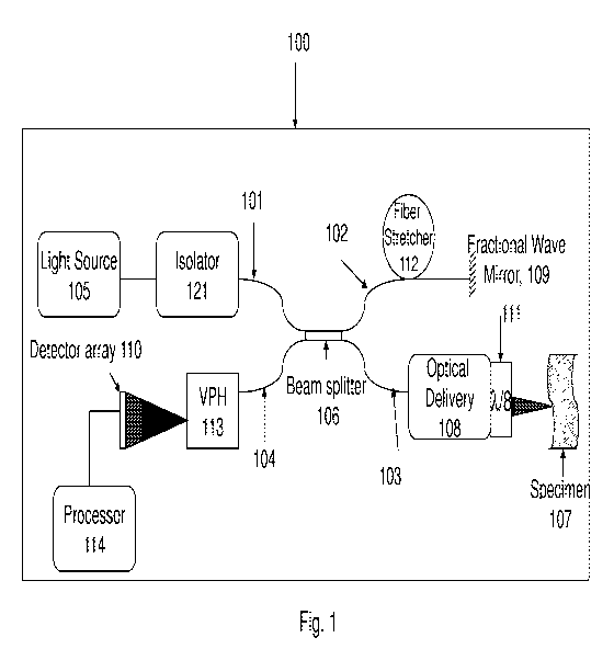
[0025] Fig. 1 is a block diagram of an OCDR-OCT system 100, in accordance with
an embodiment of the
present invention; the key novel elements being volume phase holographic
grating unit, fiber optic
Fractional Wave mirror, fiber stretcher, and X/8 waveplate.
[Q026] Fig. 2 is a block diagram of the OCDR-OCT system 100 similar to that in
Fig. 1 except that the
Fractional Wave mirror is replaced by a fiber optically integrated mirror, and
the X/8 waveplate is
eliminated and a polarization compensator is introduced.
4
CA 02895878 2015-06-12
[0027] Fig. 3 is a block diagram of the OCDR-OCT system 100 similar to that in
Fig. 2 except that the fiber
optically integrated mirror is replaced by a free space mirror.
[0028] Fig. 4 is a block diagram of the OFDR-OCT system 415 similar to that in
Fig. 1 except that the
broad-band source is replaced by a tunable frequency source, detector array is
replaced by a single high-
speed detector, and the diffraction grating is oliminated. Such a system is
called swept-source OFDR/OCT.
[0029] Fig. 5 is a block diagram of the OCDR-OCT system 100 similar to that in
Fig. 1 except the X/8
waveplate is eliminated and a polarization compensator is introduced in the
sample arm.
[0030] Fig. 6 is a block diagram of the OCDR-OCT system 100 similar to that in
Fig. 1 except that the
Fractional Wave mirror is replaced by a fiber optically integrated Faraday
Rotator Mirror.
[0i031] Fig. 7 is a block diagram of the OFDR-OCT system 415 similar to that
in Fig. 4 except that the
Fractional Wave mirror is replaced by a fiber optically integrated Faraday
Rotator Mirror.
[0032] Fig. 8 is a block diagram of the OCDR-OCT system 100 similar to that in
Fig. 5 except that the
Fractional Wave mirror is replaced by a fiber optically integrated Faraday
Rotator Mirror.
[0033] Fig. 9 is a flow chart of describes a method of acquiring an image from
a specimen using the
OCDR-OCT system.
[0034] Fig 10 is a flow chart of method of using the apparatus.
[0035] Fig 11 is a flow chart of overview of methods of the signals and images
being processed from the
start to finish.
[0036] Fig 12 is a flow chart of method of demodulating the signal to recover
the complex envelope of the
OCT/OCDR/OFDR signal.
[0037]Fig. 13 is a flow chart of method of Doppler processing the signal to
estimate the Doppler shift and
the corresponding velocities of the particles in the specimen..
[0038] Other features of the present embodi:-lents will be apparent from the
accompanying figures and
frpm the detailed description that follows.
DETAILED DESCRIPTION
[0039] The instant disclosure describes a technological advancement of
acquiring an image that is
stationary, moving and/or combination of stationary and moving specimen in
subsurface area and
enhancing the quality of the image by using proprietary algorithms. The
disclosure also describes an
apparatus, a system and a method for evaluating the retinal microstructure in
diabetic patients and other
substructure for failure analysis using optical coherence domain reflectometry
(OCDR), optical frequency
domain reflectometry (OFDR), optical coherence tomography (OCT), Doppler
processing and Doppler
OCT technology in combination.
CA 02895878 2015-06-12
[0040] OCDR-OCT System: Fig. 1 shows an OCDR-OCT system 100 comprising of a
light source 105,
isolator 121, processor 114, fiber stretcher 112, source arm 101, reference
arm 102, sample arm 103,
detection arm 104, beam splitter 106, detector array 110, volume-phase
holographic grating unit 113,
optical delivery unit 108, A/8 plate 111, Fractional wave mirror 109 and a
specimen 107for analysis. This is
one of the preferred embodiments for our invention.
[0041] A light source 105, in a system or as d part of the apparatus, may
comprise of off-the-shelf light
sources.
[0042] The center wavelength (A0) most ideal for the retinal applications
range from 750nm till 1050nm.
Water (and aqueous humor) absorption is minimal for this wavelength range. The
power for retinal
applications ranges from 0.1mW to 10mW. Per ANSI safety standards only 0.75mW
are permitted incident
on the eye at this wavelength range of 750nm till 1050nm. The center
wavelength most ideal for the non-
retinal applications (e.g., skin, anterior segment of the eye,
gastrointestinal tract, lungs, teeth, blood vessels,
subsurface area of semi-conductors, chip manufacturing, sensitive medical
equipment's etc.) range from
1050nm till 1350nm.The longer wavelength is more suitable for thick scattering
tissues since scattering is
less at higher wavelengths. The system depth resolution (DR) is inversely
proportional to the FWHM
spectral width (or bandwidthAA). It is given by the following equation:
2/n2 202
DR = LIA (Eq 1)
[0043] The full-width-half-max (FWHM) spectral width of the light source
typically ranges from lOnm till
150nm. The power for non-retinal applications ranges from 0.1mW till 30mW in
the wavelength range
from 1050nm till 1350nm. The full-width-half-max (FWHM) spectral width of the
light source typically
ranges from lOnm till 150nm.
[0044]The light source 105 may be electrically operated. These can be battery
operated while in transit.
The forward voltage typically ranges from 2 to 10Volts. The forward current
typically ranges from 100mA
to 1A. Some of these sources need to be thermo-electrically controlled (TEC).
The operating internal
temperature for some sources is typically 25 C. The corresponding thermistor
resistance is 10kilo-Ohms
(10kS2). Typical TEC current is 1.5A. Typical TEC voltage is 3-4V. The light
source may also be tunable
light source as shown in other system/apparatus embodiments.
[0045] The isolator 121 protects the light source from back reflections and
permits the transmission of
light in the forward direction with a limited loss. The fiber-optic isolator
used in idevice would need to
operate on a broad range of spectrum to cover the full spectral-width of the
light source (Depending upon
the source spectral shape, typically 2* FWHM bandwidth AA). Thus the operating
wavelength range is
2to +/¨Al. Typical isolation is 20-40dB, and insertion loss is 0.5-3dB. The
polarization dependent loss is
typically 0.5dB or less. Return loss is typically more than 40dB.
6
CA 02895878 2015-06-12
[0046] The isolator 121 comprises of an input linear polarizer, a (A /8)
Faraday rotator or a waveplate, and
an output linear polarizer. The (A /8) Faraday rotator or a waveplate rotates
the light transmitted through
the input polarizer by 45 degrees. The output polarizer needs to have the same
direction as "the input
polarizing direction rotated by 45 degrees" in order to have the maximum
transmission and maximum
isolation. The light returning to the isolator from the remaining system gets
linearly polarized by the output
polarizer and is rotated by 45 degrees, making it orthogonally polarized as
compared to the input polarizing
direction. Thus, the returning light is totally 'absorbed.
[0047] Fiber stretcher 112 consists of a fiber looped around a piezoelectric
device (which is a solid block
that can be expanded or contracted by electric voltage). The purpose of a
fiber stretcher is to increase or
decrease the path-length in the interferometer that is on the detection arm by
increasing or decreasing the
filer-length. Although the fiber stretcher 112 is shown in the reference arm,
it can be placed ether in the
reference arm or sample arm. If the fiber stretcher 112 is kept in the
reference arm, since the fiber is looped
around the piezoelectric device, care must be taken to provide extra fiber in
the sample arm so that the
sample arm and reference arm path lengths are matched.
[0048] The fractional wave mirror 109 consists of a fiber-optic minor preceded
by a fractional [45 degrees
(X/8)] waveplate. The polarization of light incident on the wave plate is
rotated by 45 degrees, and is
directed to the mirror. The reflected light is further rotated by 45 degrees
by the fractional [45 degrees
(X/8)] waveplate and hence the resulting polarization is orthogonal to the
incident polarization. We would
use a fiber optically integrated birefringent reference mirror is at least one
of fractional wave mirror,
mirror, free space mirror and Faraday rotator mirror. A modified formula based
on LeFvre is disclosed in
this disclosure and which is as follows:
[0049] Mechanical stress on the fiber is causes birefringence in the fiber.
Stress can be generated by
simply bending the fiber. According to LeFevre (US 4615582), the fractional
wave plate can be built by
looping the fiber into N loops having a radius R. The refractive index
difference An for two orthogonal
polarizations is given by
An = b
(Eq 2)
b is a constant depending upon the photoelastic coefficient of the fiber, r is
the radius of the fiber and R
is the radius of the fiber loop. Thus, if we want to create a A /m (where m is
an integer) waveplate,
which will introduce a path-length shift of A /m between 2 polarizations,
we'll need to create a loop of
fiber length L to create the path-length shift of An.L. However, since the
length of the fiber is also equal
to 2n-NR, where N is the number of loops, we get
(27-(NR)b ()2 = (Eq 2)
R m
7
CA 02895878 2015-06-12
or
r2
R= (27mN)b (Eq 4)
To create a fractional wave plate of 11, and N = 1 (single loop), b = 0.25, m
= 8, r = 125 microns,
= 0.8 microns, we get
R = (27r8)0.25 (12s)2- = 57r * 15625 = 24.54cm (Eq 5)
0.8
Please note that a (2M + 1)A /m waveplate where M is an integer between -oo to
co will have a similar
effect as a A /m waveplate.
[0050] In typical state-of-the-art OCT systems, light exits a fiber tip in the
reference arm and the light
returns from a retro reflecting mirror mounted in air. This increases system
complexity and bulkiness. In
some embodiments of instantly described invention, a fiber-optically
integrated fractional wave mirror 109
in the reference arm 102 of the OCDR-OCT system 100 can be used. Since the
polarization of the retro
reflected light is orthogonal to the incident light, fiber birefringence
effects effectively get cancelled in the
reference arm 102.
[0051] Detector array 110 is a line-scan camera. It has typically 1024-4096
pixels, though the proposed
embodiment is not limited to these numbers. Typically it is a CCD or CMOS
camera. Line-rate (rate of
acquisition of arrays) is typically 10000 lines/s to 400000 lines/s, though
the proposed embodiment is not
limited to these numbers. Each pixel outputs a value which typically has an 8-
bit or 12-bit format, though
the proposed embodiment is not limited to these numbers. The pixel size is
typically 14 microns (height)
and 14 microns (width). The light dispersed by the grating is focused on the
detector array. The output of
the array (line-scan camera) is typically directed to the computer using an
Ethernet cable (e.g., Gigabit
Ethernet) or a USB (typically 2.0 or 3.0) cable, etc. The operating wavelength
ranges from 400nm to
ll 00nm for retinal applications. The above numbers and examples are given for
illustrative purposes only,
the proposed embodiment is not limited to these numbers or examples.
[0052] The beam splitter 106 (made of fiber optics) splits the light typically
into 50/50. It is built using two
fused single-mode fibers. The fiber for retinal applications (-800nm
wavelength) has 4-6 microns core
diameter and 125 microns cladding diameter, 0.130 core numerical aperture
(NA), cutoff wavelength of
typically 730nm. The insertion loss (in addition to designed 3dB or 50% loss)
is typically 0.3dB. For the
cQuplers used for OCT, the length of the fiber in the reference and sample
arms is very important and the
lengths are specified with tight tolerances.
[0053] The waves reflected back from the sample arm 103 and the reference arm
102 interferes at the
dQtector array 110. Since the interference signal is only created when the
polarization in the reference arm
102 matches with that in the sample arm 103, in some embodiments, one can
include by way of example
8
CA 02895878 2015-06-12
but not by limitation a 45 degrees X/8 waveplate 111 in the sample arm 103
just before the light is incident
on the optical delivery unit 108. Since the polarization of the retro
reflected light will be almost orthogonal
to the incident light (considering the fact that the birefringence in the
specimen 107 will modify the
polarization state), the birefringence effects in the sample arm fiber 103 of
the interferometer 100 will get
cancelled. In a preferred embodiment, the X/8 waveplate 111 is constructed
using fiber optic components.
[0054] In an embodiment of this invention, other waveplates (non-45 degrees
Faraday rotators) can be
tied. The quality of the interferometric signal (e.g., contrast and signal to
noise ratio) will be better or
worse depending upon the polarization properties of the specimen in the sample
arm.
[0055] The instant system and apparatus that comprises of Optical coherence
tomography (OCT) and
6.7..DR that is very similar to ultrasound imaging. OCDR-OCT provides cross-
sectional images of micro-
features that are acquired from adjacent depth resolved reflectivity profiles
of the tissue. OCT also employs
a fiber optically integrated Michelson interferometer illuminated with a short
coherence length light source
such as a superluminiscent diode (SLD). The interferometric data are processed
in a processor/computer
and displayed as a gray scale image. In an OCDR-OCT image, the detectable
intensities of the light
reflected from human tissues range from 10-5 to 10-11th part of the incident
power.
[0056] OCDR-OCT system 100 and OFDR-OCT 415 are able to image sub-surface
retinal microstructure
and has been useful for diagnosis and management of diabetic retinopathy.
Abnormalities in blood-flow
ci-culation due to diabetes are the root cause behind retinal microstructure
damage. However, no clinical
tools exist that can perform functional and velocity mapping of blood vessels
in the retina for tracking early
development of diabetic eye diseases. Therefore, there is a need for an
automated, low-cost and compact
tool based on Doppler OCT for tracking progression and management of diabetic
retinal diseases by
performing 3-D functional mapping of blood circulation in the retina. Such a
device will be extremely
useful in detecting earliest signs of diabetic retinopathy and hence it will
be an ideal tool for screening
diabetic patients at risk of developing retinopathy. Since it has been proven
that glucose and blood-pressure
control are the best methods for managing diabetic retinopathy, instant
Doppler OCT system will be an
ideal low-cost tool, which will permit screening as well as management for the
disease. The invention
pitesented here provides such a system and addresses these issues.
[q057]In another preferred embodiment, the X/8 waveplate 111 is a fractional-
waveplate constructed using
fiber optic components. It would be constructed in the optical delivery unit
near the end of the fiber
sqgment in the optical delivery unit.Fractional waveplate 111 is located on
the sample arm of the apparatus.
It may be made an integral part of the optical delivery 108. The fractional
wave mirror 109 consists of a
fiper-optic minor preceded by a fractional [45 degrees (A /8)] waveplate. The
polarization of light incident
of the waveplate is rotated by 45 degrees, and is directed to the mirror. The
reflected light is further
rotated by 45 degrees by the fractional [45 degrees (A /8)] waveplate and
hence the resulting polarization is
9
CA 02895878 2015-06-12
orthogonal to the incident polarization. In another embodiment, a free-space-
bulk 45 degrees (A /8) wave
plate is used at the end of the optical delivery unit.
[0058] Instant OCDR- OCT system uses spectroscopic detection method. Basically
the interferometric light
exiting the detector arm 103 is dispersed via a grating. The spectra are
acquired using a line-scan camera.
The resulting spectra are typically (by way of example, not by limitation)
transferred to a processor for
inverse Fourier transforming and relevant signal processing (such as obtaining
the complex envelope of the
interferometric signal) for obtaining depth dependent (i.e., axial)
reflectivity profiles (A-scans). The axial
resolution is governed by the source coherence length, typically ¨3-10 pm. Two
dimensional tomographic
images (B-scans) are created from a sequence of axial reflectance profiles
acquired while scanning the
pobe beam laterally across the specimen or biological tissue.
[0059] A-scan: A-scan is a plot of reflectivity of scatterers and layers as a
function of depth at a given
lateral location. It is computed as follows:
a),The interferometric light exiting the detector arm is dispersed via a
grating.
b) The dispersed light is a spectrum which is focused on a detector array or a
line-scan camera.
c) The recorded spectra are typically transferred to a processor
d) An inverse Fourier transform of the spectrum is computed
e) Relevant signal processing is performed (such as removing the duplicate
data and strong spikes at the
center of the inverse Fourier transform)
f) The resulting arrays is a depth dependent (i.e., axial) reflectivity
profiles (A-scans).
g)'The axial resolution is governed by the source coherence length, typically
¨3-10 jam.
[0060] B-scan: Two dimensional tomographic images (B-scans) are created from a
sequence of axial
reflectance profiles acquired while scanning the probe beam laterally across
the specimen or biological
tissue. The following are detail steps:
a) An A-scan is acquired at a given lateral location.
b) A mirror is scanned using a scanner such as a galvanometer in the optical
delivery unit
c) Multiple A-scans are acquired at various lateral locations.
d) A matrix is generated where columns indicate different lateral locations
and rows indicate
reflectivity at each depth in each A-scan
e) The matrix is displayed as an image, which is also a B-scan
[0061] Processor comprises of many algorithms that are discussed below. There
may be a combination of
algorithms that may be used for image formation. The algorithms may be used
individually or in certain
CA 02895878 2015-06-12
sets, or in a serial manner. Figs 11, 12 and 13 discuss some embodiments, but
the use is not limited to that
only.
[0062] Dispersion compensation is an algorithm used in the instant invention.
Dispersion is caused by
mismatch in the materials in the reference and sample arms. In many
situations, light may travel through
more fiber in the reference arm and more air in the sample arm. This is
especially possible if we use a fiber-
optic mirror, which would result in no air in the reference arm. There would
be some air in the sample arm
as light needs to travel through optical delivery unit and focus on the
specimen. The result of dispersion is
loss of resolution and distortion of signal in the A-scan. Hence it needs to
be corrected using dispersion
algorithm. The corrected signal will have better depth resolution and higher
fidelity.
[0063] In some embodiments, another way of achieving the polarization matching
is to use a polarization
compensator 220 as shown in Fig. 5 instead of using 2L/8 waveplate 111. In
other embodiments,
combinations of waveplates and polarization compensators can be used to
achieve the desired polarization
matching. The prior art the control for the fiber optic polarization
interferometer does not specify the
precise location of the fiber-optic wave-plates along the reference or sample
arm.
[0064]In the prior art, OCT systems need to dynamically adjust polarization
(before each patient exam) in
the sample arm 103 in order to match with polarization in the reference arm.
We will not need dynamic
polarization compensation due to instantly described novel approach.
[0065]Table 1: Advantages of Faraday rotator mirror
Sr. Faraday Rotator mirror advantage Implications for OCT.
No. compared to mirror mounted in air OCDR
[1] Polarization effects get cancelled due to the Polarization
insensitivity, no
orthogonal polarization of the retroreflected need for dynamic
light compensation
[2] Easy to assemble, no alignment needed in the Low cost of production
reference arm
[3] Integral Part of the 3-dB coupler and reference Robust, rugged,
compact, low-
arm assembly (wherein the same fiber is used cost
to build the fiber optic splitter and the Faraday
rotator mirror in the reference arm fiber.)
[0066]Volume¨Phase Holographic (VPH) Gratings: In the prior art, clinical OCT
systems use ruled
gratings for dispersing light on a line-scan camera in the detector arm. Ruled
gratings are cumbersome and
expensive. In some embodiments of currently described embodiment, volume-phase
holographic (VPH)
grating unit 113, which is essentially a transmission grating with alternating
refractive indices, can be used.
11
CA 02895878 2015-06-12
VPH grating unit are highly efficient, compact, rugged, and low-cost at
telecom wavelengths since these
are widely used in telecom industry. VPH grating unit were first developed for
astronomy applications. The
benefits of VPH grating unit are explained as follows (Table 2):
[0067]Table 2 Advantages of VPH grating unit:
Sr. VPH grating advantage compared to ruled grating Implications for OCT
No. and OCDR
[1] have very high diffraction efficiency approaching 100%. high
sensitivity
[2] Polarization effects are not as bad as in ruled gratings, high
sensitivity
[3] lack many anomalies apparent in ruled gratings. High image quality
[4] Ghosting and scattered light from a VPH grating is high sensitivity
substantially reduced compared to ruled gratings.
[5] Can be tuned to shift the diffraction efficiency peak to a high
sensitivity
desired wavelength.
[6] Can be tuned to direct more energy into higher diffraction high
sensitivity
orders using non-sinusoidal refractive index modulation on
the grating (Barden et al. 2000); a versatility not possible
with classical gratings.
[7] have high line densities (<6000 lines/mm) than ruled gratings Higher
scan depth, lower
at a lower cost cost
[8] can be cleaned due to the encapsulated nature of the grating. More
life, lower cost,
higher sensitivity
[9] The encapsulated nature permits antireflection coatings on lower
cost, higher
the surfaces of the grating. sensitivity
[10] can be designed to work in the Littrow configuration (as Lower cost to
described in (Barden et al. 2000), where the fringe structure manufacture
is normal to the grating surface, and the grating will have no
anamorphic magnification at the Bragg wavelength),
resulting in a simplification of the line-scan camera objective
optics (auto-collimated entrance and exit beams and the same
focal length objectives can be used).
[0068]In some embodiments of this invention, the grating disperses light and a
lens focuses it into a
detector array 110. By way of example, but not by limitation, this array can
be a line-scan camera, which
has quantum efficiency p at the operating wavelengths. The resulting data set
is inverse Fourier
transformed, processed in a processor 114 and displayed as a gray scale or
pseudo-color image. By way of
12
CA 02895878 2015-06-12
example, not by limitation, this processor can be a computer, off-the-shelf
integrated circuit, Field
application specific integrated circuit (ASIC), Programmable Gate Array
(FPGA), a graphical processing
unit (GPU) an embedded system or a microcontroller.
[0069]Table 3: Advantages of fiber optic waveplate coupled at the end of the
fiber in the optical delivery
unit
Sr. Fiber optic waveplate coupled at the end of Implications for OCDR-
No. the fiber in the optical delivery unit OCT
[4] Polarization effects get cancelled due to the Polarization
insensitivity, no
orthogonal polarization of the light need for dynamic
backscattered from the sample compensation
[5] Easy to assemble, no alignment needed in the Low cost of production
sample arm
[6] Part of the 3-dB coupler and sample arm Robust, rugged, compact,
assembly low-cost
[0070]Table 4: Advantages of fiber optic waveplate coupled before the optical
delivery unit verses placing
the waveplate before the sample
Sr. Fiber optic waveplate coupled before the Placing the waveplate
No. optical delivery unit before the sample
[7] Robust, rugged, compact, low-cost Fragile, bulk, expensive
[8] Easy to assemble, no alignment needed in the Hard to assemble,
alignment
sample arm needed in sample arm
[9] Part of the 3-dB coupler and sample arm Part of the optical delivery
assembly unit
[0071]2.)k = 1/A)8.1. = (Amax ¨ Amin)INkmax =1/Aminkmin =1/kmax8k = (kmax ¨
kmin)11\16k = (kmax ¨ kmin)IXNSõd(ko) = Sõd(ki) + Uo[Sõd(ku)¨ Sõa(kt)]; Uo =
-- vco ccd --:--
W(X1)X)Sccd(ku) = W ccdOlvx) Alternate embodiments of instantly described OCT-
kv¨ki
OCDR system invention:
[072] Fig. 2 is a block diagram of a system similar to that in Fig. 1 except
that the Fractional Wave mirror
is replaced by a fiber optically integrated mirror 217, and the (X/8)th
waveplate Is eliminated and a
polarization compensator 220 is introduced. Fig. 2 has standard fiber-optic-
mirror in the reference arm,
13
CA 02895878 2015-06-12
which still permits use of novel algorithms such as frequency resampling,
demodulation, dispersion
compensation, and Doppler processing algorithms. Polarization compensator 220
is also known as Fiber
optic polarization compensators. These are based on the principles of
fractional wave plate above. It
consists of 3 coils of fiber on 3 different paddles arranged in a series. The
first fiber coil is a quarter wave
plate, the second fiber coil is a half wave plate (typically the fiber is
looped around twice for the same
paddle diameter as the first paddle), the last fiber coil is a quarter wave
plate. These 3 paddles can be
rotated freely with respect to each other to produce any polarization state.
[0073]There is another type of polarization compensator, which applies
pressure to the fiber to create
birefringence. The slow axis is in the direction of the pressure applied. This
fiber squeezer can be rotated
ariound the fiber to rotate the direction of the slow axis. Thus, any
arbitrary polarization can be created.
[0074] Different types of gratings: Volume-Phase Holographic 113 grating unit
is a transmission grating
and the diffraction is achieved by periodic modulation of the refractive
index. A similar effect could be
achieved by periodic modulation of grating qilbstrate thickness instead of (or
in addition to) refractive index
modulation.
[0075] Extensions of the proposed interferometer: An interferometric 2D
imaging system (Optical
coherence tomography or OCT) can be constructed using the proposed
interferometric system where the
21) images are obtained by laterally scanning the beam incident on the sample
using a 1-D scanning mirror
(which is a part of the optical delivery unit). An interferometric 3D imaging
system can be constructed
using the proposed interferometric system where the 3D data-sets are obtained
by 2D laterally scanning the
beam incident on the sample using a 2-D scanning mirror (which is a part of
the optical delivery unit).
[0076] Both the 2D imaging systems and 3D imaging systems can be adapted for
ophthalmic imaging by
using a lens assembly (which is a part of the optical delivery unit) to focus
the light on the retina.
[0077]Both the 2D imaging systems and 3D imaging systems can be adapted for an
endoscopic or catheter
imaging system where the light in the sample arm is delivered through an
endoscope. Thus, the sample arm
fiber passes through an endoscope or a catheter. An example endoscopic OCT is
shown in reference 4 (not
as a limitation), but other endoscopic/catheter systems could be used.
[0078] Table 5: Advantages of instantly described proposed OCDR-OCT system:
Sr. Proposed feature in Advantage to clinician and State-of-the-art
No. instantretinal OCT patient clinical retinal
machine OCT machines
[1] Scalable, price goes down Increased affordability
with Price does not go
with increasing sales device adaptation down with
volume due to use of device increasing sales
and packaging technologies volume due to use
14
CA 02895878 2015-06-12
of labor intensive
bulk technologies.
[2] Portable Can be easily
transported to Not portable
remote localities
[3] Rugged and Robust Can
operate in rural Fragile, not robust
challenging environment
[4] Use of volume holographic Lower cost, compact, rugged Ruled grating
phase grating
[5] Faraday rotator mirror in Lower cost, compact, rugged Glass mirror
reference arm mounted in air
[5] Dynamic polarization Ease of use, patients and Dynamic
control not needed due to clinicians save valuable time polarization
control
Faraday mirror above. needed.
[0079] An example lens assembly is described below (not as a limitation), but
other lens assemblies could
Ix used. The OCDR-OCT system can be adapted to measure retina by collimating
the beam exiting the
sample arm fiber, expanding the beam using a lens, shrinking the beam to
project on the cornea, and the
ccrnea and lens system of the eye will automatically focus the beam on the
retina.
[0080]In another variation of this embodiment (Fig. 3), the fiber optically
mirror can be replaced by a free
space mirror 318. The light can be delivered to the mirror using optical
delivery unit 319. Fig. 3 has
standard free-space-mirror 318 in the reference arm, which still permits use
of instant algorithms such as
frequency resampling, dispersion compensation, and Doppler processing
algorithms.
[0081] Frequency Domain OCT or Optical Frequency Domain Reflectometry: In some
OCT systems such
as frequency domain OCT or Optical Frequency Domain Reflectrometry (OFDR), the
broad-band light
scurce is replaced by a tunable frequency light source. The detector array is
replaced by a single detector.
The use of VPH is not needed for this invention. In this embodiment of instant
embodiment (Fig. 4), a
fiber-optically integrated Fractional wave mirror 109 in the reference arm 102
of the OFDR-OCT system
415 can be used. Since the polarization of the retro reflected light is
orthogonal to the incident light, fiber
birefringence effects effectively get cancelled in the reference arm 102. Fig.
4 is another preferred
embodiment of instant invention, which applies the use of fractional wave
mirror 109, and fiber optic A /8
waveplate 111 for optical Frequency domain reflectometry (OFDR)-OCT system 415
and method. Tunable
light source 402 in this embodiment is applicable to Fig 4 and 7 only. The
center wavelength most ideal for
thF retinal applications range from 750nm till 1050nm. The wavelength of the
source is tuned very rapidly
(e.g., at a rate of 10kHz 1MHz) within a spectral range of typically 10 to
100nm around the center
CA 02895878 2015-06-12
wivelength. The average power of such a source typically ranges from 0.1mW to
20mW depending upon
the applications. The source may be electrically operated. The existing
commercially available sources
operate on 110/220V 50/60 Hz power input. In future, these could be operated
using lower voltages and
battery operated while in transit. ADC 424 is added so that the electrical
current is transformed.
[0082] In this embodiment there is no VPH 113 and detector array. Instead a
Detector 422 is added. It is a
photo-diode (which converts light into electricity). The detectors for 300-
1000nm are typically made up of
silicon. The detectors for 900-1700nm are typically made up of InGaAs. These
are high-speed detectors
with typically 0 to a few hundred MHz bandwidth. It is typically followed by a
high-speed AID (analog to
digital) converter, e.g., 8-bit or 12-bit with a conversion rate of 1 to 500
Mega Samples/second. Typical
responsivity of photodiodes is 0.1-1mA/mW. The output voltages are typically -
5 to 5V, with typical 50 E2
impedance. These assist in achieving typical line-rates (rate of acquisition
of A-scans) of 10000 lines/s to
40000 lines/s. The output of the A/D converted is typically directed to the
computer using an Ethernet cable
(ea,g., Gigabit Ethernet) or a USB (typically 2.0 or 3.0) cable, or directly
attached to a computer's PCI
(Peripheral Controller Interface) bus etc.
[0083] Fig. 5 is another embodiment where everything is the same as Fig. 1,
except the 2./8 waveplate is
replaced by the polarization compensator (PC) 220. This is a simplified
system.
[0084] Fig. 6 is an embodiment similar to that in Fig. 1 except that the
Fractional Wave mirror 109 is
replaced by a fiber optically integrated Faraday Rotator Mirror 609, which is
an off-the-shelf part. Faraday
rotator mirror: The device consists of a fiber-optic mirror preceded by a 45
degrees (AA) Faraday rotator.
The polarization of light incident on the Faraday rotator is rotated by 45
degrees, and is directed to the
mirror. The reflected light is further rotated by 45 degrees by the Faraday
rotator and hence the resulting
polarization is orthogonal to incident polarization. We will use the term
fiber optically integrated
birefringent reference mirror to indicate a fiber optically integrated Faraday
Rotator Mirror or a fractional
wave mirror.
[11985] A Faraday rotator mirror 609 consists of a magnet. It changes the
polarization of light by Faraday
effect. The polarization of light is affected in the presence of a magnetic
field if it is applied parallel to the
direction of propagation. Therefore, a Faraday rotator consists of a magnet to
generate magneto-optical
effect. A Faraday rotator works because one of the components of polarization
of propagating light is in
ferromagnetic resonance with the material, which causes the phase velocity of
the resonating polarization to
be higher than the phase velocity of the corresponding orthogonal
polarization.
[0086] Fig. 7 is an embodiment similar to that in Fig. 4 except that the
Fractional Wave mirror 109 is
replaced by a fiber optically integrated Faraday Rotator Mirror 609, which is
an off-the-shelf part. A
dctector 422 is added.
16
CA 02895878 2015-06-12
[0087]Fig. 8 is an embodiment similar to that in in Fig. 5 except that the
Fractional Wave mirror 109 is
replaced by a fiber optically integrated Faraday Rotator Mirror, which is an
off-the-shelf part.
METHOD OF IMAGE ACQUISITION AND ANALYSIS
[0088] Fig. 9 describes a method of acquiring an image from a specimen using
the OCDR-OCT system. A
light source may be a tunable light source, a broadband source, a laser. An
apparatus or system is used to
send a specific bandwidth light from a light source to a specimen 904 using a
source arm and sample arm.
A'backscattered light from the specimen is received 906 by the optical
delivery unit and/or X/8plate in one
embodiment. An image is formed 908 after going through the VPH and detector
array and checked for
quality 910. If the image quality is poor 912 the steps from 904 are repeated.
If the image quality is good
914 data is further sent to produce an image for analysis 916 using the
processor algorithms. The process
ends once the image is formed 918.
[0089] Fig. 10 describes the steps of light travelling through the source to
the specimen and the signal from
th'e light being processed. Light is being delivered using a light source
using the sample arm to the beam
splitter 1004. Beam splitter splits the light into two parts sending the first
path light to reference arm 1008
and second path light into the sample arm 1(Y0. The second path light goes to
the specimen via the optical
delivery unit. The specimen in this case may be retina of the eye for a
diabetic patient. Since the blood
flows at irregular intervals and the picture is not static at times;
stationary-object light-backscattering,
moving-object-light-backscattering and combined-object-light-backscattering is
returned to the beam
splitter.
[0090] Sample arm sends the second path of light to the specimen and the
specimen reflects back the
second path of light as a returning light via the optical delivery unit and
the waveplate to the beam splitter
1014. A fiber optically integrated birefringent mirror (reference mirror)
returns the light into the fiber to be
combined with the returning light from the specimen at the beam splitter 1016.
The combined light splits
in the beam splitter again to go into source and detector arms 1018. A partial
returning light from the beam
splitter travels through a detector arm to a volume-phase holographic grating
unit and a detector array in
OCDR-OCT system or enters the detector if it is OFDR-OCT system to be
converted to digitized signal
1020. Digitized signal enters the processor for image formation 1022. The
method ends there 1024. On the
other hand partial light returns to the isolator using the source arm 1026 and
the method ends there 1028.
[0091]Fig. 11 shows a high level flow of the processing algorithms. Step 1102
is the beginning step. For
the OCDR-OCT system, the spectra are acquired from the detector array as
explained earlier (Step 1104).
Since the acquired spectra are typically spaced in equal intervals of
wavelength, in the step 1106, the
spectra are resampled at equal intervals of spatial frequency (k-space) using
a frequency resampling
algorithm. Next in step 1108, demodulation, which includes inverse Fourier
transforming, is performed to
17
CA 02895878 2015-06-12
ex tract the complex envelope of the signal. Next in order to correct for the
dispersion in the system, the
dispersion compensation is performed in step 1110. Next in step 1112, Doppler
processing is performed to
extract velocity images. The method ends in step 1114. These algorithms are
processed in a processor 114
and displayed as a gray scale or pseudo-color image. By way of example, not by
limitation, this processor
can be a computer, Field Programmable Gate Array (FPGA), an embedded system or
a microcontroller.
[0092] Frequency Resampling: The spectra Wõd(X,x) measured by the spectrometer
(i.e., the output of the
digital array) are equally spaced in wavelength (A). However in order to
obtain an accurate A-scan
measurement by inverse Fourier transforming, the spectra need to be re-
measured at equal intervals of
spatial frequency (k = 1/A). Thus, if N is the total number of samples, the
spectra are measured at equal
intervals in wavelength 6A = (Amax ¨ Amin)/N. The spectra need to be equally
spaced in k-space. Thus,
if the corresponding maximum and minimum wavenumbers are kmax = 1/Amin and
kmin = 1/kmax,
then the spectra need to be re-sampled at equal intervals in k given by 6k =
(kmax ¨ kmin)IN to obtain
Sc,d(k,x). If the data are over-sampled while re-sampling by a factor of X,
then 6k = (kmax ¨ kmin)1XN
[0093] There are many algorithms for re-sampling the spectra. One such method
is simple linear
interpolation as described by [Vergnole et al 2010]. Thus, if we need to
calculate the spectrum Sced(ko,x)at a
location ko, and the spectra are measured at the nearest neighboring
wavenumbers ku (upper wavenumber=
1/ X, Xõ is the upper wavelength), ki (lower ,iavenumber = 1/ XI, Xi is the
lower wavelength)
Then Sõd(ko) = Sccd(kt) + Uo[Sccd(ku) Scca(ki)]; Uo =
1C0¨
ku-ki
and note that Sccd(ki) = W
ccd \ -1, 3C. = and Sccd(ku) = w
- ccd \--u
[0094] Another method described by [Vergnole et al. 20101 is spline
interpolation. A preferred and faster
method of interpolation is achieved by convolution using a Kaiser-Bessel
window as described by
[Vergnole et al. 2010].
Scca(ko) = Emil2m/2 Sccd(k) C 0(k I) where 1(1 are the non-linearly placed
neighboring values of
wavenumbers, M is the size of the convolution kernel. M can be any value,
however a value between 3 to
/0(Y,11-()2)
9 can yield good results. C0(k1)¨ __ ' where 11 = smaller of ¨ or (k ¨ IQ)/ ok
and I0 is the
2
zero-order Bessel function of the first kind. To the best of our knowledge,
this is the first time a
convolution based interpolation method is used for the OCDR/OFDR/OCT system in
which, the
polarization issues are solved by using a fiber optically integrated
birefringent mirror in the reference arm.
[0095]Next in Fig. 12, we present novel algorithm such as demodulation
algorithm (step 1202), which is
also insant version of the modified Hilbert transform algorithm:
18
CA 02895878 2015-06-12
1) Resampled CCD spectra Sccd(k,x) are obtained as a function of k
(wavenumber) and lateral dimension x
(step 1204).
2) Spectra are Fourier transformed in lateral dimension to obtain spectra Pccd
(k,u) where u is frequency in
lateral dimension (step 1206).
3) The negative frequency signals are zeroed out using Heaviside function H(u)
to provide P ccd (k,u) (step
1208).
4) The P ccd (k,u) is inverse Fourier transformed to obtain complex spectra S
ccd (k,x) (step 1210).
5) S ccd (k,x) is inverse Fourier transformed in k (i.e., depth) dimension to
obtain complex envelop in Eq. 2
(step 1212)
s(z,x) = A(z,x)exp[¨Orfc(z,x)zT ID + 0(z, . (Eq 6)
[0096]Here A( z,x) is the amplitude of the detected signal corresponding to
the depth-resolved reflectivity
obtained in conventional OCT imaging and (z, x) is the phase corresponding
coherent interference of
backscattered waves, commonly known as speckle. Here z is the depth location,
x is the lateral location, D
is total depth of A-scan, T is the time taken to acquire an A-scan. For a
broadband source, A( z,x) is a highly
localized function (e.g., a Gaussian) whose width determines the axial
resolution of the OCT image. L is
Doppler shift in light backscattered from moving objects in the sample. A
scatterer in the sample moving
with a velocity V, induces a Doppler shift in the sample arm light by the
frequency
f, 21/,[cost9]11,v0 / c (Eq. 7)
wlere 0 is the angle between the sample probe beam and the direction of motion
of the scatterer, nt is the
local tissue refractive index, V, is the source center frequency, and c is the
light velocity.
[0097]Dispersion compensation: Group velocity dispersion needs to be matched
between the reference and
sample arms irrespective of using the Faraday rotating mirror. In some
embodiments of instant invention,
dispersion is compensated numerically by flattening the Fourier domain phase
of a mirror reflection as
explained in [Kulkarni 1999]. Current proposed procedure comprises of:
a) Measuring the interferogram by placing a mirror in the sample, computing
the complex envelope
ms(z) = Am(z)Exp(j(pm(z)) [Here z is distance in depth, Am is amplitude and
(pm is phase) for the
interferogram as described in Kulkarni (1999).
b) Computing the complex envelope for each interferogram measurement for any
desired specimen as
described in Fig. 12.
c) Multiplying the complex envelope by Exp(-jcpm(z)) to perform dispersion
compensation.
[1:1098] Coherent Deconvolution or complex deconvolution for Dispersion
Compensation: Another process
known as coherent deconvolution is explained in [Kulkarni 1999]. One of the
inventors has invented
19
CA 02895878 2015-06-12
ccherent deconvolution methods to correct for imaging artifacts in OCT. The
coherent deconvolution
process described in Kulkarni (1999) comprises of
a) Measuring the interferogram by placing a mirror in the sample, computing
the complex
envelope ms(z) = Am(z)ExpO(pm(z)) (Here z is distance in depth, Am is
amplitude and (pm is
phase) for the interferogram,
b) Computing the Fourier transform of ms(z) to obtain M ,(k), where k is
spatial frequency,
c) Computing the complex envelope s(z,x) for each interferogram measurement
for any desired
specimen,
d) Computing the Fourier transform of s(z,x) to obtain S(k,x),
e) Dividing S(k,x) by M ,(k) to obtain S i(k,x),
0 Multiplying S i(k,x) by a Wiener filter to obtain S2(k,x) and
g) Computing inverse Fourier transform to obtain dispersion corrected sample
measurement s2(z,
x).
[0099] In Fig. 13, Doppler processing algorithm for high accuracy and high
precision velocity estimation is
described (step 1302).
The data set resulting from the camera can be processed in the processor 114
by the proposed Doppler
algorithm which computes STFT (short time Fourier transforms) in lateral (x)
direction (step 1306).
/2-1
(Z, f = s(z,(x + in)T)expr¨ j27001 (Eq 8)
m=-N/2
were Nx is the number of A-scans in the STFT window. Next the peak of the STET
spectrum is estimated
(s .ep 1308). Next, the Doppler shift is computed by adaptive centroid
algorithm (which computes centroid
using the power near the peak of the STFT spectrum) (step 1310). Next, the
velocity is estimated using
D)ppler shifts and Velocity images/maps are generated (step 1312). Step 1314
is the end of Doppler
processing. The velocity precision is given by
= c/(2NxTv0ntcos9) (Eq 9)
[00100] Doppler shift algorithm is used for estimating Doppler shifts by
computing centroid of the short
time Fourier transform spectrum using power near the spectral peak, which is
an adaptive centroid
algorithm. As we can see, velocity precision is higher with higher T (A-scan
acquisition period).
Therefore, in order to detect micro-flow (-100 to 800 microns/s speed) in
capillaries, by way of example
but not by limitation, we can choose an A-scan rate of e.g., 2560 A scans/s.
The maximum retinal blood
flow velocities typically range to 1-4 cm/s. By way of example but not by
limitation, higher velocities can
be measured by performing another scan at a much higher speed of 42000 A
scans/s. By way of example
but not by limitation, from Eq. 4, choosing Nx between 1 to 30, we can measure
velocities as low as 15
mm/s to 0.5 mm/s, respectively. By way of example but not by limitation, we
can scan retina at 2 different
CA 02895878 2015-06-12
scan rates, viz., 2560 A scans/s and 42000 A scans/s. By way of example but
not by limitation, in the first
set, we can scan 10 concentric circles centered at the optic disc, each
consisting of 100 A-scans, which can
bt acquired in 4 seconds. By way of example but not by limitation, the second
set would be acquired at the
same locations, 10 concentric circles, each consisting of 420 A-scans, which
can be acquired in 1 s. The
scanning may be performed by the disc of the retina by performing concentric
circles at a variety of speed.
Obtical delivery unit in the sample arm creates scan patterns, wherein the
scan-pattern comprises of at least
two B-scans, each B-scan having its specific A-scan rate.
[0O101]Thus, we propose scan-patterns comprising of at least two B-scans
wherein the first B-scan's A-
scan rate is slower than the second B-scan rate.
[00102] The scan-pattern can comprise of at least two B-scans, each B-scan
having its specific A-scan rate.
[00103] This Doppler processing step can used to estimate blood flow
velocities for augmenting diagnosis
of diabetic retinopathy. By acquiring B-scans at various locations, this can
be used to obtain a 3-
dimensional map of blood flow velocities or blood vessels in the retina as
well as any organ of a human or
animal body.
[00104] The method of Fig. 11 is also applicable for an OFDR-OCT system. In
the OFDR-OCT system,
the light entering the detector arm from the beam splitter is incident on the
detector and converts to an
interferometric electric current or signal. The tunable light source produces
a light of various frequencies
within a specific bandwidth. This sweeping is performed at a very high speed
and the detector is able to
measure the interference signal at each of the frequencies. Such a high speed
measurement produces a
sr ectrum for further processing (step 1104 in Fig. 11). These spectra are
typically measured at equal
intervals of wavelength. Therefore, the spectra measured by the detector are
processed using a re-sampling
algorithm. Thus, the spectra are resampled at equal intervals of spatial
frequency (k-space) (step 1106).
There are some specialized OFDR-OCT systems where the source is able to sweep
the bandwidth at equal
intervals of spatial frequency (k-space). In those cases, the resampling
algorithm is not needed. Next the
signal is demodulated to extract its complex envelope (step 1108). The
absolute part of the complex
erivelope is traditional OFDR-OCT signal. Next, the dispersion compensation is
performed so that the
signal has better depth resolution and higher fidelity (step 1110). Finally,
Doppler processing is performed
to obtain velocity images, which has velocity information within various
locations within a specimen (step
1312).
[00105] What has been described above includes examples of one or more
embodiments. It is, of course,
not possible to describe every conceivable combination of components or
methodologies for purposes of
describing the aforementioned embodiments, but one of ordinary skill in the
art may recognize that many
further combinations and permutations of various embodiments are possible.
Accordingly, the described
embodiments are intended to embrace all such alterations, modifications and
variations that fall within the
21
CA 02895878 2015-06-12
spirit and scope of the appended claims. Furthermore, to the extent that the
term "includes" is used in
either the detailed description or the claims, such term is intended to be
inclusive in a manner similar to the
tec'-m "comprising" as "comprising" is interpreted when employed as a
transitional word in a claim.
INDUSTRIAL APPLICATIONS
[00106] OCDR-OCT system and apparatus of this instant application is very
useful for diagnosis and
management of ophthalmic diseases such as retinal diseases and glaucoma etc.
Instant innovative OCDR-
OCT diagnostic system leverages advancements in cross technological platforms.
This enables us to
supply the global market a low-cost, portable, robust OCDR-OCT imaging tool,
which would be affordable
to general physicians, optometrists and other health personnel.
[00107]This device can also be used for industrial metrology applications for
detecting depth-dependent
flow and micron-scale resolution thicknesses.
[00108]It is to be understood that the embodiments described herein can be
implemented in hardware,
software or a combination thereof. For a hardware implementation, the
embodiments (or modules thereof)
can be implemented within one or more application specific integrated circuits
(ASICs), mixed signal
circuits, digital signal processors (DSPs), digital signal processing devices
(DSPDs), programmable logic
devices (PLDs), field programmable gate arrays (FPGAs), processors, graphical
processing units (GPU),
controllers, micro-controllers, microprocessors and/or other electronic units
designed to perform the
functions described herein, or a combination thereof.
[00109] When the embodiments (or partial embodiments) are implemented in
software, firmware,
middleware or microcode, program code or code segments, they can be stored in
a machine-readable
medium (or a computer-readable medium), such as a storage component. A code
segment can represent a
procedure, a function, a subprogram, a program, a routine, a subroutine, a
module, a software package, a
class, or any combination of instructions, data structures, or program
statements. A code segment can be
coupled to another code segment or a hardware circuit by passing and/or
receiving information, data,
arguments, parameters, or memory contents.
22