Note : Les descriptions sont présentées dans la langue officielle dans laquelle elles ont été soumises.
CA 02896835 2016-10-26
.=
BI-DIRECTIONAL PRESSURE EQUALIZATION VALVE
BACKGROUND
[0001/2] Valves are ubiquitous in the downhole drilling and completions
industry.
As the purpose of valves is to selectively enable fluid communication through
the valves,
the formation of pressure differentials across valves is customary. Large
differential
pressures across a valve can not only affect the operation of the valve, but
can result in
damage to the valve due to the sudden inrush of fluid when the valve is
opened. For
example, ball valves are often used in the art as so-called barrier valves for
at least
temporarily shutting off production in a hydrocarbon well, which leads to very
large
pressure differentials. These large pressure differentials can result in the
rotatable ball
member of the valve to be pressed firmly against its housing, which causes
large frictional
forces between the ball and the housing and increased difficulty in opening
the valve. The
frictional forces and inrush of fluid to the valve when opened can cause
damage to the valve
such that it does not open, close and/or seal properly. Systems for equalizing
pressure
before opening barrier and similar valves have been developed, but the
industry is always
receptive of advances and alternatives in pressure equalization technology.
SUMMARY
[0003] A valve for enabling communication between a first pressure and a
second
pressure, including a housing; a piston member arranged in the housing, the
piston member
movable between an open configuration and a closed configuration for
selectively enabling
communication between the first and second pressures; a control assembly for
moving the
valve to the open configuration; a first net pressure area exposed to the
first pressure and
operatively arranged to urge the valve in a closing direction in response to
the first pressure
when the valve is in a closed configuration; and a second net pressure area
exposed to the
second pressure and operatively arranged to urge the valve in the closing
direction in
response to the second pressure when the valve is in a closed configuration.
[0004] A method of operating a valve system including exposing a first net
pressure
area of a piston member of a valve to a first pressure; urging the piston
member in a closing
1
CA 02896835 2015-06-29
WO 2014/109856 PCT/US2013/074239
direction in response to the first pressure on the first net pressure area
when the valve is in a
closed configuration; exposing a second net pressure area of the piston member
to the second
pressure; urging the piston member in the closing direction in response to the
second pressure
on the second net pressure area when the valve is in a closed configuration;
urging the piston
member in an opening direction with a control assembly; and communicating the
first and
second pressures with each other when the valve is in an open configuration.
BRIEF DESCRIPTION OF THE DRAWINGS
[0005] The following descriptions should not be considered limiting in any
way.
With reference to the accompanying drawings, like elements are numbered alike:
[0006] Figure 1 is a cross-sectional view of a pressure equalization valve;
and
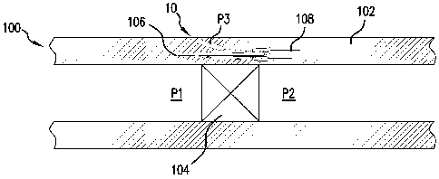
[0007] Figure 2 is a cross-sectional view of the pressure equalization valve
used for
equalizing pressure across a primary valve in a tubular string.
DETAILED DESCRIPTION
[0008] A detailed description of one or more embodiments of the disclosed
apparatus
and method are presented herein by way of exemplification and not limitation
with reference
to the Figures.
[0009] Referring now to Figure 1, a valve 10 is illustrated. The valve 10 is
arranged
to equalize pressures, designated P1 and P2 in the Figures, from each other
when the valve 10
is transitioned to an open configuration. The valve 10 includes a piston
member 12 movable
within a housing 14 between a closed configuration (shown in Figure 1) that
prohibits fluid
communication through the valve 10 and an open configuration (when shifted to
the right
with respect to the orientation of Figure 1) that enables fluid communication
through the
valve 10 and/or equalization of the pressures P1 and P2.
[0010] In one embodiment, the housing 14 is a wall of a tubular in a tubular
string.
For example, as shown schematically in Figure 2, the valve 10 is arranged in a
system 100.
Specifically, the valve 10 is disposed within a wall of a tubular at least
partially forming a
tubular string 102. The pressures P1 and P2 are present in the string 102 on
opposite sides of
a primary valve 104. The valve 10 is in communication with the pressures P1
and P2 via
passages 106 and 108 in the wall of the tubular string 102. In this way, the
valve 10 can be
arranged to equalize the pressures P1 and P2 on opposite sides of the primary
valve 104, e.g.,
prior to the primary valve 104 being opened. The primary valve 104 could be a
ball valve, a
flapper valve, or any other type of valve. In one embodiment, the valve 104 is
a subsurface
2
CA 02896835 2015-06-29
WO 2014/109856 PCT/US2013/074239
barrier valve, a subsurface safety valve, etc., and it is to be appreciated
that valves for any
other selective fluid communication task or operation could be used with or
for the
embodiments discussed herein. Advantageously, the use of the valve 10
minimizes or
eliminates the pressure differential across the primary 104, such that the
primary valve 104
does not become damaged, fail to operate properly, etc., due to large pressure
differentials
across the primary valve 104, the sudden high pressure inrush of fluid upon
opening the valve
104, etc.
[0011] Referring back to Figure 1, the valve 10 includes a sealing arrangement
configured to create various pressure areas on piston member 12 for operating
the valve 10
(discussed in more detail below). Specifically, the sealing arrangement
includes three sealing
features 16, 18, and 20 in the illustrated embodiment. The sealing feature 16
is disposed at a
first end 22 of piston member 12 that is exposed to the pressure Pl. The
sealing feature 18 is
arranged on a radial projection of the piston member 12 to present larger
pressure areas,
discussed in more detail below. Both the sealing features 16 and 18 are
illustrated as
dynamic elastomeric seal elements, although it is to be appreciated that fluid
could be sealed
in other manners or with other elements. The sealing feature 20 is arranged at
a second end
24 of the piston member 12 that opposite from the first end 22 and exposed to
the pressure
P2. The sealing feature 20 in the illustrated embodiment is a metal-to-metal
seal formed by a
tapered portion or poppet 26 of the piston member 12 entering a port 28 and
seating against a
shoulder 30 about the port 28. Again, seal elements or another manner of
sealing feature
could be used for or with the sealing feature 20. The sealing features 16, 18,
and 20 have
dimensions D1, D2, and D3, respectively.
[0012] The piston member 12 includes a fluid bypass port 32 at the first end
22 that
enables fluid to bypass the sealing features 16 and 18 and enter a chamber 34.
The chamber
34 is formed between the sealing features 18 and 20, and thus, the port 32
enables the
pressure P1 to act on piston member 12 at both of the sealing features 18 and
20. As a result,
when the valve 10 is in its closed configuration (as shown in Figure 1), the
pressure P1 acts
on the piston member 12 at all three of the sealing features 16, 18, and 20.
Specifically, the
pressure P1 acts in the opening direction on the sealing features 16 and 20,
and in the closing
direction on the sealing feature 18. When in the closed configuration, the
pressure P2 acts on
the piston member 12 only at the sealing feature 20 in the closing direction.
[0013] It is to be appreciated that by use of the bypass port 32 and by
balancing the
pressure areas on the piston member 12 defined by each of the sealing features
16, 18, and
20, the valve 10 will advantageously stay closed regardless of the pressure
value of the
3
CA 02896835 2015-06-29
WO 2014/109856 PCT/US2013/074239
pressures P1 and P2 that are exerted on the piston member 12. Specifically, if
a pressure area
36 for the sealing feature 18 in the chamber 34 (which enables the pressure P1
to act in the
closing direction) is set to be greater than a sum of the pressure areas 38
and 40
corresponding the sealing features 16 and 20, respectively, (which enable the
pressure P1 to
act in the opening direction), then the net effect of the pressure P1 will
always be in the
closing direction. Alternatively stated, the valve 10 is more firmly urged in
the closing
direction in response to increasingly larger values of the pressure P1 and
thus the valve 10 is
unable to be opened by the pressure Pl.
[0014] In more specificity, the pressure area 36 is determined as a difference
between
the areas associated with the dimension D2 and a dimension D4 of the portion
of the piston
member 12 extending through the chamber 34 (i.e., the area 36 is equal to
n((1/4)(D2)2¨
n((1/4)(D4)2); the pressure area 38 is determined as the area of the first end
22 (including that
of the port 32 due to the axial surface at the end of the port 32 that is
exposed to the pressure
P1), which corresponds to the dimension D1 (i.e., the area 38 is equal to
n((1/4)(D1)2); and the
pressure area 40 is determined as a difference between the areas of the piston
member 12
corresponding to the dimensions D3 and the dimension D4 (i.e., the area 40 is
equal to
n((1/4)(D3)2¨ n((1/4)(D4)2). In view of the foregoing, it is well within the
capabilities of one of
ordinary skill in the art to determine suitable values for the dimensions D1,
D2, D3, and D4
that enable the pressure P1 to have a net force in the closing direction as
discussed above.
[0015] Similarly to the pressure P1 above, since a pressure area 42 (equal to
n((1/4)(D3)2) of the piston member 12 at the second end 24 exposed to the
pressure P2 only
enables the pressure P2 to act in the closing direction, the pressure P2 also
cannot be used to
open the valve 10. In this way, if the valve 10 is used in the system 100 of
Figure 2 in which
the pressures P1 and P2 are internal tubing pressures, it can be said that the
valve 10 is tubing
pressure insensitive or unable to be activated by tubing pressure.
Additionally, it can be said
that the valve 10 is bi-directional as it is immaterial which of the pressures
P1 or P2 is the
greater pressure, as the valve 10 will not open due to either pressure and can
equalize in
either direction.
[0016] Since the valve 10 is specifically arranged to not open in response to
increases
in the pressures P1 and P2, the valve 10 must be opened in another manner. In
the illustrated
embodiment, a control assembly 44 of the valve 10 includes a control pressure
line 45 that is
in fluid communication with a control chamber 46 defined between the sealing
features 16
and 18. A control pressure P3 can be supplied via the line 45 to the chamber
46 in order to
urge the piston member 12 in the opening direction in order to open the valve
10 and enable
4
CA 02896835 2015-06-29
WO 2014/109856 PCT/US2013/074239
equalization of the pressures P1 and P2. That is, when shifted to the open
configuration, the
poppet 26 unseats from the shoulder 30, thereby opening the chamber 34 and the
port 32 to
the pressure P2. The port 32 provides communication between the pressures P1
and P2,
thereby enabling the pressures P1 and P2 to equalize.
[0017] In order to return the valve 10 to the closed configuration and
counteract
hydrostatic pressure in the line 45, a biasing or spring member 50 can be
included to urge the
piston member 12 in the closed direction. The biasing member 50 could be any
resilient,
spring-like, or elastically deformable member arranged to return the valve 10
to its closed
configuration. The line 45 could, for example, extend to surface to enable
operators to pump
a pressurized fluid downhole for controlling the operation of the valve 10.
The control line 45
could be equipped with a relief or bleed off valve in order to relieve the
hydrostatic pressure
in the control line 45, which can be substantial if the valve 10 is positioned
hundreds of feet
downhole in a borehole system.
[0018] The pressure P3 acts on a pressure area 48 of the member 12 defined as
a
difference between the areas associated with the dimensions D2 and D1 (i.e.,
the area 48
equal to n((1/4)(D2)2¨ n((1/4)(D1)2). The pressure areas 36, 38, 40, and 42
are determinable as
noted above. Thus, with knowledge of the pressures P1 and P2 (or expected
ranges for the
pressures P1 and P2), of the dimensions D1, D2, D3, and D4, and the
characteristics of the
biasing member 50, one can relatively accurately determine the pressure P3
needed to open
the valve 10. Advantageously, the control pressure P3 can be tied to the
control scheme used
for actuating the primary valve 104 in the system 100 of Figure 2. That is,
for example, the
control line 45 could supply hydraulic pressure to both the primary valve 104
and the valve
10. By setting the estimated pressure to open the valve 10 to be less than
that required to
open the primary valve 104, the equalization valve 10 automatically opens and
equalizes
pressure before the primary valve 104 opens. Furthermore, operators
controlling operation of
the valve do not need to perform any additional steps, as the valve 10 will
automatically open
before the primary valve 104 does. Of course, the control assembly 44 could
alternatively
include any device, mechanism, member, element, or combinations thereof that
enable a net
force to be exerted on the piston member 12 in the opening direction. Instead
of the
hydraulic embodiment illustrated, the control assembly could be any
combination of
magnetic, mechanical, electrical, etc. For example, the control assembly 44
could include
one or more electromagnets, a lead screw, a linear motor, etc., which could be
supplied with
power from an electrical cable replacing the control line 45. Regardless of
control scheme,
CA 02896835 2015-06-29
WO 2014/109856 PCT/US2013/074239
the operation of the valve 10 can be tied to the operation of the primary
valve 104, such that
the equalization valve always actuates with, preferably before, the primary
valve 104.
[0019] It is to be appreciated that any number of modifications could be made
to the
valve 10 or the system 100 while staying within the scope of the claims. For
example, in one
embodiment two of the valves 10 could be utilized in a modification of the
systems 100, with
the valves facing each other such that tubing pressure from both sides (P1 and
P2) is only
applied to metal-to-metal contact at the sealing feature 20, thereby
preserving the dynamic
seals (e.g., the sealing features 16 and 18). Additionally, the fluid passages
106 and 108
could be equipped with filters or screens for removing any undesirable solids,
e.g., sand or
debris, from disrupting operation of the valve 10 in the system 100.
[0020] While the invention has been described with reference to an exemplary
embodiment or embodiments, it will be understood by those skilled in the art
that various
changes may be made and equivalents may be substituted for elements thereof
without
departing from the scope of the invention. In addition, many modifications may
be made to
adapt a particular situation or material to the teachings of the invention
without departing
from the essential scope thereof. Therefore, it is intended that the invention
not be limited to
the particular embodiment disclosed as the best mode contemplated for carrying
out this
invention, but that the invention will include all embodiments falling within
the scope of the
claims. Also, in the drawings and the description, there have been disclosed
exemplary
embodiments of the invention and, although specific terms may have been
employed, they
are unless otherwise stated used in a generic and descriptive sense only and
not for purposes
of limitation, the scope of the invention therefore not being so limited.
Moreover, the use of
the terms first, second, etc. do not denote any order or importance, but
rather the terms first,
second, etc. are used to distinguish one element from another. Furthermore,
the use of the
terms a, an, etc. do not denote a limitation of quantity, but rather denote
the presence of at
least one of the referenced item.
6