Note : Les descriptions sont présentées dans la langue officielle dans laquelle elles ont été soumises.
CA 02897421 2015-07-07
WO 2014/114905 PCT/GB2014/000027
A REMOTE CONTROLLABLE SWITCH OPERATING DEVICE
Field of the Invention
The present invention relates to switching device. More particularly the
invention
relates to a switching device for switching an electrical appliance on and
off. The
s device is suitable for use in a domestic or office building, in a
vehicle, such as a
camper van, or in living quarters of a ship; and other locations where
electrical
_ appliances are commonly found.
Background
Many household and workplace electrical appliances in use are connected to a
power supply. They are turned on and off by connecting to and disconnecting
from
the power supply. Typically this is done manually by a user operating a manual
switch.
A manual switch is useful for turning on or off a light or an appliance
plugged into a
power socket. A person can usually see, or feel (if they are visually
impaired), by the
position or state of the switch, that the power supply is switched on or off,
when
obscured by darkness or furniture. People are familiar with using manual
switches.
In some situations it may be more convenient, or even safer, to be able to
control the
switch remotely. For example when turning off a light, it may be safer to do
so when
the desired location has been reached rather than having to make ones way
across a
room in darkness.
As most switches are permanently located, for example on walls, they can only
be
controlled from their fixed location, one at a time. This can also cause an
inconvenience, especially for people with limited mobility or who are bed-
ridden. For
example a light cannot be turned on and off if the mechanical switch is out of
reach to
such a person.
Another problem is in large houses, a person has to walk around the building
or
house turning all lights and appliances off one at a time, at night, typically
before
going to bed.
Because of the limitations of switches available in the prior art, appliances
tended to
be left switched on, so wasting energy or left switched on posing a risk of
electrical
fire or electrical accident. Appliances also tended to be left switched off
because a
switch to turn on the appliance could not be seen or found easily in the dark
or
because a timer switch had tripped.
Thus there is a need for a switch operating device which retains the
usefulness of a
1
CA 02897421 2015-07-07
= =
. WO 2014/114905PCT/GB2014/000027
MdflUdI SWItUfl and overcomes the aforementioned problems.
Prior Art
A number of patent applications have been filed in an attempt to resolve the
aforementioned or similar problems.
Chinese utility model CN 201 585 173 (YI et al) relates to a wireless lighting
switch,
which comprises a control panel and a far infra-red (IR) transmitter.
Similarly International patent application WO 2008 063 283 (SPIRA) discloses a
lighting control system comprising: a remotely-controllable load control
device, such
as dimmer switch.
in Remote controlled lighting was available, in the form of timer switches;
however
some required light fittings to be replaced with specialist parts which were
often
costly. Another problem with timer switches was that they were inflexible and
did not
permit any immediate control because the timings had to be preset.
The invention arose in order to overcome the problems associated with the
prior art
and to provide an improved switch operating device that overcomes the
aforementioned problems.
Summary of the Invention
According to the present invention there is provided a remote controllable
switch
operating device includes a receiver for receiving a control signal from a
remote
control device and an actuator which responds to the control signal in order
to turn a
switch on or off, characterised in that the switch operating device is
dimensioned and
arranged to retro-fit to a housing with an exposed switch and the actuator is
located,
so that in use, the actuator engages with the switch in order to turn on the
switch or
to turn off the switch, upon receipt of a corresponding control signal.
Preferably a switched interface comprises the housing, the switch, and
electrical
connector for an appliance so that advantageously the operating device
connects or
disconnects electricity to the electrical connector so as to turn it 'on' or
'off.
According to a second aspect of the present invention there is provided a
remote
controllable switch operating device including: a receiver for receiving a
control signal
from a remote control device and an actuator which responds to the control
signal in
order to turn a switch on or off, characterised in that at least a portion of
the switch is
exposed so as to permit manual operation of the switch.
Preferably the remote controllable switch operating device is dimensioned and
2
CA 02897421 2015-07-07
= =
, ayyq014/LI4IT;Ofit to a housing comprising the switch
arrangedPS4!õ%atilecV.Zival
operation.
There is ideally a provided an operating device for supplying a remote control
signal
to the switch operating device which is battery powered and is ideally
portable.
However, it is understood that mobile communication devices fitted with an
infra-red
communication port may be configured to act as a remote controller by
providing a
suitable signal. Such a mobile communication device may be a portable digital
assistant (PDA), a Blackberry (Trade Mark) mobile device, an i-Phone (Trade
Mark) or any similar device that is capable of operating according to a
computer
in programme to generate and transmit a suitable control signal.
Advantageously the remote controllable switch operating device provides a
manually
displaceable mechanical switch, preferably in the form of a rocker, turnable
knob or
toggle which is manually displaceable or repositionable. Ideally the operating
device
displaces the switch from one position and state (on or off) to another
position and
state (on or off) in accordance with a desired control signal. So that when
the switch
is being remotely operated the switch moves or is displaced in order to open
or close
a circuit.
Preferably the same switch that is manually operable by displacement or
repositioning is also remotely operable by the actuator acting in accordance
with the
control signal. Remote operation of the switch physically changes the switch
position. The change in position can be observed by a user who may operate the
switch manually.
As preferably the actuator physically displaces the switch upon turning the
switch 'on'
or 'off a user can see it is in the 'on' or 'off' position.
In a second embodiment the remote controllable switch operating device is
clamped
or connected to an exterior of a switch interface or housing. Preferably the
switch,
which is exposed on the switch interface, remains exposed or partially exposed
when
the remote controllable switch operating device is clamped into place. A user
can
turn the switch 'on' or 'off remotely without touching the switch. A user can
also turn
the switch 'on' or 'off manually by touching and manually displacing the
switch
because the switch is exposed.
In some examples of the second embodiment the remote controllable switch
operating device is clamped to a switch interface and covers the switch. In
this
instance a window or a light, light emitting diode (LED) or another indicator
is
provided on the remote controllable switch operating device so that the user
can see
that the switch has been displaced by turning it 'off and 'on'.
3
CA 02897421 2015-07-07
' WO 2014/114905 PCT/GB2014/000027
Advantageously the present invention provides a means for allowing remote
control
of electrical outlets, sockets, fasciae, or appliances. The remote
controllable switch
operating devices may be incorporated into such appliances either at
manufacture or
aftermarket.
In some embodiments the clamp consists of first and second clamp parts which
are
displaceable in use relative one to another. The clamp parts may be secured
with a
spring bias acting to force the clamp parts together or to urge the clamp
parts onto a
fascia or switch housing.
In other preferred embodiment the operating device is integrated into a
housing or
fascia so that components are hidden.
The operating device comprises a first component part which includes an
actuator
that is adapted to displace the switch. Optionally a second component part is
secured to an electrical back box, in this configuration the component parts
are
secured together in use.
In some such embodiments the second part may be screwed onto or into the back
box so as to push against the first part, wherein said first part is mounted
on or
comprises the fascia. Electrical connection may in addition be made from or
via the
second part. In other embodiments where the operating device is integrated
into the
fascia, or switch, the parts may be formed integrally or made to connect
inseparably
in use or after installation.
Advantageously in embodiments where the operating device is suitable for retro-
fit to
operate a pre-installed switch, the operating device is integrated in the
fascia so that
the fascia remains usable in standard localized format, wherein ideally the
operating
device is incorporated into a rear face of the fascia for example with no
impact on the
aesthetics of the fascia.
Ideally the actuator is arranged to displace the switch in such a manner that
the
position or state of the switch may be reversed or changed manually.
Advantageously the switch is operable via the remote controllable switch
operating
device from a remote location such as another room.
When the switching device is integral with a switch housing behind a fascia,
the
switch can be considered to be internally activated or deactivated, whereas
when
operated manually the switch may be considered to be exteriorly activated.
Ideally the control signal can be transmitted to ranges of up to several
hundred
metres so as be able to control the operating device even when outside of a
home,
4
CA 02897421 2015-07-07
WO 2014/114905PCT/GB2014/000027
=
for example to switch on lights when arriving home.
Preferably the remote controller is incorporated into existing hardware, which
may be
operable or function using software or firmware. For example therefore in some
embodiments the remote controller may be provided by or as a function of a
'smart-
s phone', such as an 'APP' or in a universal controller.
Ideally the operating device and remote controlled are first synchronised
together so
as to be able to send and receive information between the two. Once
synchronised
the operating device and remote controller may communicate by transmission and
acceptance of wireless signals.
Typically fasciae project from walls on which they are mounted so as to be
proud of
the wall. Therefore for externally mounted or retro-fit embodiments the
operating
device parts may be shaped so as to bridge, encompass or cover at least part
of the
fascia ideally by having extended end portions that hook over the fascia sides
so as
to clamp or secure to the fascia without requirement for an additional means
of fitting.
Preferably the operating device vertically traverses the fascia so as to be
positioned
over the switch or switches. It is envisaged that the buttons may remain
depressed
when pressed so as to visually indicate what state the device is in for
example, on or
off.
Advantageously the operating device may be adapted to fit single and double
fasciae. For example for double switches additional buttons may be included to
control the second switch.
Preferably the operating device for the single switch includes an extended
side edge
so as to fit to the fascia top, bottom (as in the double adapter) and side.
Typically as the single operating device is offset, so as to cover the single
switch, the
adapter enclosing the side as well as the top and bottom may provide better
fit and
neater appearance.
In devices that are retro-fitted to the fascia an integral battery provides
the means of
power to control the device. Yet further embodiments which connect to the
electrical
current may include a false front and/or may allow the device to provide a
socket or
physical switch.
Preferably the operating device is inbuilt, embedded or permanently fastened
to the
fasciae, for example so as to allow the operating device and system to operate
in
fasciae that may not accept the spring fit mechanism. In some embodiments the
operating device is fitted around fasciae, for example by a resiliently
deformable
member, flexible or elastic strap.
5
CA 02897421 2015-07-07
WO 2014/114905PCT/GB2014/000027
In prererreu embodiments actuator moves quickly in order to move me swItcn
witnout
protracted movement against the connection means.
Preferably the operating device may also operate from mains power, removing
and
reducing requirement for batteries.
Preferably the operating device is included in a fascia, wherein the actuator
acts on
the switch to connect or disconnect electrical current to an electrical
circuit or outlet.
The invention will now be described, by way of example only, with reference to
the
accompanying drawings in which:
Brief Description of the Figures
1.0 Figure 1 shows a schematic view of a room wherein a user operates the
remote
controllable switch operating device to turn on and off a light and a
television;
Figure 2 shows a schematic view of a first embodiment of the device arranged
within
a single part;
Figure 3 shows a schematic view of a second embodiment of the device arranged
as
two parts securable to a housing comprising a switch;
Figure 4 shows an isometric view of a first example of the second embodiment
of the
operating device in use on a fascia;
Figure 5 shows a rear isometric view of the first example of the second
embodiment
of Figure 4 in use on a fascia;
Figure 6 shows an isometric view of a second example of the second embodiment
of
the operating device in use on a fascia;
Figure 7 shows an isometric view of a carcass of the second example of the
second
embodiment shown in Figure 6;
Figure 8 shows a rear isometric view of a the first embodiment of the
operating
device integrated into a fascia;
Figure 9 shows an exploded isometric view of a third example of the second
embodiment of the operating device;
Figure 10 shows an isometric view of an embodiment of the remote controller;
and
Figure 11 shows a rear isometric view of the second example of the second
embodiment of Figure 6 in use.
6
CA 02897421 2015-07-07
.4
ailii26113t9gription of Preferred Embodiments of the invenVo
l'iG-B2014/000027
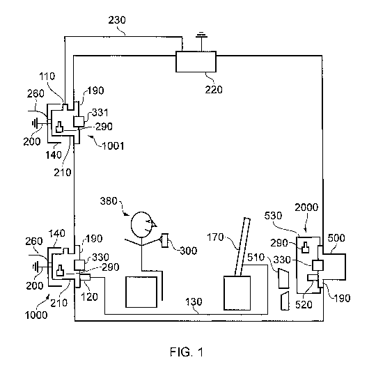
Figure 1 shows a schematic view illustrating the remote controllable switch
operating
device in use.
A user 380 is sitting in a chair and holding a remote controller 300. The user
uses
the remote controller to provide a control signal two turn on and off the
remote
controllable switch operating device 1000 by which electricity is supplied to
the user's
television 170.
The user 380 also uses the remote controller 300 to provide a control signal
that
turns on and off the remote controllable switch operating device 1001 by which
electricity is supplied to a light 220 in the room.
An appliance wire 130 is connected to the television 170. The appliance wire
has a
plug 120 that is plugged into a socket in the remote controllable switch
operating
device 1000.
If the user 380 prefers they can manually operate the switch 330 to turn on
and off
the electricity supplied to the television. The switch 330 is exposed to the
user so
that the user can move it.
If the user 380 uses the remote controller 300 to turn off or on the
electricity to the
television 170, the switch 330 is physically moved by an actuator within the
remote
controllable switch operating device 1000.
A light wire 230 is connected to the light 220. The light wire is also
connected to an
appliance connector on the remote controllable switch operating device 1001.
The user 380 has a choice of either manually operating the switch 331 on the
operating device 1001 to turn on and off the electricity supplied to the light
220 or
using the remote controller 300 to turn on and off the electricity supplied
the light. If
the user chooses to use the remote controller to turn the light on or off the
switch is
physically moved by an actuator within the operating device.
Each operating device 1000, 1001 has a receiver 290 that receives a control
signal
provided by the remote controller 300. The remote controller 300 provides a
wireless
signal and the receiver 290 is a wireless receiver. A portion of the receiver
may be
external to the operating device so as to receive clearly either an
electromagnetic
radio signal, a visible or invisible light signal, or an audible or inaudible
sound signal
that commands the operating device to turn the switch 330, 331 on or off.
The operating device 1000, 1001 has a housing 210 that is dimensioned and
arranged to be received by an electrical back box 140 used for building
electrical
7
=
CA 02897421 2015-07-07
= =
WO 2014/114905
PCT/GB2014/000027
wiring.
The housing 210 comprises a mains power connector which is connected to a
power
cable 260 and a ground cable 200.
Figure 2 shows a schematic of the first embodiment of the operating device. A
switch
330 protrudes through a fascia 190. The switch 330 is exposed to a user who
can
see and touch the switch 330 where it protrudes through the fascia 190.
The user displaces the switch 330 to move electrical contacts 340. By bringing
the
contacts 340 into contact with the terminals of an electrical circuit 180, the
electrical
circuit 180 is closed. The user displaces the switch 330 to open and close the
circuit
lo 180.
As shown in Figure 2, the electrical circuit 180 connects a power supply
connector
260 to an electrical appliance connector 110. The appliance connector 110 is a
socket suitable for receiving plug 120 as the one illustrated in Figure 1 at
the end of
the television appliance wire 130. The power supply connector is adapted to
connect
to a power cable 260. The power cable 260 is part of mains electrical wiring
in a
building. A terminal of the socket 110 is also connected directly by the
circuit 180 to
a ground cable 200. A power supply connector 270 is arranged to simplify
connection
of the operating device to the power cable 260 and the ground cable 200.,
When the user moves the switch 330 to close the circuit 180 the appliance
connector
110 is turned on. An appliance 170 having a plug 120 in appliance connector is
thereby connected to the mains electrical supply. When the user moves the
switch
330 to open the circuit 180, the appliance connector 110 is electrically
disconnected
from the power cable 260.
The remote controllable switch operating device 1000 is protected by a housing
210
and covered by a fascia 190. The housing and the fascia are shown as separate
components in Figure 2, but they can be a single piece.
When the operating device 1000 is installed into a building wall, the fascia
is
arranged to face a user.
A receiver 290 enables the operating device to detect control signals. The
receiver
290 is electrically connected to a solenoid relay 320. The solenoid relay is
connected
to the power supply connector 270 and also connected to a solenoid 310.
The solenoid 310 drives a displaceable member 160 and so together are an
actuator
100. The skilled person could substitute another type of electro-magnet as the
actuator.
8
CA 02897421 2015-07-07
TrVcigrjabegle member 160 holds the switch 330 so that warTia,
Be 4I
NcligiSTc2jable
member moves the switch 330 also moves. Thus the switch 330 is displaced by
operation of the actuator 100.
Although typically the actuator 100 comprises a solenoid 310 and the circuit
180 is
opened and closed by the actuator 100 displacing or depressing a switch 330 in
the
form of a button or a rocker, other types of electro-mechanical transducers
are known
and may be substituted. A motor with a worm gear is another example. A force
is
generated by the solenoid 310, which may be a linear solenoid as shown in
Figure 2.
The solenoid creates an electromagnetic field that moves the actuator or a
plunger
lo 160 in order to press the switch 330. Typically the plunger 160 moves
parallel to the
switch 330 so as to engage with and push up the switch when extended and pull
the
switch down when retracted.
In some examples of the operating device 1000, 2000 there are actuator buttons
on
the fascia 190 or the exterior casing 530 to operate the actuator so as to
turn the
switch 330 on and off. In Figure 4 an 'on' button 250 and an 'off button 251
are
shown. The actuator button is also exposed from the fascia and the solenoid
may
also be activated manually by pressing the actuator button.
Activation of the actuator in preferred embodiments produces a controlled
linear force
to toggle the switch from on to off, typically mimicking an action of a user
pressing the
switch. Thus remote activation via the receiver 290 mimics the action of a
user's
manual displacement of the switch 330.
Ideally the solenoid 310 may be activated by the signal received from the
remote
controller 300 which passes the signal to the operating device. The signal may
be
envisaged to be transmitted by infra-red, shortwave radio frequency, wireless
connectivity or inter-machine operability such as Bluetooth (Trade Mark).
Scrutinizing Figure 2 in detail it is evident that a user 380 turns the switch
on remotely
by commanding a remote controller 300 to send a wireless 'on' command signal.
The 'on' signal is detected and interpreted by the receiver 290. The receiver
290 is
electrically connected the solenoid relay 320 and activates the relay to
operate the
actuator 100 to move the switch 330 to the closed position. The electrical
contacts
340 then close the circuit 180 to provide electricity to an appliance 170
connected to
the appliance connector 110.
A user can also see that the switch has been moved to the 'on' position
because the
switch is exposed where it protrudes through the fascia 190.
A user 380 turns the switch off remotely by commanding a remote controller 300
to
send a wireless 'off command signal. The 'off signal is detected and
interpreted by
9
CA 02897421 2015-07-07
ti)rigit411119n0. The receiver 290 is electrically connected thecOgrigierra2;
320
and activates the relay to operate the actuator 100 to move the switch 330 to
the
open position. This disconnects the electrical contacts 340 from the circuit
180 to
prevent electricity flowing to the appliance connector 110. A user can also
see that
the switch 330 has been moved to the 'off position because the switch is
exposed
where it protrudes through the fascia 190.
The signal is received by the receiver 290 which comprises or is electrically
connected to a signal interpretation circuit which may be on a printed circuit
board
(PCB). The interpreted signal is used to produce the desired response, for
example
io to turn on or off the switch 330.
The remote controller 300 in some examples is a familiar rectangular object or
casing
as shown in Figure 10. The remote controller is equipped to send a
transmission to
the operating device when activated and including its own power supply in the
form
of the battery. It is envisaged that the remote controller may be handheld or
wall
mounted. The remote controller 300 comprises an 'on' button 252 and an 'off
button
253. In another example of the remote controller 300 it comprises a microphone
by
which it is voice activated. The remote controller wireless transmits
the
corresponding 'on' or 'off command signal when the corresponding button is
pressed
preferably by radio waves. The interpretation circuit identifies and
interprets the
signal triggering activation of the solenoid 310 so as to engage the plunger
160 which
in turn depresses the switch 330.
In an alternative configuration of the remote controlled switch operating
device 1000,
the user's voice acts as the remote controller. The receiver 290 is an audible
sound
detector and the interpretation circuit interprets the words 'on' and 'off.
The remote controller 300 comprises syncing buttons 362 and 363. Depressing a
sync button on the remote controller causes it to issue wireless sync signal
that is
detected by the receiver 290 in the operating device.
To make the remote controller 300 operate a particular remote controller
switch
operating device 1000, 1001, 2000, the sync button 360 on the operating device
is
depressed and simultaneously the sync button 362 is depressed on the remote
controller. Both buttons are held down for a predetermined time.
A sync circuit 370 shown in Figure 2 is activated by depressing the sync
button 360.
The sync circuit is electrically connected to the receiver 290. Depressing the
sync
button 360 on the operating device 1000 while the sync button 362 is depressed
causes the operating device 1000 and the remote controller 300 to by synced.
Once
the remote operating device 1000 and the remote controller are synced, the
syncing
circuit 370 permits 'on' and 'off commands to be transmitted by the receiver
290 to
=
CA 02897421 2015-07-07
= =
WO 2014/114905
PCT/GB2014/000027
the soienota relay 320, so the remote controller 300 operates me switcn -
.5:5U. To
unsync the remote controller and the operating device the unsync buttons 361,
363
on the remote controller and operating device are simultaneously depressed for
a
predetermined time.
If one user remotely alters the position of the switch 330 while another user
is
manually altering the position of the switch, the actuator will recognize this
and will
allow the remote command signal to be over ridden by the user moving the
switch
330 manually - this is to avoid breakage etc - actuator recognizes the force
acting
against it and will therefore stop resisting any manually imposed moving of
the switch
330.
The arrangement of the appliance connector 110, power supply connector 270,
circuit 180, electrical contacts 340, switch 330, actuator 100, solenoid relay
320,
receiver 290, housing 210, fascia 190 and so forth are shown for example in
Figure 2
for a first embodiment of the device. An arrangement of these components has
been
described in the paragraphs above. This arrangement also generally applies to
other
embodiments where practical except where the other embodiments are described
as
differing from the first.
A second embodiment of the remote controllable switch operating device is
shown in
Figure 3, Figure 4, Figure 5, Figure 6, Figure 7, Figure 9, and Figure 11.
Figure 8
shows a hybrid embodiment of the first and second embodiments in combination.
Figure 3 shows a schematic view of the second embodiment of the remote
controllable switch operating device 2000.
Figure 4 shows a first example of the second embodiment of the operating
device
2000 attached to a fascia of a switched interface 500. The switched interface
500
comprises a switch 330 which turns off and on electrical power to an appliance
connector 110. Generally the appliance connector is a plug socket as shown in
Figures 4 and 6.
Homes and offices are typically built with switch interfaces 500 which
comprise a
manually operable switch 330 to turn on and off electricity to a socket 110 in
the
interface or to turn on and off electricity to an appliance connector 110 that
is
connected to a light wire 230.
The second embodiment of the operating device 2000 is an external embodiment
because it clamped the exterior of a switch interface 500. The second
embodiment
of the invention 2000 is arranged to clamp onto the fascia 190 of the switch
interface
500.
11
CA 02897421 2015-07-07
. .
' WO 2014/114905PCT/GB2014/000027
In une example of the second embodiment shown particularly in r igure i, r
igure 4,
and Figure 6 the operating device 2000 comprises a first part 10 adapted to be
secured in use to a second part 20; wherein the parts 10, 20 are adaptable to
secure
the operating device 2000 to the fascia 190 of the housing of the switch
interface
500. Thus the operating device 2000 is dimensioned and arranged to retro-fit
to the
part of the housing of the switch interface 500 which is the fascia 190. The
fascia
comprises the switch 330.
The second embodiment of the operating device 2000 is typically attached to
the
fascia 190 by means of the sprung mechanism 150. By the sprung mechanism 150,
lo the second part 20 is displaceable relative to the first part 10. Both
parts may be
pulled apart by stretching the spring so as to enable the parts to traverse
the fascia.
The clamping mechanism 150 spring 50 draws the two parts 10, 20 together,
thereby
clamping the operating device 2000 to the fascia 190 of switch interface 500
housing.
The second embodiment of the operating device 2000 includes with the first
part 10,
a receiver 290 for receiving a control signal and an actuator 100 which
responds to
the control signal in order to turn the switch 330 on and off.
The switch 330 is exposed so that it is manually operable by the user. When
the
operating device 2000 is clamped to the fascia 190 for use, the actuator 100
is
located so that it engages with the switch 330 in order to turn the switch 330
off or on
upon receipt of a corresponding control signal.
In external embodiments of the operating device 2000 arranged for use exterior
to
the switch interface 2000, the operating device 2000 typically comprises a
casing
530 that houses at least two sets of buttons for controlling the operating
device
2000. One set of buttons enables syncing of the operating device with a remote
controller 300. The second set of button is for manual operation of at least
one
switch 330. The casing 530 houses a solenoid which produces motion when
activated so as to toggle switch 330 between on and off. The casing 530 houses
an
interpretation circuit on a printed circuit board (PCB) to receive and
interpret signals
received by the receiver 290 also housed by the casing 530.
In the second embodiment of the operating device 2000, there is at least one
battery
inside the casing 530.
The second embodiment of the operating device 2000 cooperates with a remote
controller 300 capable of transmitting a signal to the operating device to
remotely
operate the switch 330.
The second embodiment of the remote controllable switch operating device 2000
works for a user 380 as the first embodiment does. In the illustration of
Figure 1 the
12
k
CA 02897421 2015-07-07
. .
uave? Conlais a first embodiment of the operating device 100i?
Pu2rin Vi7d off
electricity to a television. The use also commands a second embodiment of the
operating device 2000 to turn on and off electricity to an electric socket
which is
connected to a radio wire plug 520 so as to turn on and off a radio 510.
s The arrangement of the receiver 290, solenoid relay 320, actuator 100,
solenoid 310,
displaceable member 160 inside the casing 530 of the second embodiment is as
described for the first embodiment except that the battery 145 provides power
for the
actuator 100, receiver 290, and solenoid relay rather than power cable 260 in
the first
embodiment.
lo Ideally two sets of buttons are positioned in different locations user
accessible
locations on the exterior of the operating device. Activation buttons are
positioned on
the face of the operating device, above the fasciae so as to be easily
accessible. One
set of activation controls or buttons enable the operating device 1000, 2000
to
synchronize with the remote controller 300. They are positioned on the
operating
15 device side where they are clearly distinguishable. In some further
embodiments
such activation controls may be permanently open or may have a time delay open
period during which synchronization may be achieved. In such embodiments the
controls may be hidden in use.
In preferred embodiments the operating device and remote controller may be
formed
20 of same or similar materials as that of the fasciae so as to be discrete
such as
synthetic plastic or brushed stainless steel.
The invention has been described by way of examples only. Therefore, the
foregoing
is considered as illustrative only of the principles of the invention.
Further, since
numerous modifications and changes will readily occur to those skilled in the
art, it is
25 not desired to limit the invention to the exact construction and
operation shown and
described, and accordingly, all suitable modifications and equivalents may be
resorted to, falling within the scope of the claims.
13