Note : Les descriptions sont présentées dans la langue officielle dans laquelle elles ont été soumises.
CA 02897726 2015-07-09
WO 2014/142813
PCT/US2013/030550
1583z.-0045W01/ 2012-IP-057674
Fiber Reinforced Sealing Element
TECHNICAL FIELD
[0001] This disclosure relates generally to a sealing ;dement for a rotating
control
device (RCD) used in rotary drilling systems, and particularly to a fiber
reinforced
sealing element for the RCD.
BACKGROUND
[0002] During drilling, an earth-boring drill bit is typically mounted on the
lower
end of a drill string and is rotated to form a wellbore by rotating the drill
string. During
this process erratic pressures and uncontrolled flow known as formation "kick"
pressure
surges can emanate from a well reservoir, potentially causing a catastrophic
blowout.
Because formation kicks are unpredictable and would otherwise result in
disaster, flow
control devices known as blowout preventers ("BOPs") are required on most
wells drilled
today. BOPs are often installed redundantly in stacks, and are used to seal,
control and
monitor oil and gas wells.
[0003] One common type of BOP is an annular blowout preventer. Annular BOPs
are configured to seal the annular space between the drill string and the
wellborc annulus.
Annular BOPs are typically generally toroidal in shape and are configured to
seal around
a variety of drill string sizes, or alternatively around non-cylindrical
objects such as a
polygon-shaped Kelly drive. Drill strings formed of drill pipes connected by
larger-
diameter connectors can be threaded through an annular BOP. Annular BOPs are
not
designed to be stationary while maintaining a seal around the drill string as
it rotates
during drilling because rotating the drill string through an annular BOP would
rapidly
wear it out, causing the blowout preventer to be less capable of sealing the
well.
[0004] In some drilling operations, a rotating control device (RCD) located on
top
of the BOP stack is used in managed pressure and underbalanced drilling to
interface
between high and low pressure regions of drilling operations. During this type
of drilling
the well bore is held at pressures that are well above atmosphere which
creates the
problem of how to get the drill pipe into the well without the loss of well
pressure and
1
CA 02897726 2015-07-09
WO 2014/142813
PCT/US2013/030550
15834-0045W01/ 2012-1P-057674
fluid. The RCD forms a seal between the well bore and the drill pipe so that
the drill
string can move vertically and rotationally without the loss c f well
pressure.
[0005] The key component in the RCD, which allows for the separation of high
and low pressure regions, is the RCD sealing element. The RCD sealing element
is
comprised of a core and an elastomeric body. The core is molded into the
upstream end
of the elastomeric body and is used to fasten the element to the RCD. Cores
can be made
in many shapes and sizes and fabricated from many materials. For example, an
RCD core
can be made from steel and is referred to as a cage. An RCD sealing element
may also be
referred to as a stripper rubber.
[0006] A drill string of varying diameter is passed through the center of an
RCD
sealing element. RCD sealing elements are currently made so that the inside
diameter of
the RCD sealing element is smaller than the smallest outside diameter of any
part of the
drill string passed through it. As the various parts of the drill string move
longitudinally
through the interior of the stripper rubber a seal is continuously maintained.
[0007] RCD sealing elements seal around rough and irregular surfaces such as
those found on a drill string and arc subjected to conditions where strength
and resistance
to wear are very important characteristics. However, RCD sealing elements
often have a
short life expectancy, especially when they are used in wells that have high
well bore
pressures. Loads exerted on the outside of the element body by the high
pressure region
of the well cause the element to deform and press against the drill pipe. High
frictional
loads result from the pipe being stripped through the element as it is
deformed against the
drill pipe. High pressures in the well can accelerate RCD sealing element
failure.
Common modes of RCD sealing element failure include side wall blow through,
vertical
and horizontal cracking and chunking away of the interior region of the
sealing element
body also known as "nibbing".
[0008] Conventional prior art sealing elements in rotating control devices
(RCDs)
tend to split or experience chunking when encountering harsh loading
conditions due to
poor tear resistance. Further, over time the sealing element may become worn
and may
become unable to substantially deform to provide a seal around the drill
string.
2
CA 02897726 2015-07-09
WO 2014/142813
PCT/US2013/030550
15834-0045W01/ 2012-1P-057674
Consequently, the sealing element must be replaced, which may lead to down
time during
drilling operations that can be costly to a drilling operator.
DESCRIPTION OF DRAWINGS
[0009] The details of one or more embodiments of the disclosure are set forth
in
the accompanying drawings and the description below.
[00010] FIG. 1 is a cross sectional view of a rotating control
device.
[00011] FIG. 2 is a cross sectional view of a rotating control device
scaling
element in the rotating control device of FIG. 1.
[00012] FIG. 3 is a schematic view of a fiber-reinforced elastomer to
be
used in a rotating control device sealing element.
[00013] FIG. 4 is a cross sectional view of a rotating control device
sealing
element comprising a fiber-reinforced elastomer.
[00014] FIG. 5 is a cross sectional view of a rotating control device
sealing
element comprising fiber-reinforced elastomers of varying fiber concentration.
DETAILED DESCRIPTION
[00015] In the rotating control device (RCD) sealing element of the
present
disclosure the body comprises the majority of an RCD device and is the
component
responsible for creating a seal between the drill pipe threac ed through the
RCD and the
interior of the wellbore below the RCD. Materials for making the elastomeric
body
include polyurethane, natural rubber, nitrile rubber and butyl rubber. In use,
the RCD
sealing element is held inside the RCD and the drill pipe stabs through the
RCD sealing
element when it enters the RCD, creating an interfacial seal capable of
separating the
high pressure region of the well bore from the atmospheric pressure region of
the rig
floor. The interfacial seal is created when the drill pipe enters the RCD
sealing element
and deforms the inner diameter of the RCD sealing element to fit over the
larger diameter
of the drill pipe. While attached, the drill pipe penetrating the RCD sealing
element is
capable of vertical motion as well as rotational motion. The RCD sealing
element is also
able to expand to fit over tool joints as new sections of drill pipe are added
to the drill
string.
3
CA 02897726 2015-07-09
WO 2014/142813
PCT/US2013/030550
15834-0045W01/ 2012-IP-057674
[00016] This
disclosure also relates to a method of improving the material
properties of the elastomeric RCD element body by introducing a fibrous
reinforcing
material into the elastomer. During the preparation of the elastomer raw
material, fibers
can be added so that the performance characteristics of the finished element
are altered.
Elements that have been molded with reinforced elastomer can have improved
strength,
resistance to tear and abrasion while still exhibiting good elongation.
[00017] The
elastomer used to form the RCD sealing element of the present
invention contains polyurethane. Rubber and polyurethane do not have identical
material
properties. Natural rubber has excellent elastic memory, that is it will
return its original
shape after being compressed or stretched. Polyurethane has a substantially
lower
memory than rubber. Compression Set is a measure of memory. In one
implementation,
the polyurethane described herein has a compression set of approximately 62%
while
rubber compounds can have a compression set of 6% or lower. Polyurethane is
affected
by temperature differently than rubber. Polyurethane breaks down in the
presence of
water while remaining strong in the presence of oil, rubber is the opposite.
[00018] The
molding process is significantly different between rubber and
cast polyurethane; rubber is injected into a mold with high pressure and high
temperature
while cast urethane is simply poured into a mold and heated in an oven. Since
the
molding process is different the technique for adding reinforcing fibers is
also different.
Since, unlike with rubber molding the mold is not filled under high pressure,
fibers can
be connected to the inside of the empty mold and oriented horizontally,
vertically,
radially or in any combination desired prior to the filling of the mold.
Concentration and
placement of the reinforcing fibers in elastomers containing polyurethane can
be
carefully controlled, thus allowing regions of the element to be targeted with
more
reinforcing material and other regions to be given very little or no
reinforcing material.
[00019] A major
limitation to the capabilities of prior art RCDs is the
amount of well pressure at which they can they can operate, with the
capabilities of
current RCD sealing elements as a major limiting factor. An advantage of the
RCD of
this disclosure is providing an RCD sealing element that can operate at higher
pressures
than current RCD sealing elements.
4
CA 02897726 2015-07-09
WO 2014/142813
PCT/US2013/030550
15834-0045W01/ 2012-IP-057674
[00020] Often RCD
sealing element life is short which can result in
frequent element replacement during drilling operations. It is well-known that
rig time
can be very expensive, especially when drilling operations are performed in
deep water.
Typical deep water daily rig costs can range between $400,000 and $900,000 a
day. If an
RCD sealing element can last for drilling a complete borehole section, the
approximate
two hours rig time for an element change out equates to a rig downtime saving
of
$33,000 to $75,000. Improving element life with an element with improved life
and
durability according to this disclosure will reduce costs. This cost saving
will be achieved
by fewer elements being required to complete an operation, as well as saving
in much
more costly rig down time. Improving element life will also result in a
reduction of
nonproductive time for the rig since the rig must be shut down each time an
element is
changed out.
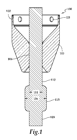
[00021] Referring
to Figure 1, one implementation of the RCD 100
includes an RCD sealing element 105 (also sometimes referred to in the art as
a "stripper
element" or "stripper rubber"). The RCD sealing element 105 acts as a passive
seal that
maintains a constant barrier between the atmosphere above and wellbore below.
An
interior surface 106 of the RCD sealing element 105 seals against a drill
string 110. The
drill string 110 extends from a drilling rig (not shown) through the sealing
element 105
and into the wellbore (not shown).
[00022] A drill
string typically includes multiple drill pipes connected by
threaded connections located on both ends of the drill pipes. Although the
threaded
connections may be flush with outer diameter of the drill pipes, they
generally have a
wider outer diameter. For example, as shown in Figure 1, drill string 110 is
formed of a
long string of threaded pipes 103 joined together with tool joints 115. The
tool joints 115
have an outer diameter 116 that is larger than the outer diameter 111 of the
pipes 103. As
the drill string is longitudinally translated through the wellbore and the RCD
100, the
RCD sealing element 105 squeezes against an outer surface of the drill string
110,
thereby sealing the wellbore. In particular, the inner diameter of the RCD
sealing element
105 is smaller than the outer diameter of the items passed through (e.g.,
drill pipes, tool
joints) to ensure sealing.
CA 02897726 2015-07-09
WO 2014/142813
PCT/US2013/030550
15834-0045W01/ 2012-IP-057674
[00023] A side
view of an exemplary RCD sealing element 105 is shown in
Figure 2. The RCD sealing element 105 has a base end 120 and a nose end 130.
The base
end 120 is typically attached to a mandrel (not shown) running through the
center of the
bearing assembly, however it could also be attached to a stripper housing that
does not
include a bearing. The mandrel is attached to the bearing housing via two sets
of
bearings. The element is then screwed onto the mandrel or bolted to the
mandrel; this
allows the element to rotate with the drill string during drilling operations.
For example,
holes 121 are provided for set screws to lock the element to he mandrel once
the element
has been threaded onto the mandrel. However there are muLiple other techniques
used to
mount the RCD sealing element to the RCD. This disclosure shall not be limited
to this
style of core but rather encompass all styles of core.
[00024] The nose
end 130 has an inner diameter 134 that is smaller than the
inner diameter of the base end 120 to provide a tight seal against the drill
string 110. The
outer diameter 122 of the base end 120 may be larger than the outer diameter
132 of the
nose end 130. Similarly the inner diameter 124 of the base end 120 may be
larger than the
inner diameter 134 of the nose end 130.
[00025] Prior art
RCD sealing elements are often made from of a single
elastic material which is flexible enough to deform to fit around and seal the
varying
diameters. Sealing element material may include but not be limited to natural
rubber,
nitrile, butyl or polyurethane, for example, and depends on the type of
drilling operation.
The RCD sealing element 105 of the present disclosure is made from a
polyurethane
based elastomer and is flexible enough to deform to fit around and seal the
varying
diameters of drill pipe 110 (e.g., diameters 111and 116 shown in Figure 1).
[00026] To alter
the performance characteristics of various RCD sealing
element body materials, the addition of reinforcing fibers of many kinds and
sizes may be
used. Fibers may include but are not limited to cotton, polyester, glass fiber
and polyvinyl
alcohol (PVA). Fibers may be of varying deniers and lengths and may be
combined in
any combination of denier and length. For example, an elastomer may be
reinforced with
fibers of uniform length and varying denier or an elastomer may be reinforced
with fibers
of varying length and uniform denier. Any combination of length and dernier is
6
CA 02897726 2015-07-09
WO 2014/142813
PCT/US2013/030550
15834 -0045W01/ 2012-IP-057674
permissible. In one embodiment, fibers may have a length of 1/8" to 5" and a
denier of
1200 to 1800.
[00027] As shown
in Figure 3, reinforcing fibers 205 can be added to the
elastomer raw material 210 to form a resultant composite material 200. This
composite
material 200 can be comprised of both uniformly distributed fibers and non-
uniformly
distributed fibers. Fibers 205 can be randomly oriented, or may be non-
randomly oriented
(i.e., oriented radially, oriented longitudinally, or oriented at some other
angle or
combination of angles).
[00028] The
concentration of reinforcement fibers 205 within the elastomer
material 210 can be varied to alter the properties of the composite material
210, allowing
for the customization of element material properties. For example, as shown in
Figure 4,
an RCD sealing element 250 may be molded with an elastomer that has a uniform
concentration 255 of fibers throughout. Any fiber concentration is
permissible, although
fiber concentration ranging from 1% to 20% is preferred. Element properties
that will be
altered by the addition of reinforcing fibers include but are not limited to
the following:
tensile strength, elongation, stress-strain modulus, tear strength,
compression set and
Taber abrasion.
[00029]
Alternatively, an RCD sealing element may be molded with an
elastomer material that has a non-uniform concentration of reinforcing fibers
along the
length (i.e., along a longitudinal or axial axis) of the RCD saling element.
For example,
shown in Figure 5, an RCD sealing element 270 has a higher concentration of
reinforcement fibers at its base 320 and a lower concentration of fibers at
its nose 330.
Any combination of fiber concentration is permissible. For example, more than
two
concentrations (i.e., three different fiber concentrations) are shown in
Figure 5: a region
with high concentrations of fiber reinforcement 272, a region with moderate
concentrations of fiber reinforcement 274 and a region with low concentrations
of fiber
reinforcement 276.
[00030] In a
varying fiber concentration RCD sealing element 270, each
region of fiber reinforced element material exhibits material properties are
different from
the other regions. The particular material properties can be selected to
optimize
7
CA 02897726 2015-07-09
WO 2014/142813
PCT/US2013/030550
15834-0045W01/ 2012-IP-057674
performance of different regions of the RCD sealing element 270. For example,
resistance to pressure is a critical material property needed at the base end
320.
Additional tensile and compressive strength near is required near the base end
320 for
resisting the tendency of the RCD sealing element 270 to blow out when high
pressure
builds on the exterior surface of the RCD sealing element 270. To increase
strength, a
high concentration of fibers 272 is used in the base end 320 of the RCD
sealing element
270. Resistance to deformation resulting from external pressure is also
essential to the
long life of RCD sealing element 270. Since the inner diameter at the base end
320 is
much larger than the ID at the nose end 330 the amount of elongation required
at the base
end 320 is much less than the amount of elongation required at the nose end
330. Since
high elongation is not required in the base section 320 a higher concentration
of fibers
can be used, for example 20%, thus giving increased strength and wear
resistance. In the
middle section 274 moderate elongation is required so a concentration of
approximately
5-10% may be used to increase strength and wear resistance while allowing for
required
elongation. In the nose section 276 where the greatest elongation is required
and wear
resistance is less important a lower concentration of approximately 1-5% can
be used.
[00031] The nose
end 330 of the RCD sealing element 270 requires greater
flexibility in order for the smaller inner diameter 334 of the nose end 330
(compared to
the wider diameter 324 of the base end 320) to deform around the diameters of
the
wellbore components passed through (e.g., drill pipe diameter 111, tool joint
diameter
116). Lower concentration fibers 276 enhance wear resistance but still allow
deformation
or elongation. Preferably the fibers in the nose area 272 have a concentration
276 ranging
between about 1% to 20%. The result is an the RCD sealing element 270 which
has a
higher resistance to pressure as well as longer wear in the area that contacts
the wellbore
components.
[00032] In one
embodiment, fibers are added to the liquid polyurethane and
the mixture poured into the mold results in a uniform distribution of fibers
with random
orientation.
[00033] In
another embodiment, the fibers are longitudinally suspended
from the top of the mold so that they hang down throughout the length of the
element
8
CA 02897726 2015-07-09
WO 2014/142813
PCT/US2013/030550
15834 -0045W01/ 2012-IP-057674
running parallel to the central axis of the element. When the mold is filled
the
polyurethane will fill in around the suspended fibers and cure with the fibers
inside of the
element.
[00034] In a
further embodiment the fibers are connected to the mold core
and extended to the mold shell. This would orient the fibers in a radial
direction. Again
the mold would be filled and the polyurethane allowed to cure.
[00035] Another
embodiment involves filling the mold with the liquid
polyurethane and then inserting the fibers into the liquid with an insertion
tool. Since the
polyurethane is a highly viscous fluid when it is poured into the mold, a
fiber could be
inserted and once released it would stay in the location it was deposited.
Fibers could be
inserted in any orientation and concentration desired.
[00036] To
fabricate an RCD sealing element of the present disclosure one
or more raw elastomer materials 210 is prepared. Once prepared, the elastomer
is molded
around a core to form a complete RCD sealing element. The element is made from
cast
polyurethane which uses a mold with a core. The core is used to form the ID of
the
element. The RCD sealing element has a steel cage or core molded into its
base. RCD
sealing elements can be molded using a single reinforced elastomer, or using
multiple
combinations of elastomers with various levels of reinforcement, or no
reinforcement at
all. For example, an element may be molded with a highly reinforced region at
its base
which transitions into a region of low reinforcement in its middle which
transitions into a
region of no reinforcement at its nose. Likewise, elements may be molded with
various
combinations of elastomer with the same amount of reinforcement. For example,
an
element may be molded with a region of low durometer elastomer and a region of
high
durometer elastomer, both with equal amounts of reinforcement. Any combination
of
elastomer and reinforcement is permissible.
[00037] In the
implementation of this disclosure, the base material in the
elastomer being used to mold an RCD sealing element is primarily polyurethane.
Polyurethane may be used in any combination with natural rubber, nitrite, or
butyl.
Polyurethane is a flexible elastomer that can be stretched over the changing
outer
9
CA 02897726 2015-07-09
WO 2014/142813
PCT/US2013/030550
15834-0045W01/ 2012-IP-057674
diameter of drill pipe and tool joints. To form an RCD sealing element of the
current
disclosure, the polyurethane is cast by pouring polyurethane in a liquid state
into a mold.
[00038] To create
an RCD sealing element with uniform fiber
reinforcement, reinforcing fibers 205 are mixed into the liquid state
polyurethane. The
polyurethane-fiber mixture is poured into the mold. Heat and time are then
applied to
allow the material to set by heating in a curing oven. To create an element
with targeted
regions of fiber reinforcement multiple batches of liquid polyurethane with
different
levels of fiber reinforcement are mixed. When filling the RCD sealing element
cast, the
appropriate mixture of polyurethane would be used to fill the portion of the
cast that is
being target for a specific level of reinforcement.
[00039] Although
embodiments of the present disclosure have been
described as having at least two separate portions, wherein each separate
portion has a
different fiber reinforcing concentration, it is also within the scope of the
present
disclosure for the at least two elastomer materials to partially mix.
Approximately a 0.5"-
1" region of mixing can exist between layers. In some embodiments the region
of mixing
can be about 0.25" to about 0.5". Alternatively, the region that experiences
mixing could
be increased.
[00040] A number
of embodiments of the disclosure have been described.
Nevertheless, it will be understood that various modifications may be made
without
departing from the spirit and scope of the disclosure. Accordingly, other
embodiments are
within the scope of the following claims.