Note : Les descriptions sont présentées dans la langue officielle dans laquelle elles ont été soumises.
CA 02897889 2015-07-20
1
Description
BLADE WITH SEALED LATTICE IN A SHROUD OF AN AXIAL TURBOMACHINE
COMPRESSOR
Technical field
[0001] The present disclosure relates to a stator stage of an axial
turbomachine.
More specifically, the disclosure relates to the fixing between a shroud and
a stator blade of an axial turbomachine. The disclosure also relates to an
axial turbomachine which is provided with a stator blade.
Prior Art
[0002] A turbomachine provides mechanical work as a result of the gas flows
which pass through it. These flows are guided by housings and series of
internal shrouds. The internal shrouds are generally connected to the
housing of the turbomachine via the stator blades. The blades have
internal ends with fixing portions to which the shrouds are connected. It is
known, for example, to secure a shroud to an annular row of blades using
a retention rod.
[0003] Document EP 2 735 707 Al discloses a rectifier of an axial turbomachine
compressor. The rectifier comprises an external housing, an annular row
of blades which extend radially from the housing, and an internal shroud
which is connected to the inner ends of the blades. These blade ends
each have a retention hook in which a retention rod is engaged. The rod
and the hooks are embedded in a layer of abradable material which is
applied to the inner side of the blade, which allows the shroud to be
retained. The retention provided by this architecture is great; it is
particularly resistant to occurrences of intake. However, it requires the
addition of a retention rod which increases the assembly costs and makes
the rectifier heavier. In the context of a segmented shroud, the shroud may
tilt about the rod. The abradable material which surrounds the rod in the
region of the rod is thus subjected to high levels of stress and may
become damaged.
CA 02897889 2015-07-20
2
Summary
Technical problem
[0004] An embodiment of the disclosure solves at least one of the problems
presented by the prior art. More specifically, an embodiment of the
disclosure improves the securing between a blade and a wall. An
embodiment of the disclosure also reduces the costs of assembling a
stator with a wall which is connected to blades whilst improving the
securing and optimising the distribution of the forces between a blade and
a wall.
Technical solution
[0005] The present disclosure relates to a stator of an axial turbomachine, in
particular of a compressor, the stator comprising: a wall which is circular or
in the form of a circular arc, the wall comprising a guiding surface which is
intended to guide a flow of the turbomachine; a circular or semi-circular
row of stator blades, at least one of the stator blades comprising a vane
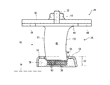
which is intended to extend radially in the flow from the guiding surface
and a securing portion which extends from the guiding surface radially
opposite the vane; remarkable in that the securing portion of the blade
comprises a lattice which is secured to the wall in order to fix the blade to
the wall via the lattice.
[0006] According to one embodiment of the disclosure, the lattice is a three-
dimensional lattice with interwoven rods which are joined to each other so
as to form meshes, the lattice comprising a plurality of meshes over the
thickness and/or the length of the vane and/or in the radial direction.
[0007] According to another embodiment of the disclosure, the at least one
blade
comprises a leading edge, a trailing edge, an intrados surface and an
extrados surface, the intrados surface and the extrados surface extending
from the leading edge to the trailing edge; and the lattice extending from
the leading edge to the trailing edge of the vane, and from the intrados
surface to the extrados surface.
CA 02897889 2015-07-20
3
[0008] According to another embodiment of the disclosure, the wall is an
internal
shroud or a segment of internal shroud, preferably the internal shroud
and/or the wall is produced from a composite material having an organic
matrix.
[0009] According to another embodiment of the disclosure, the wall comprises
at
least one opening in which the securing portion is arranged, preferably the
lattice extends radially beyond the opening, more preferably the lattice is
radially spaced apart from the opening.
[0010] According to another embodiment of the disclosure, the wall is integral
with and is formed by a material which fills the lattice.
[0011] According to another embodiment of the disclosure, the stator comprises
a
sealing joint which is placed against the wall radially opposite the guiding
surface, the lattice being at least partially secured in the radial thickness
of
the joint, optionally the joint comprises a matrix and balls which are in
contact with the lattice.
[0012] According to another embodiment of the disclosure, the joint comprises
a
layer of abradable material which is intended to cooperate by means of
abrasion with the rotor of the turbomachine, the lattice being at least
partially arranged in the radial thickness of the layer of abradable material,
optionally the layer of abradable material comprises a silicone material.
[0013] According to another embodiment of the disclosure, the lattice extends
over the majority of the axial length of the wall and/or the radial height of
the wall.
[0014] According to another embodiment of the disclosure, the vane comprises a
solid body which extends over the majority of the radial height thereof,
preferably at least over the entirety of the radial height thereof.
[0015] According to another embodiment of the disclosure, the lattice
comprises a
compactness which is less than 60%, preferably less than 30%, more
preferably less than 10%.
[0016] According to another embodiment of the disclosure, the securing portion
is
a first securing portion, and the lattice is a first lattice, the wall is a
first
wall, the at least one blade further comprising a second securing portion
with a second lattice which is radially opposite the first lattice relative to
the
CA 02897889 2015-07-20
4
vane and which is secured in a second wall which is concentric with the
first wall.
[0017] According to another embodiment of the disclosure, the blade comprises
a
fixing plafform, optionally with a fixing shaft, which is arranged radially
opposite the lattice relative to the vane; the stator preferably comprises an
external housing, the platform being fixed to the external housing.
[0018] According to another embodiment of the disclosure, the vane, the
lattice
and optionally the fixing platform are integral and are produced by means
of additive production, preferably based on titanium powder.
[0019] According to another embodiment of the disclosure, the guiding surface
is
radially at a height between the vane and the securing portion.
[0020] According to another embodiment of the disclosure, at least one or each
securing portion is connected to a vane.
[0021] According to another embodiment of the disclosure, the wall comprises
an
upstream axial half and a downstream axial half, preferably the lattice is
axially spaced apart from one of the axial halves, optionally spaced apart
from the upstream half.
[0022] According to another embodiment of the disclosure, the wall may be
annular or generally tubular, or form an angular ring portion or tube
portion.
[0023] According to another embodiment of the disclosure, the securing portion
comprises a network of channels which extends through the securing
portion and the lattice, optionally axially and/or laterally.
[0024] According to another embodiment of the disclosure, the lattice
comprises a
regular mesh; or the mesh is variable, optionally the mesh becomes more
dense in the direction radially away from the vane, or becomes more
dense in the region of the leading edge or trailing edge.
[0025] According to another embodiment of the disclosure, the lattice and the
wall
are produced from different materials.
[0026] According to another embodiment of the disclosure, the lattice is
filled with
a polymer material, such as an elastomer resin.
CA 02897889 2015-07-20
[0027] According to another embodiment of the disclosure, the lattice
comprises
at least one rod which extends over the majority, preferably the whole, of
the length or the width of the blade.
[0028] According to another embodiment of the disclosure, the lattice
comprises
at least two sets, preferably at least three sets of parallel rods, each set
comprising rods which are perpendicular to the rods of the other sets.
[0029] According to another embodiment of the disclosure, the lattice
comprises
at least four sets of parallel rods, each set comprising rods which are
orientated at 60 relative to the rods of the other sets.
[0030] According to another embodiment of the disclosure, the lattice extends
over the majority, preferably over the whole, of the axial length and/or the
thickness of the vane.
[0031] According to another embodiment of the disclosure, in the state not
secured to the shroud, the lattice is mostly empty, preferably 75% empty,
more preferably 90% empty.
[0032] The compactness of the lattice is understood to be the ratio between
the
volume which is occupied by the material which forms the lattice and the
total volume in which the lattice is arranged.
[0033] According to another embodiment of the disclosure, the lattice is less
long
axially than the opening or each opening.
[0034] According to another embodiment of the disclosure, the vane and each
securing portion form a radial stack.
[0035] The disclosure also relates to a turbomachine, comprising a stator,
remarkable in that the stator is in accordance with the disclosure,
optionally the wall comprises an upstream axial half and a downstream
axial half, preferably the lattice is axially spaced apart from one of the
axial
halves, optionally spaced apart from the upstream half.
[0036] The present disclosure enables the stability of the securing between a
blade and a wall to be improved. The disclosure increases and distributes
the contact surface between the securing portion and the wall; optionally
via the joint, so that the inclined and asymmetrical shrouds as on the first
rectifier and on the last rectifier are more stable. The lattice distributes
the
CA 02897889 2015-07-20
6
forces between the blade and the wall. The compactness thereof which is
lower than that of the vane reduces the mass of the stator.
[0037] The lattice forms a zone of reduced rigidity in the blade, it is more
flexible
and can absorb, damp an impact by limiting the energy transmitted to the
wall. The rods may be inclined relative to the radial direction in order to
promote the radial extension of the lattice and to further reduce the energy
transmitted in the case of a radial tearing force. In this manner, the
retention and the fixing become more reliable.
[0038] The use of a lattice is compatible with a moulding of a wall or a joint
on the
securing portions. This solution reduces the assembly costs for a specific
retention resistance.
Brief description of the drawings
[0039] Figure 1 shows an axial turbomachine according to the disclosure.
[0040] Figure 2 is a diagram of a turbomachine compressor according to the
disclosure.
[0041] Figure 3 is a cross-section of a turbomachine stator according to the
disclosure, when viewed in profile.
[0042] Figure 4 is a cross-section of a portion of a turbomachine stator
according
to the disclosure, when viewed axially.
Description of embodiments
[0043] In the following description, the terms inner or internal and outer or
external refer to a positioning relative to the rotation axis of an axial
turbomachine.
[0044] Figure 1 shows an axial turbomachine in a simplified manner. In this
particular instance, it is a dual-flow turboreactor. The turboreactor 2
comprises a first compression level, referred to as a low-pressure
compressor 4, a second compression level, referred to as a high-pressure
compressor 6, a combustion chamber 8 and one or more turbine levels 10.
During operation, the mechanical power of the turbine 10 transmitted via
the central shaft to the rotor 12 causes the two compressors 4 and 6 to
move. Step-down means may increase the rotation speed transmitted to
the compressors. Alternatively, the different turbine stages may each be
CA 02897889 2015-07-20
7
,
connected to the compressor stages via concentric shafts. They comprise
several rows of rotor blades which are associated with rows of stator
blades. The rotation of the rotor about the rotation axis 14 thereof thus
allows a flow of air to be generated and compressed progressively as far
as the inlet of the combustion chamber 8.
[0045] An inlet ventilator which is generally referred to as a fan or blower
16 is
coupled to the rotor 12 and generates a flow of air which is divided into a
primary flow 28 which passes through the different above-mentioned
levels of the turbomachine, and a secondary flow 20 which passes through
an annular conduit (partially illustrated) along the machine in order to then
join the primary flow at the outlet of the turbine. The secondary flow may
be accelerated in order to generate a reaction. The primary flow 18 and
secondary flow 20 are annular flows, they are channelled via the housing
of the turbomachine. To this end, the housing has cylindrical walls or
shrouds which may be internal and external.
[0046] Figure 2 is a sectioned view of a compressor of an axial turbomachine 2
such as that of Figure 1. The compressor may be a low-pressure
compressor 4. It is possible to observe therein a portion of the fan 16 and
the separation nose 22 of the primary flow 18 and the secondary flow 20.
The rotor 12 comprises a plurality of rows of rotor blades 24, in this
instance three.
[0047] The compressor 4 comprises a plurality of rectifiers, in this instance
four,
which each contain a row of stator blades 26. The rectifiers are associated
with the fan 16 or with a row of rotor blades 24 in order to rectify the flow
of
air, in order to convert the flow speed into pressure.
[0048] The compressor comprises a stator 28, optionally with an external
housing
30 which forms a partition which supports the separation nose 22. The
partition supports the rectifiers and annular layers of abradable materials
which are arranged between the rectifiers. The external housing 30 may
be circular or annular and/or be formed by half-shells. It may be produced
from composite material having an organic matrix. The stator blades 26
extend substantially radially from the partition of the outer housing 30, and
may be fixed at that location using a through-shaft 32.
CA 02897889 2015-07-20
8
[0049] The stator 28 comprises at least one wall 34, preferably a plurality of
walls,
such as internal shrouds 34 which are connected to the inner ends of the
stator blades 26 via securing portions. The wall 34 and the external
housing 30 are concentric. The securing portion of at least one stator
blade 26 comprises a lattice 36, preferably each blade of a row of stator
blades 26 comprises a securing portion with a lattice 36, more preferably
each stator blade 26 of at least one compressor 4 of the turbomachine
comprises a securing portion having a lattice 36. The or each lattice 36
may be secured or sealed to the wall 34 and/or to the inner shroud 34.
[0050] The stator 28 may comprise at least one joint 38 which is associated
with
the wall 34 or each wall 34. The or each lattice 36 may be engaged in the
joint 38 in order to be secured at that location and to form a fixing between
a stator blade 26 and the joint 38, and therefore between a stator blade 26
and the associated wall 34. The stator 28 illustrated is that of the
compressor, but the disclosure could be used equally well for a turbine
stator or for a stator of a turbomachine blower.
[0051] Figure 3 shows the stator 28. It is possible to see therein an internal
shroud which is connected to the external housing 30 via a stator blade
26, the lattice 36 of the blade is accommodated in the joint 38.
[0052] The blade or each blade 26 comprises a plurality of radial portions,
including a vane 40 which extends radially in the flow and at least one
securing portion 42. The blade 26 may optionally comprise a fixing
platform 44 which forms an assembly support. The platform 44 may be
fixed to the external housing 30 using the fixing shaft 32 thereof and a
lockbolt 46, or have holes which coincide with holes of the external
housing. It may be a plate which is rectangular or in the form of a
parallelogram, and may be bordered axially by annular layers 48 of
abradable material upstream and downstream. The platform 44 may be
pressed against the external housing 30 and/or may conform to the
external housing 30, optionally over the majority of the length thereof. The
blade comprises a leading edge 50 which is connected to the trailing edge
52 via the intrados surface and the extrados surface. The blade 26 may be
inwardly curved, cambered.
CA 02897889 2015-07-20
9
[0053] The wall 34 may be the internal shroud 34. The wall may comprise a
guiding surface 54 for guiding and delimiting a flow, such as the primary
flow 18 of the turbomachine. This surface is generally annular, optionally
substantially cylindrical, and may be segmented angularly. It extends over
the entire length of the vane 40, and may extend beyond in an upstream
and downstream direction
[0054] The wall 34 may comprise at least one opening 56 or a row of openings
56, each opening 56 receiving a securing portion 42 for a blade 26 in order
to fix it, in particular by means of securing. This fixing can be carried out
in
different manners, for example, with a rod. The space between the
opening 56 through which the blade 26 passes and the vane 40 may be
closed using a bead of silicone 58 in order to prevent leakages. The
securing portion 42 may comprise a smooth portion in order to cooperate
with the bead 58, the lattice being radially recessed relative to the bead 58
and/or the opening 56. The vane 40 may extend radially towards the outer
side from the wall 34, from an opening 56. Alternatively, the wall may
comprise pockets in which the latticees are secured.
[0055] The wall may have a web with a profile which is formed by means of
revolution about the rotation axis 14 in the form of an inverted "U", with an
axial portion, such as a sleeve, extended radially and delimited axially by
radial portions. The web may delimit an internal annular space. The wall
34 may be metal or of composite material with an organic matrix in order
to reduce the mass whilst optimising the rigidity. The wall 34 may be
circular or form a circular arc. It may be a shroud segment, that is to say,
be in the form of an angular sector of a circle. In this instance, a stator
forms a circle as a result of a plurality of segments which are placed end-
to-end.
[0056] The stator 28 may comprise an annular or semi-annular sealing joint 38
which is arranged against the wall 34, opposite the vane 40 relative to the
guiding surface 54. This joint 38 may be placed in the annular space of the
web of the wall 34, and may fill this space. It may surround the ends of
blades 26 or vanes 40, and may be introduced in the or each securing
portion 42. The joint 38 may be an elastomer material which forms a
CA 02897889 2015-07-20
matrix, such as silicone. It may be an annular layer of abradable material
which is capable of crumbling in the case of contact with the rotor. It may
comprise a matrix and particles, such as balls, in order to promote the
brittle nature of the joint. These balls may cooperate with the lattice and be
configured to improve the securing.
[0057] The or each lattice 36 may form the internal end, the tip of the blade
26.
The or each lattice 36 may comprise rods 60 which are connected to each
other. They may be straight or curved. They may be connected to each
other at the intersections thereof. The rods 60 may form at the
intersections thereof nodes which are optionally integrated in their cross-
sections. The lattice may be integral.
[0058] The or each lattice 36 may be planar, and/or formed over a skewed
surface, for example, parallel with the radial extension of the intrados
surface or the extrados surface. It may be substantially bi-directional, for
example, having flat meshes which are formed by the rods 60 thereof. The
or each lattice may be three-dimensional and have polyhedral meshes
whose edges are formed by the rods 60. The meshes may be
tetrahedrons and/or cubes. The rods 60 thereof may be arranged in
accordance with at least three directions, for example, perpendicular to
each other. The rods 60 may form sets of rods 60 which have the same
directions, and/or the same curvatures.
[0059] The or each lattice 36 may extend in the radial extension of the vane
40. It
may extend between the leading edge 50 and the trailing edge 52,
optionally it extends beyond these edges. It may extend over the majority,
preferably over the whole of the chord of the vane 40 in the region of the
guiding surface 54. The or each lattice 36 may form a plurality of meshes
over the vane 40, preferably at least ten meshes, more preferably at least
fifty meshes. The or each lattice 36 may extend over the majority of the
axial length of the wall 34. The axial extension of the lattice 36 allows the
tilting of the wall 34 relative to the blade 26 to be limited, which may occur
when the wall is short over the circumference. At least one rod 60 or a set
of rods 60 may extend over the majority, optionally over the axial entirety
of the vane 40, and/or the securing portion 42.
CA 02897889 2015-07-20
11
[0060] The or each lattice 36 may have a variable heterogeneous mesh. The
meshes may become tighter towards the vane 40, and optionally in the
region of the leading edge 50 and the trailing edge 52, for example, in
order to increase the forces which the rods 60 of the lattice 36 can transmit
in the event of intake. The rods 60 may increase in number and/or become
more fine towards the inner side. The compactness of each lattice 36 is
less than 90%, preferably less than 50%, more preferably less than 5%.
The compactness may double from one end to the other. It may vary by
10%, preferably by 30%. Alternatively, the mesh may be constant,
homogeneous, optionally locally.
[0061] The or each lattice 36 may be secured in the joint 38 and/or in the
very
material which forms the wall 34 and the guiding surface 54. The lattice 36
is embedded in the material of the joint 38, the rods 60 merge at the joint
38.The joint 38 is introduced in and occupies the meshes of the lattice in
order to fill them. In this manner, the joint 38 completely fills the space
that
the lattice, via the rods thereof, does not occupy. All these properties of
the joint can be transposed to the material of the wall. The joint 38 may be
moulded on the wall, or even projected. The lattice 36 may extend over the
majority of the thickness of the profile of the joint 36 as formed by means
of revolution. This securing depth in the joint improves the retention and
the sealing effect.
[0062] Figure 4 shows a portion of the stator 28 of the turbomachine. A row of
stator blades 26 which fix a wall 34 to another wall 30 via latticees 36
which are fixedly joined to the joint 38 is shown.
[0063] The row of blades may be an annular or semi-annular row; that is to
say,
which describes an angular sector of a circle. The platforms 44 may be in
contact with each other as a result of the lateral edges thereof in order to
position the blades 26, and therefore the wall 34. At least one or each
lattice 36 may extend radially in the extension of the thickness of the vane
40, the thickness being able to be understood in accordance with the
circumference. At least one or each lattice 36 may extend the
aerodynamic profile of the vane 40 in the region of the guiding surface 54,
optionally reproducing the cambered appearance of the profile.
CA 02897889 2015-07-20
12
[0064] At least one or each lattice 36 may form a plurality of meshes over the
thickness of the vane 40, for example, at least two, preferably at least five,
more preferably at least ten meshes. At least one or each lattice 36 may
have, radially in the region of the maximum thickness thereof, a plurality of
rods which extend mainly axially. The lattice 36 may be wider than the
vane 40 and less wide than the associated opening 56.
[0065] The height of at least one or each lattice 36 may be greater than the
maximum thickness of the vane 40, preferably at least three times greater.
At least one or each lattice 36 may be radially spaced apart from the
associated opening 56, and/or the internal surface of the joint 38. At least
one or each lattice 36 may have a general envelope whose surfaces are
inclined relative to the intrados surface 62 and the extrados surface 64 of
the associated blade in the region of the guiding surface 54.
[0066] The presence of fixing platforms 44 is entirely optional, since each
blade
may comprise two latticees in order to be secured to two walls. At least
one or each blade 26 of the row may comprise a first internal securing
portion which is secured by means of the first lattice thereof to the internal
shroud 34, and a second external securing portion which is secured by
means of a second lattice to the external housing 30. The latticees are
separated by the vane, each of them may be secured in the thickness of
the web of the external housing, in particular when it is moulded.
[0067] At least one or each blade 26, in particular the vane 40 thereof, the
lattice
36 thereof and optionally the platform 44 thereof; or the vane thereof and
the latticees thereof are integral and may be produced by means of
additive production. They can be produced based on titanium powder or
polymer in order to form an integral assembly. The blade may form an
integral element with a mixed structure, having a vane which is solid and a
lattice which is partially empty.
[0068] The blade may be produced in the form of a row of blades, with at least
one or more blades having a securing lattice, and optionally other means
for fixing at the same radial side as the latticees on other blades. In this
alternative embodiment, the row of blades may have a common platform
having a plurality of vanes.