Note : Les descriptions sont présentées dans la langue officielle dans laquelle elles ont été soumises.
CA 02898157 2015-07-14
W02014/127996
PCT/EP2014/052262
Housing with a Rotational Friction Welding Seam
The object of the invention is a housing, in particular
for electrical operating means, said housing comprising a
rotational friction welding seam, and a method for
manufacturing such a housing.
In order to produce tubular housings, in particular
pressure-resistant housings, drawbar structures for end-side
closure or closures with casting compounds are frequently
used, their assembly requiring special mechanical preparation.
Publication EP 1 255 072 A2, for example, shows an explosion-
proof lamp with a translucent housing tube whose housing parts
are connected to each other with the use of two tie anchors.
However, the manufacture and assembly of such structures is
expensive.
Furthermore, the method of rotational friction welding
has been known for connecting thermoplastic plastic materials.
In this case, the required thermal energy is applied for
fusing the materials by relative rotation of the parts to be
connected. Inasmuch as a friction welding process takes a
maximum of a few seconds, it is possible to produce objects at
a high clock rate in this manner.
Publication DE 38 53 951 T2 describes a plastic container
that is pressure-proof and comprises a tubular body part and
end closure parts, in which case an annular recess is provided
on the edge of one end closure part. The end of the tubular
body part is placed in the recess. Subsequently, the end
closure part as well as the tubular body part are connected to
each other by fusing the end of the tubular body part to the
former by means of rotational friction welding. This is aided
- 1 -
CA 02898157 2015-07-14
WO 2014/127996
PCT/EP2014/052262
by an undercut which is provided on the recess and into which
the fusing material of the end will flow. As a result, the
housing is closed in a fluid-tight manner and disposed for
receiving fluids that are under static pressure, wherein, for
example, pressures of approximately 10 bar may act on the
container body.
Publication DE 199 11 284 Al describes a method for
producing a sleeve joint of two tubes. The sleeve that tapers
slightly conically toward the center is subjected to a
rotational movement. The non-rotationally supported tubes are
moved along the axis of rotation of the sleeve into said
sleeve so that a fusion of the sleeve and pipe material and
the formation of a rotational friction welding seam are
attained. The sleeve and the tubes display comparable radial
elasticity. This is different in the case of the connection of
a relatively rigid cap or a lid for a housing having a
cylindrical base body that is relatively elastic with respect
thereto. Under conditions of alternating thermal stress there
is the risk of a crack formation, in particular at the axial
transition of the cap to the tube. In addition, in case of an
explosion inside or outside the housing, i.e., under shock-
like pressure stress, it is possible for the base body to
shear off in particular at such a transition from a cap or a
sleeve to the tube.
It is the object of the invention to provide an improved
housing, in particular for electrical operating means, and a
method for the manufacture such a housing.
In accordance with the invention, this object is achieved
with a housing displaying the features of Claim 2, as well as
with a method according to Claim 15.
In particular, the housing is disposed for the
accommodation of electrical operating means; however, it may
also act as the housing for other devices. The housing
- 2 -
CA 02898157 2015-07-14
WO 2014/127996
PCT/EP2014/052262
comprises a first part with a first wall that has, e.g., a
cylindrical outside wall surface. A second part of the housing
with a second wall has an inner wall surface that may be
cylindrical, for example. The first wall and the second wall
overlap in an overlap region and are connected within the
overlap region by means of a rotational friction welding seam
on the wall surfaces along their circumference. The rotational
friction welding seam forms a circular closed ring. The
rotational friction welding seam is defined concentrically to
the center axis of the housing, said axis forming - at the
same time - the axis of rotation of the housing.
The rotational friction welding seam comprises at least
one compact zone and one mixing zone. The compact zone
preferably exhibits a homogenous material distribution. The
mixing zone preferably exhibits an inhomogeneous material
distribution. For example, the compact zone may be produced by
fully fused material. The mixing zone may contain partially
fused material. The rotational friction welding seam may
comprise one single or several mixing zones or one single or
several compact zones. Due to the compact zone and the mixing
zones, it is possible to create zones exhibiting different
elasticities. In so doing, in particular the mixing zone can
act as the radial transition zone between a first part and a
second part exhibiting different elasticities - in particular
in a direction transverse to the axis of rotation. A mixing
zone may contain, for example, pores, other interstices,
abrasion solids and/or solids fragments and/or slubs and/or
lamellae of re-solidified melt. The mixing zone displays
mechanical properties that are different from the mechanical
properties of the compact zone. In particular, the mixing zone
may exhibit a higher resilience than the compact zone, i.e.,
may offer less resistance during deformation.
Preferably, the mixing zone is arranged on one axial end
of the rotational friction welding seam. Respectively one
mixing zone may be formed on each of the two axial ends, said
- 3 -
CA 02898157 2015-07-14
WO 2014/127996
PCT/EP2014/052262
= mixing zone being axially separated by a compact zone.
Preferably, a mixing zone is arranged in one axial edge region
of the overlap region, i.e., along the axis of rotation, where
the transition from the overlap region to the first part or to
the second part is located. For example, the compact zone may
be arranged axially in the center of the rotational friction
welding seam. It is also possible for the compact zone to
extend from a region in the axial center of the rotational
friction welding seam to one axial end of the rotational
friction welding seam.
A uniform or abrupt transition may be created between the
compact zone and the mixing zone parallel to the axis of
rotation. The transition between the compact zone and the
mixing zone may follow a straight line along the circumference
or be curved or have a wave-form, i.e., the compact zone may
enter into the mixing zone, for example, parallel to the axis
of rotation. Parallel to the axis of rotation, the compact
zone may have a greater extension (length) than the mixing
zone.
Compact zones and mixing zones may alternate along the
circumference of the rotational friction welding seam, and
each may extend, for example, parallel to the axis of
rotation. One or more mixing zones may be formed as spots or
islands in a compact zone, in which case the compact zone may
be cohesive, for example. It is also possible for one or more
compact zones to be configured as spots or islands in a mixing
zone, in which case the mixing zone may be cohesive, for
example. Spots of compact zones and mixing zones,
respectively, may be arranged regularly or form an irregular
pattern. Accordingly, compact zone spots and mixing zone spots
may be arranged alternately in circumferential direction
and/or in the direction of the axis of rotation.
The fused or re-solidified material in the compact zone
preferably exhibits greater density than the material of the
- 4 -
CA 02898157 2015-07-14
WO 2014/127996
PCT/EP2014/052262
mixing zone. For example, it may contain fewer pores, abrasion
solids or the like. The compact zone is disposed to achieve
the integrity of the housing, in particular in the event of
forces acting parallel to the axis of rotation. Due to the
compact zone, it is possible to achieve in particular the leak
tightness of the housing. The mixing zone is disposed, in
particular, to mechanically secure the transition from the
first to the second part and may act as a buffer zone. Due to
the inhomogeneity of the mixing zone, the mixing zone may be
turbid or even opaque, even if a glass-clear plastic material
is used.
Preferably, the rotational friction welding seam extends
axially along the entire overlap region. The rotational
friction welding seam extends parallel to the axis of rotation
and is preferably restricted to the overlap region. However,
the rotational friction welding seam may also extend - at
least on one side - beyond the overlap region. For example,
the solidified melt may also be provided outside the overlap
region and contribute there, for example, to the mechanical
stability and/or the leak tightness of the frictional welding
seam. Preferably, the first part and the second part are
connected to each other without interruption on the wall
surfaces along the entire periphery, i.e., along the
circumference.
The (axial) lengths of the compact zone and the mixing
zone may be different and, for example, are a function of the
material and form parameters of the first and the second part
and, in addition, of the parameters of the manufacturing
process. The length of the mixing zone may be a few
millimeters, for example. However, the length of the mixing
zone may also be only a few hundredths of a millimeter. The
compact zone is preferably longer than the mixing zone. The
length of the compact zone is at least 10 mm, for example. The
thickness of the compact zone and the thickness of the mixing
zone of a rotational friction welding seam may differ in
- 5 -
CA 02898157 2015-07-14
WO 2014/127996
PCT/EP2014/052262
radial direction transverse to the axis of rotation. The
mixing zone may be radially thicker than the compact zone.
This promotes its springy and/or plastic deformability or
resilience.
In addition to the first and second parts, the housing
may comprise additional parts. Connections between the parts
of the housing may be rotational friction welding seams, or
the parts may be connected in another manner. The housing or a
part of the housing may be transparent or translucent.
Preferably, the housing is waterproof. It is advantageous if
the housing is configured so as to satisfy the specifications
of protection level explosion-proof encapsulation (Ex-d).
Particularly preferably, the housing (in particular the
connections of housing parts) satisfies the specifications of
DIN EN 60079-1. The housing may also be configured to satisfy
protection level Ex-e. For example, the housing may act as a
lamp housing or as a housing for signal transmitters or be
used for the shielded installation of cables, for example, as
cable conduits, or contain optical sensors.
Preferably, the housing has a cylindrical, tubular body.
Furthermore, the housing may have a cap that is designed to
close the tubular body on one side. To do so, the cap is
placed over the tubular body and forms an overlap region
together with said tubular body. In this manner, the overlap
region between the first part (e.g., the tubular body) and the
second part (e.g., the cap) is formed. The overlap region of
the tubular body with the cap may comprise a rotational
friction welding seam having a compact zone and a mixing zone.
A housing may also have a tubular body in that at least a
stopper is provided on one side of the body, said stopper
closing said body. For example, in the case of such a housing,
the first part is the stopper and the second part is the
tubular body. The stopper and the body, in turn, may be
connected by the previously described rotational friction
welding seam.
- 6 -
CA 02898157 2015-07-14
WO 2014/127996
PCT/EP2014/052262
The housing may comprise at least one tubular part that
is connected to a sleeve or a nipple by means of an inventive
rotational friction welding seam having a compact zone and a
mixing zone. It is also possible to directly connect two
tubular parts with the aid of a sleeve, a nipple or by direct
connection by means of rotational friction welding seams. A
sleeve is viewed as a cuff-like connecting piece that is
arranged around the end sections of both tubular parts in
order to connect said parts. A nipple is a connecting piece
that is arranged inside the tubular parts in the end sections
of both tubular parts.
Each of the first and second parts has a wall that has a
wall surface extending inside or outside around the wall. Such
a wall surface may be smooth and round or have corners so as
to form a multi-edge surface, or have facets. In cross-
section, i.e., in a direction transverse to the axis of
rotation, the wall surface may be circular or elliptical or
polygonal. A part of the wall surface may have a tubular form,
for example, in which case it may be a cylindrically round or
multi-edge tubular form or a prismatic tubular form. The wall
surface may extend parallel to the axis of rotation and have a
constant diameter or circumference along the axis of rotation.
The wall surfaces have the "shape of a casing". This includes
wall surfaces having a straight cylindrical casing shape, for
example also conical wall surfaces or curved wall surfaces
that enclose a body. A wall surface, for example, may be round
or wave-shaped so as to at least partially deviate from a
straight conical or cylindrical wall form. For example, the
casing-shaped wall surface may also conically widen or taper -
at least in some sections - in the direction of the axis of
rotation. Furthermore, a casing-shaped wall surface may
include a step, i.e., an abruptly changing diameter. One or
more slits or gaps may exist in a casing-shaped wall surface,
for example in axial direction. In this manner, the wall
surface may be interrupted along its circumference. The shapes
- 7 -
CA 02898157 2015-07-14
WO 2014/127996
PCT/EP2014/052262
of the wall surfaces of the first and of the second wall are
configured so as to be complementary relative to each other.
Preferably, a form deviating from the conical form or from a
strict, cylindrical form may be characterized at least in some
sections by an angle that defines the inclined position of the
wall surface relative to and in the direction toward the axis
of rotation. Preferably, the angle characterizing the inclined
position is between 1 degree to 3 degrees.
The wall surfaces of the first and/or the second parts
may have recesses such as, for example, pockets, scores or
grooves. For example, such recesses may act to receive the
melt or conduct or guide the melt flow, or to control the
formation of the melt during the production of the friction
welding seam. Preferably, recesses are arranged in and
restricted to the overlap region. Sections of a recess may
extend over the overlap region or project over said region on
at least one side of the overlap region. Recesses may extend
along and/or transversely to the axis of rotation. Recesses,
in particular grooves or furrows, may extend along the
circumferential direction of a casing-shaped wall surface. In
this manner, a recess may follow a helical line on the wall
surface. A recess may extend along the axis of rotation.
Preferably, a part has several grooves extending in
circumferential direction. One wall surface of a part, for
example the first part, may have recesses, whereas the wall
surface of the other part does not have any recesses. The
first and the second parts may have channels for controlling
the formation of the melt or the melt flow, for example.
In one embodiment, neither the first nor the second wall
surfaces have recesses in the overlap region, in which case
the surface roughness is excluded. In this manner, the
rotational friction welding seam can be formed without
undercuts.
- 8 -
CA 02898157 2015-07-14
WO 2014/127996
PCT/EP2014/052262
=
The diameter of a first or of a second part may be 10 mm
to 70 mm, relative to the wall surface. The thickness of the
wall of one part preferably depends on the diameter of the
part and may be 1 mm to 5 mm, for example.
A wall and its wall surface may consist of the same
material or of different materials. The walls of the first and
of the second parts may consist of the same or different
materials or partially consist of a different material.
Preferably, the first wall and the second wall consist of or
contain plastic material. The preferred wall material is an
amorphous thermoplastic plastic material. For example, one
wall may consist of polycarbonate. It is also possible, for
example, that - of the first and the second parts - only the
wall of one part consists of or contains plastic material,
whereas the other wall consists of glass, metal or a composite
material, for example.
The homogeneous compact zone and/or the inhomogeneous
mixing zone of the frictional welding seam may each contain a
single type of plastic material such as, for example,
polycarbonate, or contain or consist of several types of
plastic material. In particular, the compact zone, as well as
the mixing zone, may contain or be mixed with materials of the
first wall and of the second wall.
Preferably, each of the first and the second parts has an
end surface. An end surface may be oriented transversely
relative to a wall surface. For example, in one embodiment
with a cap and a cylindrical tube on one side, an end surface
is created by an axial cover surface at one end of the tube;
on the other side, the cap has an end surface that axially
closes the tube. In addition to the connection by the
rotational friction welding seam, the first and the second
parts may be connected by an axial rotational friction welding
seam on the end surfaces of the first and the second parts.
For example, a ring may be arranged in a sleeve, said ring
- 9 -
CA 02898157 2015-07-14
WO 2014/127996
PCT/EP2014/052262
having two end surfaces, wherein a tube arranged in the sleeve
may be connected to the sleeve by means of a rotational
friction welding seem on the circumference and an axial
rotational friction welding seam on one end surface.
In one embodiment the first and the second parts may not
have any friction welding seam on an end surface separate from
a wall surface and thus be connected by a friction welding
seam only on the circumference on the casing-shaped inner and
outer wall surfaces, respectively.
The method in accordance with the invention relates to
the formation of a friction welding seam having a compact zone
and a mixing zone. The method is designed for the manufacture
of a housing that can be used for electrical operating means
and that defines an axis of rotation and comprises a first
part with a first wall and a second part with a second wall.
The first wall has a casing-shaped outer wall surface and the
second wall has a casing-shaped inner wall surface. To produce
this, the first part and the second part are rotationally
driven relative to each other about the axis of rotation. The
first part and the second part can be moved toward each other
by a relative feed movement. In the event of a contact of the
end surfaces and/or the circumferential surfaces of the first
and the second parts, a fusion of the material of at least one
part of the contact surface occurs. Finally, due to the re-
solidified melt, a friction welding seam is formed on the wall
surfaces, said friction welding seam comprising a compact zone
having a homogeneous material distribution and a mixing zone
having an inhomogeneous material distribution. The formation
of the compact zone and of the mixing zone and their
properties such as, for example, the length of the zones in
the direction of the axis of rotation, may be controlled by
material parameters, form parameters and process parameters.
In conjunction with this, for example, the diameters of the
first part and of the second part play a role as the form
parameters, wherein, preferably, an interference fit between
- 10
CA 02898157 2015-07-14
WO 2014/127996
PCT/EP2014/052262
the first and the second parts is selected. Preferably, one
part has a section that tapers conically in feed direction,
followed by a section having a constant circumference along
the axis of rotation. In this manner, it is possible to form a
stop slope on the part. The other part may comprise a
clearance fit relative to the conically tapering section and
an interference fit on the section having the constant
circumference. The properties of the compact zone and the
mixing zone, for example their lengths, their configuration
and the like, can also be controlled via the lengths of the
conical section, the angle of the conical section and the
length of the section having the constant circumference, as
well as via the interference of the interference fit.
In order to control the formation of the compact and the
mixing zones, additional recesses such as, for example,
grooves may be provided in the first and/or in the second
parts, said grooves being able to at least partially receive
and/or transport the forming melt. The recesses may also be
circular or rectangular or square, for example. Furthermore,
elevations such as, for example, nubs or elongated elevations
may be provided on the first and/or the second parts.
Parameters that influence compact and mixing zones are, for
example, the dimensions of the recesses or elevations, the
orientation relative to the axis of rotation, the progression
relative to the direction of rotation, and the arrangement in
the region of the rotational friction welding seam. Other
control options result from the relative speed of the surfaces
of the first and second parts, the feed speed, the feed force
and also from the chronological progression of said values via
the friction welding process, as well as the entire process
time from the fusion of the wall material up to the
solidification of the melt. In guiding the process, the fusion
is preferably restricted to only the wall surface regions of
the first and the second parts in order to attain the
stability of the first and second parts. This can be achieved,
e.g., by a relatively short process time.
- 11 -
,
CA 02898157 2015-07-14
W02014/127996
PCT/EP2014/052262
Advantageous embodiments of the invention can be inferred
from the dependent patent claims and the description.
Advantageous developments are obtained by the combination of
at least one of the independent claims with the features of
one or more dependent claims. The drawing supplements the
description. Features of the figures can be advantageously
combined with each other. The drawings show schematically in
Figure 1 a housing according to the invention with an
electrical operating means;
Figure 2 a section with a part of the overlap region of
the housing of Figure 1;
Figure 3 another embodiment of the housing according to
the invention;
Figure 4 a representation of the method according to
the invention with the use of a device for the manufacture.
- 12 -
,
CA 02898157 2015-07-14
WO 2014/127996
PCT/EP2014/052262
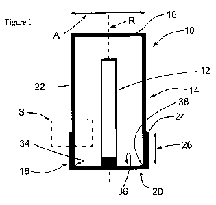
The housing 10 according to the invention shown in Figure
1 contains a lamp 12 and is configured in an explosion-proof
manner satisfying the safety level of a pressure-proof
encapsulation (Ex-d) and, additionally, is waterproof. By its
cylindrical shape, the housing 10 defines an axis of rotation
R. The housing 10 comprises a first part 14 that is tubular or
cylindrical and has a bottom 16. The first part 14 has an
outside diameter A of approximately 60 mm. A second part 18
having the form of a cap is welded onto the first part 14. The
first part 14 and the second part 18 are each produced by
injection molding and consist of an amorphous transparent
polycarbonate. However, the first part 14 and the second part
18 may also consist of different materials. For example, one
of the parts may consist of glass or steel or of a plastic
material other than polycarbonate.
The cap 18 comprises an end surface 20 that is oriented
transversely to the axis to rotation R. One section of the
first wall 22 of the first part 14 overlaps with a second wall
24 of the cap 18, said second wall extending around the first
part 14. The first wall 22 has an outer wall surface 28 that
has the shape of a cylindrical casing. It is connected to an
inner wall surface 30 of the second part 18 that has the shape
of a cylindrical casing via a rotational friction welding seam
32. The outer wall surface 28 and/or the inner wall surface 30
may also have a casing shape deviating from a cylindrical
form. For example, the wall surfaces may taper conically
and/or be provided with facets, and be configured as multi-
edge surfaces. On the end of the first wall 22 of the first
part 14 arranged in the second part 18, the first part 14 has
an annular end surface 34. Between the annular end surface 34
extending in circumferential direction and the end surface 36
of the end wall 20 of the second part 18, there is a welding
zone 38 with solidified melt. The solidified melt in the
welding zone 38 has formed due to friction of the cover
surface 34 on the end wall surface 36. The melt may also be
fused material of the outer wall surface 28 or the inner wall
- 13 -
,
CA 02898157 2015-07-14
WO 2014/127996
PCT/EP2014/052262
surface 30, which material has arrived by capillary action or
by material advance in the region of the welding zone 38 and
forms a heat bond at that location.
Figure 2 shows a detail S of the housing. The second wall
24 of the second part 18 has, in a first section 40 remote
from the end wall 20, a form that conically tapers in the
direction of the end wall 20. In a second section 42 located
closer to the end wall 20 along the axis of rotation R, the
inner wall surface of the second wall 24 has a constant
diameter. In an edge region 46 of the overlap region 26 at the
of the overlap region to the first part 14 along the axis of
rotation R, the rotational friction welding seam 32 has a
mixing zone 44 with an inhomogeneous material distribution. In
the exemplary embodiment, the mixing zone 44 is, in
particular, a fine-pore foam. This foam provides mechanical
securing in this edge region 46. In this manner, it is
possible, for example, to create a buffer zone that yields in
particular to forces that could be due to an explosion inside
the housing 10. Otherwise such forces could lead to a shearing
off of the first part 14 over the edge of the second part 18
in the edge region 46.
Furthermore, the rotational friction welding seam 32 has
a compact zone 48 that is located in a section of the
rotational friction welding seam 32 along the axis of rotation
R closer to the end wall 20. The rotational friction welding
seam may also have an additional melting zone that is
separated in axial direction, by the compact zone 48, from the
mixing zone 44. Compared with the mixing zone 44, the compact
zone 48 has a more homogeneous material distribution with a
greater density. The rotational friction welding seam 32 has a
radial thickness d that, due to the conical progression in
some sections of the otherwise conical progression of the
inner wall surface 30 having the shape of a cylindrical
casing, can assume different values along the axis of rotation
R. In addition, the depicted housing 10 has grooves 50 that
- 14 -
1
CA 02898157 2015-07-14
WO 2014/127996
PCT/EP2014/052262
are provided in the second wall 24 and extend around the
periphery of said wall. The grooves 50 are disposed to receive
the melt for the control of the melt flow and as undercuts for
mechanically securing the housing. The first wall 22 and the
second wall 24 are connected along their entire circumference
by means of the rotational friction welding seam. The recesses
or grooves 50 may also be configured as pockets that are
regularly or irregularly arranged at some points along the
circumference and that, for example, are disposed for
receiving excess melt or for mechanical securing.
Figure 3 shows another housing 10 according to the
invention, said housing containing an electrical operating
means 12. The first part 14 is configured as a massive stopper
that closes the second part 18. At the same time, the
electrical operating means 12 is fastened to the stopper. The
first part 14 has a first wall 22 that has an outer wall
surface 38 having the shape of a cylindrical casing. The first
part 14 and the second part 18 are connected only by a
rotational friction welding seam 32 between the outer surfaces
28 having the shape of a cylindrical casing and the inner wall
surface 30 of the second part 18 having the shape of a
cylindrical casing.
The rotational friction welding seam 32 has a mixing zone
44 that is provided at the transition from the first part 14
to the overlap region along the direction of the axis of
rotation in an edge region 46 of the overlap region 26. The
elastic modulus of the mixing zone 44 is greater than that of
the compact zone 48 that is provided next to the mixing zone
44 at a distance from the edge region 46. At this location,
the mixing zone 44 reduces the risk of a tearing off of the
second wall 24 during an explosion in the interior of the
housing 10. The compact zone 48 of the rotational friction
welding seam 32 has a homogeneous material distribution and is
disposed to seal the housing 10. There are no recesses
- 15 -
,
CA 02898157 2015-07-14
W02014/127996
PCT/EP2014/052262
= provided in the overlap region 26, so that the rotational
friction welding seam is formed without undercuts.
Figure 4 illustrates the method of the invention with the
use of a device 52 for the manufacture of a housing with a
friction welding seam.
The device for the manufacture 52 shown by Figure 4
comprises a first holder 54 into which a first part 14 of
polycarbonate is clamped so as to be non-rotational relative
to the first holder 54. A shaft 56 is arranged on the first
holder 54, whereby said shaft can drive the holder by means of
a rotational drive to rotate about an axis of rotation R. In
addition, the first holder 54 can be moved along an infeed
axis Z toward a second holder 58 of the device 52 or away
therefrom in a translatory manner.
A second part 18 of polycarbonate having the shape of a
cylindrical cap is clamped into the second holder 58 of the
device. The second holder 58 comprises a swivel bearing 60
that can be locked against rotation. The second part 18 has a
second wall 24 whose jacket-shaped inner wall surface 30 has
initially the shape of a cylindrical casing and widens
conically toward an end 62 of the second wall 24 remote from
the end wall 20. Other than that, the second wall 24 has the
shape of a cylindrical casing and is straight. The second
inner wall surface 30 of the second wall 24 having the shape
of a cylindrical casing has a first inside diameter I1 in the
straight region of the second wall 24 having the shape of a
cylindrical casing. In the conically tapering end 62, the
second wall 24 has a second inside diameter 12, wherein the
second inside diameter 12 is greater than the first inside
diameter I1 in the straight region having the shape of a
cylindrical casing due to the conically inclined wall surface
at the end 62. Due to a second inside diameter 12 that is
greater than the outside diameter A of the first part and a
conically tapering form of the second part, it is possible to
- 16 -
i
CA 02898157 2015-07-14
WO 2014/127996
PCT/EP2014/052262
create a stop slope at an angle a. Preferably, the angle a is
at most 3 degrees. For example, a lamp whose receptacle is
indicated in Figure 4 may be arranged in the second part 18.
The first part 14 and the second part 18 are preferably
arranged so as to be concentric relative to each other.
Between the longitudinal axes of the first part L1 and of the
second part L2 that coincide with the axis of rotation R in
the exemplary embodiment, there may also exist a parallel axis
offset, or the longitudinal axes L1 and L2 may extend in non-
parallel direction relative to each other. The first part 14
has a first wall 22 with an outer wall surface 28 having the
shape of a cylindrical casing, said outer wall surface 28
having an outside diameter A. The outside diameter A is
preferably greater than the first inside diameter Il, i.e.,
the first part represents an interference fit relative to the
second part.
The method for the manufacture of the housing 10 may be
performed, for example, with a device for the manufacture 52
as shown by Figure 4 as described hereinafter:
The swivel bearing 60 is blocked against rotation, and
the first part is rotated at a specific speed of rotation via
the first holder 54, via the shaft 56 and via the driving
motor. The first part 14 is moved along an infeed axis Z, said
axis extending parallel to the axis of rotation R in the
exemplary embodiment, back toward the second part 18 at a
specific feed speed. The feed and rotation speeds can be kept
constant or be varied during the friction welding process.
Starting at a certain relative distance between the first part
14 and the second part 18, the first wall 22 and the second
wall 24 come into contact with each other and frictional
forces lead to a fusing of the material of the inner wall
surface 30 and the outer wall surface 28. The feed movement is
performed until the desired distance of the bottom 16 from the
end wall 20 is reached. Then, the rotational movement of the
- 17 -
,
CA 02898157 2015-07-14
W02014/127996
PCT/EP2014/052262
first holder 54 is decelerated; in doing so, the blocking of
the swivel bearing 60 counter the rotation can be eliminated,
so that the second holder 58 also rotates, whereas the
rotation overall comes to a stop.
The invention relates to a housing 10 which has a first
part 14 with a first wall 22 and with an outer wall surface 28
and a second part 18 with a second wall 24 and with an inner
wall surface 30. The wall surfaces can have, for example, a
cylindrical casing shape at least in some sections. Portions
of the first wall 22 and the second wall 24 overlap in an
overlap region 26. The first wall 22 and the second wall 24
are connected along the circumference of the wall surfaces 28,
30 by means of a rotational friction welding seam 32 arranged
in the overlap region 26. The rotational friction welding seam
32 has a compact zone 48 with a first elastic modulus and a
mixing zone 44 with a different, second elastic modulus.
- 18
CA 02898157 2015-07-14
WO 2014/127996
PCT/EP2014/052262
List of Reference Signs
Housing
12 Electrical operating means / lamp
14 First part
16 Bottom
18 Second part
End wall
22 First wall
24 Second wall
26 Overlap region
28 Outer wall surface
Inner wall surface
32 Rotational friction welding seam
34 Peripheral end surface
36 End surface of the end wall
38 Welding zone
First section
42 Second section
44 Mixing zone
46 Axial edge region
48 Compact zone
Recess / groove / pocket
52 Device for the manufacture
54 First holder
56 Shaft
58 Second holder
Swivel bearing
62 End
A Outside diameter
Radial thickness
Ii First inside diameter
12 Second inside diameter
Li Longitudinal axis of the first part
L2 Longitudinal axis of the second part
Axis of rotation
Detail
- 19 -
CA 02898157 2015-07-14
WO 2014/127996
PCT/EP2014/052262
Infeed axis
a Angle
- 20 -