Sélection de la langue

Search

Sommaire du brevet 2898944 

Énoncé de désistement de responsabilité concernant l'information provenant de tiers

Une partie des informations de ce site Web a été fournie par des sources externes. Le gouvernement du Canada n'assume aucune responsabilité concernant la précision, l'actualité ou la fiabilité des informations fournies par les sources externes. Les utilisateurs qui désirent employer cette information devraient consulter directement la source des informations. Le contenu fourni par les sources externes n'est pas assujetti aux exigences sur les langues officielles, la protection des renseignements personnels et l'accessibilité.

Disponibilité de l'Abrégé et des Revendications

L'apparition de différences dans le texte et l'image des Revendications et de l'Abrégé dépend du moment auquel le document est publié. Les textes des Revendications et de l'Abrégé sont affichés :

  • lorsque la demande peut être examinée par le public;
  • lorsque le brevet est émis (délivrance).
(12) Brevet: (11) CA 2898944
(54) Titre français: STRUCTURE DE ROTOR A AIMANTS PERMANENTS
(54) Titre anglais: PERMANENT MAGNETIC ROTOR STRUCTURE
Statut: Accordé et délivré
Données bibliographiques
(51) Classification internationale des brevets (CIB):
(72) Inventeurs :
  • PAN, MINGPAN (Chine)
(73) Titulaires :
  • ZHONGSHAN BROAD-OCEAN MOTOR MANUFACTURING CO., LTD.
(71) Demandeurs :
  • ZHONGSHAN BROAD-OCEAN MOTOR MANUFACTURING CO., LTD. (Chine)
(74) Agent:
(74) Co-agent:
(45) Délivré: 2019-02-12
(86) Date de dépôt PCT: 2014-02-28
(87) Mise à la disponibilité du public: 2015-03-05
Requête d'examen: 2017-02-27
Licence disponible: S.O.
Cédé au domaine public: S.O.
(25) Langue des documents déposés: Anglais

Traité de coopération en matière de brevets (PCT): Oui
(86) Numéro de la demande PCT: PCT/CN2014/072702
(87) Numéro de publication internationale PCT: CN2014072702
(85) Entrée nationale: 2015-07-22

(30) Données de priorité de la demande:
Numéro de la demande Pays / territoire Date
201320539733.3 (Chine) 2013-08-30

Abrégés

Abrégé français

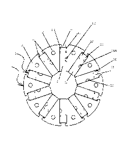
La présente invention concerne une structure de rotor à aimants permanents qui comprend un noyau de fer de rotor (1) et des aimants permanents (2). Le noyau de fer de rotor comprend une pluralité de blocs de guidage magnétique (11). Une rainure radiale (12) servant à monter les aimants permanents est formée entre deux blocs de guidage magnétique adjacents. Les blocs de guidage magnétique sont pourvus, de manière convexe, de crochets d'arrêt (13) au niveau de deux côtés de chaque partie d'ouverture de la rainure radiale. Les aimants permanents comprennent des premiers aimants permanents (21) et des seconds aimants permanents (22). Un côté de chaque premier aimant permanent est une surface fortement magnétique de pôle N (211), et l'autre côté est une surface faiblement magnétique de pôle S (212). Un côté de chaque second aimant permanent est une surface faiblement magnétique de pôle N (221), et l'autre côté est une surface fortement magnétique de pôle S (222). Les premiers aimants permanents et les seconds aimants permanents sont montés alternativement dans les rainures radiales. La surface fortement magnétique de pôle N du premier aimant permanent et la surface faiblement magnétique de pôle N du second aimant permanent dans deux rainures radiales adjacentes s'assemblent au niveau de deux surfaces latérales d'un même bloc de guidage magnétique pour former un pôle magnétique N, et la surface faiblement magnétique de pôle S du premier corps d'aimant permanent et la surface fortement magnétique de pôle S du second corps d'aimant permanent dans deux rainures radiales adjacentes s'assemblent au niveau de deux surfaces latérales d'un même bloc de guidage magnétique pour former un pôle magnétique S, ce qui permet de rendre plus uniforme la distribution du champ magnétique, et de réduire les vibrations et le bruit d'un moteur durant son fonctionnement.


Abrégé anglais


A permanent magnetic rotor structure comprises a rotor iron core (1) and
permanent
magnets (2). The rotor iron core comprises a plurality of magnetic guide
blocks (11). A
radial groove (12) for mounting the permanent magnets is formed between two
adjacent
magnetic guide blocks. The magnetic guide blocks are convexly provided with
stop
hooks (13) at two sides of each opening portion of the radial groove. The
permanent
magnets comprise first permanent magnets (21) and second permanent magnets
(22). One
side of each first permanent magnet is an N-pole strong magnetic surface
(211), and the
other side is an S-pole weak magnetic surface (212). One side of each second
permanent
magnet is an N-pole weak magnetic surface (221), and the other side is an S-
pole strong
magnetic surface (222). The first permanent magnets and the second permanent
magnets
are mounted in the radial grooves alternatively. The N-pole strong magnetic
surface of the
first permanent magnet and the N-pole weak magnetic surface of the second
permanent
magnet in the adjacent two radial grooves joint at two side surfaces of a same
magnetic
guide block to form an N-pole magnetic pole, and the S-pole weak magnetic
surface of
the first permanent magnet body and the S-pole strong magnetic surface of the
second
permanent magnet body in the adjacent two radial grooves joint at two side
surfaces of a
same magnetic guide block to form an S-pole magnetic pole, thereby making
magnetic
field distribution more uniform, and reducing vibration and noise of a motor
during
operation.

Revendications

Note : Les revendications sont présentées dans la langue officielle dans laquelle elles ont été soumises.


CLAIMS
1. A permanent magnet rotor, comprising a rotor core (1) and permanent
magnets
(2), the rotor core comprising a plurality of magnetic induction blocks (11),
a
plurality of radial recesses (12) being formed between every two adjacent
magnetic induction blocks for mounting the permanent magnets (2), the
magnetic induction blocks (11) at both sides of an opening of the radial
recesses protruding to form hook blocks (13), characterized in that the
permanent magnets (2) comprises a plurality of first permanent magnets (21)
and a plurality of second permanent magnets (22), each of the plurality of
first
permanent magnets (21) comprises a first north pole magnetic surface (211)
and a first south pole magnetic surface (212); each of the plurality of second
permanent magnets (22) comprises a second north pole magnetic surface (221)
and a second south pole magnetic surface (222); the magnetic field strength of
the first north pole magnetic surface is greater than the magnetic field
strength
of the first south pole magnetic surface; the magnetic field strength of the
second north pole magnetic surface is smaller than the magnetic field strength
of the second south pole magnetic surface; the plurality of first permanent
magnets (21) and the plurality of second permanent magnets (22) are
alternately disposed in the radial recesses (12); the first north pole
magnetic
surface (211) and the second north pole magnetic surface (221) are separately
attached to two sides of a same magnetic induction block (11) to form a north
magnetic pole; and the first south pole magnetic surface (212) and the second
south pole magnetic surface (222) are separately attached to two sides of
another same magnetic induction block (11) to form a south magnetic pole.
2. The permanent magnet rotor of claim 1, characterized in that each of the
plurality of first permanent magnets (21) comprises a first side (2110), and a
first marker (2111) is disposed on the first side; each of the plurality of
second

permanent magnets (22) comprises a second side (2220), and a second marker
(2221) is disposed on the second side.
3. The permanent magnet rotor of claim 2, characterized in that the first
side
(2110) is disposed on the first north pole magnetic surface (211); and the
second side (2220) is disposed on the second south pole magnetic surface
(222).
4. The permanent magnet rotor of claim 2 or 3, characterized in that the
first
marker (2111) and the second marker (2221) are alternately and uniformly
disposed.
5. The permanent magnet rotor of claim 4, characterized in that the
magnetic
field strength of the first north pole magnetic surface (211) is at least 5%
greater than that of the first south pole magnetic surface (212); and the
magnetic field strength of the second north pole magnetic surface (221) is at
least 5% smaller than that of the second south pole magnetic surface (222).
6. The permanent magnet rotor of claim 1, 2 or 3, characterized in that the
rotor
core (1) and the permanent magnets (2) are connected via an injection layer
(3).
7. The permanent magnet rotor of claim 6, characterized in that the
injection
layer (3) comprises a front end panel (31), a rear end panel (32), and a
middle
connection (33) column connecting the front end panel (31) and the rear end
panel (32).
8. The permanent magnet rotor of claim 2, characterized in that the first
side
(2110) is disposed on the first south pole magnetic surface (212); and the
11

second side (2220) is disposed on the second north pole magnetic surface
(221).
9. The permanent magnet rotor of claim 2 or 3, characterized in that each
of the
plurality of first permanent magnets (21) and the first marker (2111) are
integrated, and each of the plurality of second permanent magnets (22) and the
second marker (2221) are integrated.
10. The permanent magnet rotor of claim 1, characterized in that the first
permanent magnet and the second permanent magnet are obtained as follows:
placing an electric coil in close proximity to a material to produce an
external
magnetic field; and magnetizing the material by the external magnetic field to
obtain the first permanent magnet or the second permanent magnet in which
magnetic field strength of the magnetic surface closer to the electric coil is
at
least 5% greater than the magnetic field strength of the magnetic surface
farther from the electric coil.
12

Description

Note : Les descriptions sont présentées dans la langue officielle dans laquelle elles ont été soumises.


CA 02898944 2015-07-22
PERMANENT MAGNETIC ROTOR STRUCTURE
FIELD OF THE INVENTION
[0001] The invention relates to a permanent magnet rotor.
BACKGROUND OF THE INVENTION
[0002] As shown in FIG. I, a typical permanent magnet rotor includes a rotor
core Al
and permanent magnets A2. The rotor core Al includes a plurality of magnetic
induction
blocks All, and a plurality of radial recesses Al2 are formed between every
two adjacent
magnetic induction blocks All for mounting the permanent magnet's A2. The
magnetic
induction blocks All at both sides of an opening of the radial recesses
protrudes to form
hook blocks A13. The permanent magnets A2 are blocks including a north pole
magnetic
surface and a south pole magnetic surface. Two north pole magnetic surfaces of
two
adjacent permanent magnets A2 are separately attached to two sides of a same
magnetic
induction block All to form a north magnetic pole 100, and two south pole
magnetic
surfaces of two adjacent permanent magnets Al are separately attached to two
sides of
another same magnetic induction block All to form a south magnetic pole 200.
[0003) However, in the process of magnetic domain orientation of a magnetic
shoe blank,
as shown in FIG. 2, when the orientation coil approaches to the permanent
magnet Al,
the magnetic strength of the magnetic surface close to the orientation coil is
relatively
strong, and the magnetic strength of the magnetic surface far from the
orientation coil is
relatively weak. Measurement shows that, the magnetic strength of the strong
magnetic
surface is at least 5% greater than the magnetic strength of the weak magnetic
surface.
1

CA 02898944 2015-07-22
With regard to an embedded rotor, each magnetic pole of the rotor is formed by
two
permanent magnets A2 separately attached to two sides of one magnetic
induction block
All. If the two magnetic surfaces attached to two sides of the magnetic
induction block
All are both strong or both weak, the resulting magnetic strength is
nonuniform.
[0004] In production, the nonuniformity of magnetic strength is often ignored,
that is to
say, the magnetic strength of the north pole magnetic surface and the south
pole magnetic
surface are regarded to be equivalent However, the assembled rotor produces
violent
fluctuation and vibration, thereby producing irregular back electromotive
force
waveform, and resulting in inaccurate and inefficient control.
[0005] FIG. 3 shows two kinds of magnetic poles formed by a first strong
magnetic
surface and a second strong magnetic surface of permanent magnets, and by a
first weak
magnetic surface and a second weak magnetic surface of permanent magnets,
respectively. FIG. 4 shows three kinds of magnetic poles formed by two strong
magnetic
surfaces, two weak magnetic surfaces, and a strong magnetic surface and a weak
magnetic surface, respectively. The magnetic fields formed in FIGS. 3 and 4
are
nonuniform, which is harmful to the operation of the motor. Specifically, the
motor
produces huge electromagnetic noise and vibration, thereby indirectly causing
inaccurate
and inefficient control.
SUMMARY OF THE INVENTION
[0006] In view of the above-described problems, it is one objective of the
invention to
provide a permanent magnet rotor that can produce uniform magnetic
distribution and
weaken electromagnetic noise and vibration when the motor is working.
[0007] In view of the above-described problems, it is one objective of the
invention to
2

CA 02898944 2015-07-22
=
provide a permanent magnet rotor that can speed up the placement of the
permanent
magnets accurately, and prevent the misplacement thereof, thereby improving
the
working efficiency.
[0008] The above objectives are achieved according to following technical
schemes.
[0009] A permanent magnet rotor comprises a rotor core and permanent magnets.
The
rotor core comprises a plurality of magnetic induction blocks, and a plurality
of radial
recesses are formed between every two adjacent magnetic induction blocks for
mounting
the permanent magnets. The magnetic induction blocks at both sides of an
opening of the
radial recesses protrude to form hook blocks. The permanent magnets comprise a
first
permanent magnet and a second permanent magnet. The first permanent magnet
comprises a north pole strong magnetic surface and a south pole weak magnetic
surface.
The second permanent magnet comprises a north pole weak magnetic surface and a
south
pole strong magnetic surface. The first permanent magnet and the second
permanent
magnet are alternately disposed in the radial recesses. The north pole strong
magnetic
surface of the first permanent magnet and the north pole weak magnetic surface
of the
second permanent magnet from two adjacent radial recesses are separately
attached to
two sides of a same magnetic induction block to form a north magnetic pole.
The south
pole weak magnetic surface of the first permanent magnet and the south pole
strong
magnetic surface of the second permanent magnet from two adjacent radial
recesses are
separately attached to two sides of another same magnetic induction block to
form a
south magnetic pole.
[0010] The first permanent magnet comprises a first short side on a top
thereof, and a
first marker is disposed on the first short side; the second permanent magnet
comprises a
second short side on a top thereof, and a second marker is disposed on the
second short
side.
3

CA 02898944 2015-07-22
[0011] The first short side is disposed on the north pole strong magnetic
surface; and the
second short side is disposed on the south pole strong magnetic surface.
[0012] The first marker and the second marker are alternately disposed
uniformly.
[0013] A magnetic strength of the north pole strong magnetic surface of the
first
permanent magnet is at least 5% higher than that of the south pole weak
magnetic surface
of the first permanent magnet; and a magnetic strength of the north pole weak
magnetic
surface of the second permanent magnet is at least 5% less than that of the
south pole
strong magnetic surface of the first permanent magnet.
[0014] The rotor core and the permanent magnets are connected via an injection
layer.
[0015] The injection layer comprises a front end panel, a rear end panel, and
a middle
connection column connecting the front end panel and the rear end panel.
[0016] The first short side is disposed on the south pole weak magnetic
surface; and the
second short side is disposed on the north pole weak magnetic surface.
[0017] The first permanent magnet and the first marker, and the second
permanent
magnet and the second marker, both are integrated.
[0018] Advantages according to embodiments of the invention are summarized as
follows: 1) The permanent magnets comprises a first permanent magnet and a
second
permanent magnet. The first permanent magnet comprises a north pole strong
magnetic
surface and a south pole weak magnetic surface. The second permanent magnet
comprises a north pole weak magnetic surface and a south pole strong magnetic
surface.
The first permanent magnet and the second permanent magnet are alternately
disposed in
the radial recesses. The north pole strong magnetic surface of the first
permanent magnet
and the north pole weak magnetic surface of the second permanent magnet from
two
adjacent radial recesses are separately attached to two sides of a same
magnetic induction
4

CA 02898944 2015-07-22
block to form a north magnetic pole; and the south pole weak magnetic surface
of the
first permanent magnet and the south pole strong magnetic surface of the
second
permanent magnet from two adjacent radial recesses are separately attached to
two sides
of another same magnetic induction block to form a south magnetic pole. Thus,
the
magnetic strengths of the magnetic poles are basically equivalent, the
magnetic
distribution is uniform, thereby weakening electromagnetic noise and vibration
of the
running motor. 2) The first permanent magnet comprises a first short side on
the top
thereof, and a first marker is disposed on the first short side; the second
permanent
magnet comprises a second short side on the top thereof, and a second marker
is disposed
on the second short side, so that the permanent magnets can be disposed
accurately and
rapidly, the misplacement thereof is prevented, thereby improving the working
efficiency.
BRIEF DESCRIPTION OF THE DRAWINGS
[0019] FIG. 1 is a schematic diagram of a permanent magnet rotor in the prior
art;
[0020] FIG. 2 shows a schematic diagram of magnetic domain orientation of a
magnetic shoe blank;
[0021] FIG. 3 is a schematic diagram showing magnetic pole distribution of a
permanent
magnet rotor in the prior art;
[0022] FIG. 4 is a schematic diagram showing magnetic pole distribution of
another
permanent magnet rotor in the prior art;
[0023] FIG. 5 is a schematic diagram of a permanent magnet rotor in accordance
with
one embodiment of the invention;
[0024] FIG. 6 is an exploded view of a permanent magnet rotor in accordance
with one
embodiment of the invention;

CA 02898944 2015-07-22
[0025] FIG. 7 is a stereogram of a first permanent magnet in accordance with
one
embodiment of the invention;
[0026] FIG. 8 is a stereogram of a second permanent magnet in accordance with
one
embodiment of the invention;
[0027] FIG. 9 is a stereogram of an injected permanent magnet rotor in
accordance with
one embodiment of the invention;
[0028] FIG. 10 is an exploded view of an injected permanent magnet rotor in
accordance
with one embodiment of the invention;
[0029] FIG. 11 is a stereogram of a first permanent magnet in accordance with
another
embodiment of the invention; and
[0030] FIG. 12 is a stereogram of a second permanent magnet in accordance with
another
embodiment of the invention.
DETAILED DESCRIPTION OF THE EMBODIMENTS
[0031] For further illustrating the invention, experiments detailing a
permanent magnet
rotor are described below. It should be noted that the following examples are
intended to
describe and not to limit the invention.
Example 1
[0032] As shown in FIGS. 5-10, a permanent magnet rotor comprises a rotor core
1 and
permanent magnets 2. The rotor core comprises a plurality of magnetic
induction blocks
11, and a plurality of radial recesses 12 are formed between every two
adjacent magnetic
induction blocks for mounting the permanent magnets 2. The magnetic induction
blocks
11 at both sides of an opening of the radial recesses protrude to form hook
blocks 13. The
6

permanent magnets 2 comprise a first permanent magnet 21 and a second
permanent
magnet 22. The first permanent magnet 21 comprises a north pole strong
magnetic
surface 211 and a south pole weak magnetic surface 212_ The second permanent
magnet 22 comprises a north pole weak magnetic surface 221 and a south pole
strong
magnetic surface 222. Specifically, the first permanent magnet and the second
permanent magnet are obtained by the following process as shown in FIG. 2:
placing
an electric coil in close proximity to a material to produce an external
magnetic field;
and magnetizing the material by the external magnetic field to obtain the
first
permanent magnet and the second permanent magnet in which magnetic field
strength
of the magnetic surface closer to the electric coil is at least 5% greater
than the
magnetic field strength of the magnetic surface farther from the electric
coil. The first
permanent magnet 21 and the second permanent magnet 22 are alternately
disposed in
the radial recesses 12. The north pole strong magnetic surface 211 of the
first
permanent magnet 21 and the north pole weak magnetic surface 221 of the second
permanent magnet 22 from two adjacent radial recesses 12 are separately
attached to
two sides of a same magnetic induction block 11 to form a north magnetic pole;
and
the south pole weak magnetic surface 212 of the first permanent magnet 21 and
the
south pole strong magnetic surface 222 of the second permanent magnet 22 from
two
adjacent radial recesses 12 are separately attached to two sides of another
same
magnetic induction block 11 to form a south magnetic pole. The first permanent
magnet 21 comprises a first short side 2110 on a top thereof, and a first
marker 2111
is disposed on the first short side. The second permanent magnet 22 comprises
a
second short side 2220 on a top thereof, and a second marker 2221 is disposed
on the
second short side. The first short side 2110 is disposed on the north pole
strong
magnetic surface 211; and the second short side 2220 is disposed on the south
pole
strong magnetic surface 222. From the top view, the first marker 2111 and the
second
marker 2221 are alternately disposed uniformly. The magnetic field strength of
the
north pole strong magnetic surface 211 of the first permanent magnet 21 is at
least 5%
higher than that of the south pole weak magnetic surface 212 of the first
permanent
7
CA 2898944 2018-06-04

magnet 21; and the magnetic field strength of the north pole weak magnetic
surface 221 of the
second permanent magnet 22 is at least 5% less than that of the south pole
strong magnetic
surface 222 of the first permanent magnet 22. The rotor core 1 and the
permanent magnets 2 are
connected via an injection layer 3. The injection layer 3 comprises a front
end panel 31, a rear
end panel 32, and a middle connection column 33 connecting the front end panel
31 and the rear
end panel 32. The first permanent magnet 21 and the first marker 2111, and the
second
permanent magnet 22 and the second marker 2221, both are integrated.
Example 2
[0033] The permanent magnet rotor disclosed in this example is basically the
same as that in
Example 1 except that the first short side 2110 is disposed on the south pole
weak magnetic
surface 212; and the second short side 2220 is disposed on the north pole weak
magnetic surface
221, as shown in FIGS. 11-12.
[0034] Principle of the permanent magnet rotor is summarized as follows. The
permanent
magnets 2 comprise a first permanent magnet 21 and a second permanent magnet
22. The first
permanent magnet 21 comprises a north pole strong magnetic surface 211 and a
south pole weak
magnetic surface 212. The second permanent magnet 22 comprises a north pole
weak magnetic
surface 221 and a south pole strong magnetic surface 222. The first permanent
magnet 21 and the
second permanent magnet 22 are alternately disposed in the radial recesses 12.
The north pole
strong magnetic surface 211 of the first permanent magnet 21 and the north
pole we magnetic
surface 221 of the second permanent magnet 22 from two adjacent radial
recesses 12 are
separately attached to two sides of a same magnetic induction block 11 to form
a north magnetic
pole; and the south pole weak magnetic surface 212 of the first permanent
magnet 21 and the
south pole strong magnetic surface 222 of the second permanent magnet 22 from
two adjacent
radial recesses 12 are separately attached to two sides of another same
magnetic induction block
11 to form a south magnetic pole. Thus, the magnetic strengths of the magnetic
poles are
basically equivalent, the magnetic distribution is uniform, thereby weakening
electromagnetic
noise and vibration of the running motor. 2) The first permanent magnet
comprises a first short
side on the top thereof, and a first marker is disposed on the first short
side; the second
permanent magnet comprises a second short side on the top thereof, and a
second marker is
8
CA 2898944 2018-08-09

disposed on the second short side, so that the permanent magnets can be
disposed accurately and
rapidly, the misplacement thereof is prevented, thereby improving the working
efficiency.
,
9
CA 2898944 2018-08-09

Dessin représentatif
Une figure unique qui représente un dessin illustrant l'invention.
États administratifs

2024-08-01 : Dans le cadre de la transition vers les Brevets de nouvelle génération (BNG), la base de données sur les brevets canadiens (BDBC) contient désormais un Historique d'événement plus détaillé, qui reproduit le Journal des événements de notre nouvelle solution interne.

Veuillez noter que les événements débutant par « Inactive : » se réfèrent à des événements qui ne sont plus utilisés dans notre nouvelle solution interne.

Pour une meilleure compréhension de l'état de la demande ou brevet qui figure sur cette page, la rubrique Mise en garde , et les descriptions de Brevet , Historique d'événement , Taxes périodiques et Historique des paiements devraient être consultées.

Historique d'événement

Description Date
Demande visant la révocation de la nomination d'un agent 2023-07-28
Exigences relatives à la révocation de la nomination d'un agent - jugée conforme 2023-07-28
Inactive : CIB expirée 2022-01-01
Requête visant le maintien en état reçue 2020-01-16
Représentant commun nommé 2019-10-30
Requête visant le maintien en état reçue 2019-02-14
Accordé par délivrance 2019-02-12
Inactive : Page couverture publiée 2019-02-11
Préoctroi 2018-12-27
Inactive : Taxe finale reçue 2018-12-27
Un avis d'acceptation est envoyé 2018-09-19
Lettre envoyée 2018-09-19
Un avis d'acceptation est envoyé 2018-09-19
Inactive : QS réussi 2018-09-14
Inactive : Approuvée aux fins d'acceptation (AFA) 2018-09-14
Modification reçue - modification volontaire 2018-08-09
Inactive : Demande ad hoc documentée 2018-06-04
Modification reçue - modification volontaire 2018-06-04
Requête visant le maintien en état reçue 2018-02-26
Inactive : Dem. de l'examinateur par.30(2) Règles 2017-12-04
Inactive : Rapport - Aucun CQ 2017-11-29
Lettre envoyée 2017-03-07
Requête visant le maintien en état reçue 2017-02-27
Exigences pour une requête d'examen - jugée conforme 2017-02-27
Toutes les exigences pour l'examen - jugée conforme 2017-02-27
Requête d'examen reçue 2017-02-27
Requête visant le maintien en état reçue 2016-02-26
Inactive : Page couverture publiée 2015-08-14
Inactive : CIB en 1re position 2015-08-04
Inactive : Notice - Entrée phase nat. - Pas de RE 2015-08-04
Inactive : CIB attribuée 2015-08-04
Demande reçue - PCT 2015-08-04
Exigences pour l'entrée dans la phase nationale - jugée conforme 2015-07-22
Demande publiée (accessible au public) 2015-03-05

Historique d'abandonnement

Il n'y a pas d'historique d'abandonnement

Taxes périodiques

Le dernier paiement a été reçu le 2018-02-26

Avis : Si le paiement en totalité n'a pas été reçu au plus tard à la date indiquée, une taxe supplémentaire peut être imposée, soit une des taxes suivantes :

  • taxe de rétablissement ;
  • taxe pour paiement en souffrance ; ou
  • taxe additionnelle pour le renversement d'une péremption réputée.

Les taxes sur les brevets sont ajustées au 1er janvier de chaque année. Les montants ci-dessus sont les montants actuels s'ils sont reçus au plus tard le 31 décembre de l'année en cours.
Veuillez vous référer à la page web des taxes sur les brevets de l'OPIC pour voir tous les montants actuels des taxes.

Historique des taxes

Type de taxes Anniversaire Échéance Date payée
Taxe nationale de base - générale 2015-07-22
TM (demande, 2e anniv.) - générale 02 2016-02-29 2016-02-26
Requête d'examen - générale 2017-02-27
TM (demande, 3e anniv.) - générale 03 2017-02-28 2017-02-27
TM (demande, 4e anniv.) - générale 04 2018-02-28 2018-02-26
Taxe finale - générale 2018-12-27
TM (brevet, 5e anniv.) - générale 2019-02-28 2019-02-14
TM (brevet, 6e anniv.) - générale 2020-02-28 2020-01-16
TM (brevet, 7e anniv.) - générale 2021-03-01 2021-01-18
TM (brevet, 8e anniv.) - générale 2022-02-28 2021-12-14
TM (brevet, 9e anniv.) - générale 2023-02-28 2023-01-09
TM (brevet, 10e anniv.) - générale 2024-02-28 2023-12-26
Titulaires au dossier

Les titulaires actuels et antérieures au dossier sont affichés en ordre alphabétique.

Titulaires actuels au dossier
ZHONGSHAN BROAD-OCEAN MOTOR MANUFACTURING CO., LTD.
Titulaires antérieures au dossier
MINGPAN PAN
Les propriétaires antérieurs qui ne figurent pas dans la liste des « Propriétaires au dossier » apparaîtront dans d'autres documents au dossier.
Documents

Pour visionner les fichiers sélectionnés, entrer le code reCAPTCHA :


Pour visualiser une image, cliquer sur un lien dans la colonne description du document. Pour télécharger l'image (les images), cliquer l'une ou plusieurs cases à cocher dans la première colonne et ensuite cliquer sur le bouton "Télécharger sélection en format PDF (archive Zip)" ou le bouton "Télécharger sélection (en un fichier PDF fusionné)".

Liste des documents de brevet publiés et non publiés sur la BDBC .

Si vous avez des difficultés à accéder au contenu, veuillez communiquer avec le Centre de services à la clientèle au 1-866-997-1936, ou envoyer un courriel au Centre de service à la clientèle de l'OPIC.


Description du
Document 
Date
(aaaa-mm-jj) 
Nombre de pages   Taille de l'image (Ko) 
Description 2015-07-21 9 307
Revendications 2015-07-21 3 76
Abrégé 2015-07-21 1 32
Dessins 2015-07-21 10 146
Dessin représentatif 2015-07-21 1 20
Description 2018-06-03 10 336
Revendications 2018-06-03 3 96
Description 2018-08-08 9 330
Abrégé 2018-09-18 1 34
Dessin représentatif 2019-01-15 1 7
Avis d'entree dans la phase nationale 2015-08-03 1 192
Rappel de taxe de maintien due 2015-10-28 1 111
Accusé de réception de la requête d'examen 2017-03-06 1 187
Avis du commissaire - Demande jugée acceptable 2018-09-18 1 162
Modification / réponse à un rapport 2018-08-08 5 113
Demande d'entrée en phase nationale 2015-07-21 5 127
Modification - Abrégé 2015-07-21 2 106
Traité de coopération en matière de brevets (PCT) 2015-07-21 1 42
Rapport de recherche internationale 2015-07-21 2 73
Paiement de taxe périodique 2016-02-25 2 55
Requête d'examen 2017-02-26 2 55
Paiement de taxe périodique 2017-02-26 2 62
Demande de l'examinateur 2017-12-03 4 222
Paiement de taxe périodique 2018-02-25 2 51
Modification / réponse à un rapport 2018-06-03 18 606
Taxe finale 2018-12-26 2 49
Paiement de taxe périodique 2019-02-13 2 53
Paiement de taxe périodique 2020-01-15 2 55