Note : Les descriptions sont présentées dans la langue officielle dans laquelle elles ont été soumises.
CA 02899208 2015-07-23
WO 2014/117043 PCT/US2014/013081
FLUID WASTE COLLECTION AND DISPOSAL SYSTEM AND METHOD
BACKGROUND
[0001] Systems for collecting and disposing of bodily fluids and other fluids
that are aspirated
from a patient during surgical procedures are well known. Conventional fluid
waste collection
systems typically use some type of container or canister into which the
aspirated fluids are
collected. As the fluid collection canisters become filled during the course
of a surgical
procedure, the filled canisters are replaced with empty canisters. Depending
on the volume of
the canisters and the amount of fluid being collected, the surgical procedure
may have to be
interrupted to replace a filled canister with an empty canister.
[0002] It should be appreciated that the aspirated fluids may be contaminated
with pathogens,
such as HIV, HPV, Hepatitis, MRSA and other infectious agents. During the
surgical procedure
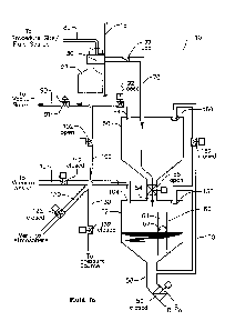
and/or after the surgical procedure is completed, the fluid filled canisters
are typically carted
from the operating room to a central collection location for disposal or,
alternatively, the
canisters may be emptied, cleaned, and re-used. Accordingly, handling of fluid
collection
canisters by hospital personnel creates a risk that the handlers may come into
contact with the
contaminated fluids contained in the canisters due to spillage, leaks or
splashing while carrying,
emptying or cleaning the canisters.
[0003] In an effort to minimize exposure to pathogens in the aspirated fluid,
the canisters may be
partially pre-filled with a disinfectant to destroy any pathogens as the fluid
enters the canisters.
Alternatively solidifying agents or coagulants may be added to the canisters
to minimize the
potential for spillage, splashing and leakage. However, such additives
increase the disposal costs
because the canisters must then be treated as hazardous waste and must be
incinerated or
delivered to a landfill. Furthermore, there is also the additional labor and
associated costs with
having to purchase, store, and handle the canisters themselves. In any event,
whether
disinfectants or solidifiers are added, there remains a risk that handlers of
the canisters will still
come into contact with the fluid waste.
[0004] In an attempt to overcome the risk of exposure to pathogens and the
additional costs and
labor associated with the use of canisters to collect fluid waste, systems
have been developed to
1
CA 02899208 2015-07-23
WO 2014/117043 PCT/US2014/013081
collect the fluid waste in reservoirs which can be drained directly into the
facility's sewer system.
However, such systems operate in a manner very similar to the canister systems
(apart from
having to handle the canisters). Specifically, such systems utilize redundant
reservoirs and
piping so that when the first reservoir is filled, the operator has to
manually disconnect the
suction hose from the first reservoir and re-connect the suction hoses to the
second reservoir
which presents the same undesirable interruption of the medical procedure as
when using a
canister-type collection system.
[0005] In an attempt to minimize the interruption of the medical procedure,
others have
attempted to automate the process using redundant systems, with each system
having its own
reservoir, vacuum line, drain pipe, fluid level sensor and associated valving.
In use, the first
reservoir is under negative pressure and collects the fluid. When the first
reservoir reaches a
predetermined fill level as detected by the first fluid level sensor, the
system is programmed to
switch the negative pressure from the first reservoir to the second reservoir,
such that the second
reservoir begins to collect the fluid while the fluid in the first reservoir
is drained. This
automatic switching between filling and draining the redundant systems is
repeated until the
medical procedure is completed. While the switching between reservoirs is much
quicker using
the automated process than doing so manually, and while the capacity to
collect fluid is
theoretically unlimited, such automatic switching systems nevertheless still
cause an undesirable
brief interruption of the suction while the system switches between the
reservoirs.
[0006] Accordingly, there remains a need for an efficient system for
collecting and disposing of
aspirated fluid waste from medical procedures, which eliminates the need for
handling of
canisters to avoid the potential risk of exposure to pathogens, which has an
unlimited capacity,
and which avoids any interruption of suction during the medical procedure.
DESCRIPTION OF THE DRAWINGS
[0007] FIG. 1 is a top perspective view of one embodiment of a housing and
manifold for a fluid
waste collection and disposal system.
[0008] FIG. 2 is a bottom perspective view of the housing of the fluid waste
collection and
disposal system of FIG. 1.
2
CA 02899208 2015-07-23
WO 2014/117043 PCT/US2014/013081
[0009] FIGs. 3A and 3B are enlarged perspective views of the manifold of FIG.
1 showing the
cleaning solution hanger in an attachment position and in an inverted use
position.
[0010] FIG. 4 illustrates an embodiment of a touch screen display of the fluid
waste collection
and disposal system of FIG. 1.
[0011] FIGs. 5-9 schematically illustrate alternative embodiments of the fluid
waste collection
and disposal system wherein the fluid reservoirs are shown in stacked
relation.
[0012] FIG. 10 schematically illustrates another embodiment of a fluid waste
collection and
disposal system with the fluid reservoirs in a side-by-side relation.
[0013] FIGs. 11A-11D schematically illustrate the fluid waste collection and
disposal system of
FIG. 5 showing various steps of using the system to collect and dispose of
fluid waste.
[0014] FIGs. 12A-12D schematically illustrate the fluid waste collection and
disposal system of
FIG. 9 showing various steps of using the system to collect and dispose of
fluid waste.
[0015] FIGs. 13A-13E schematically illustrate the fluid waste collection and
disposal system of
FIG. 5 showing various steps a process for cleaning the system.
[0016] FIGs. 14A-14F schematically illustrate the fluid waste collection and
disposal system of
FIG. 9 showing various steps of a process for cleaning the system.
DESCRIPTION
[0017] Referring now to the drawings, wherein like reference numerals
designate identical or
corresponding parts throughout the several views, FIGs. 1 and 2 are top and
bottom perspective
views, respectively, of an embodiment of a fluid waste collection and disposal
system designated
generally by reference numeral 10. The system 10 is shown having a housing 12
adapted for
mounting on a wall or in a partially recessed fashion into a wall in the
operating room or other
facility in which fluid aspiration procedures are performed. A mounting flange
14 is provided
for securing the housing to any suitable surface or structure using
appropriate fasteners. It
should be appreciated, however, that the system 10 may be a free standing
stationary or portable
system.
3
CA 02899208 2015-07-23
WO 2014/117043 PCT/US2014/013081
[0018] The housing 12 includes a front panel 16 for access to the interior of
the housing and the
components therein (discussed later). The front panel 16 may include a lock 18
or other security
mechanisms to prevent unauthorized access to the interior of the housing 12.
The front panel 16
includes a touch screen display 20, a fluid viewing window 22, and one or more
vacuum
adjustment controllers 24. The vacuum adjustment controller(s) 24, may be
rotatable dials, push
buttons, slide mechanisms or part of the touch screen display 20. As discussed
in more detail
later, the front panel 16 also supports a manifold 30 comprising plurality of
suction ports to
which suction hoses 80 are attached. The manifold 30 may support a cleaning
solution hanger
(discussed later) for removably receiving a cleaning solution bottle 28. One
side panel of the
housing 12 may include a vacuum connection port 32, a power source connection
34 and an on-
off switch 36. The power source may be 24 Volt DC or any other suitable power
source. A
bottom panel of the housing 12 may include a main drain port 38 and a
secondary drain port 40.
It should be appreciated that the particular location of the foregoing items
may vary depending
on the configuration of the housing and the components therein and where and
how the system
is installed and/or mounted.
[0019] FIGs. 3A and 3B are enlarged perspective views of the manifold 30 of
FIG. 1. The
manifold 30 includes outlet ports 302 which connect to the fluid inlet line
70. Each of the outlet
ports 302 are in fluid communication with a pair of suction ports 304 to which
the suction hoses
80 attach as shown in FIG. 3A. It should be appreciated that rather than
connecting the suction
hoses 80 to the suction ports 304 directly, the suction hoses 80 may connect
to a filter (not
shown) which then connects to the suction ports 304. The manifold 30 also
supports a cleaning
solution hanger 310, which includes outwardly projecting arms 312 which
support a block 314
rotatable about a pin 316. One end of the block includes a threaded receptacle
318 (FIG. 3B) for
threadably receiving a threaded end of a cleaning solution bottle 28. After
threading the bottle
28 to the block 314, the bottle 28 and block 314 may be rotated such that the
bottle 28 is inverted
with respect to the manifold 30 as shown in FIG. 3B. Passages 320 (FIG. 3B)
communicate the
cleaning solution from the inverted bottle 28 through the block 314 and
through nipples 322 on
the opposite side of the block 314. Cleaning solution tubes 324 are connected
at one end to the
nipples 322 on the block 314 and are connected at the other end to nipples 326
on a door 328 that
is slidable as indicated by arrow 330. As shown in FIG. 3B, when the bottle 28
is inverted, the
cleaning solution tubes 324 pass through an opening 332 in the manifold 30.
Also as shown in
4
CA 02899208 2015-07-23
WO 2014/117043 PCT/US2014/013081
FIG. 3B, during the Cleaning Cycle Process (described later), the suction
hoses 80 (or filter, if
used) are disconnected from the suction ports 304 and door 328 is moved to the
closed position
such that the door nipples 326 are aligned with the suction ports 304. An o-
ring may be provided
on the underside of the door 328 around the openings of the door nipples 326
to provide a fluid-
tight connection between the door nipples 326 and the suction ports 304. A
switch (not shown)
may be provided in the hanger 310 such that when the block 314 and bottle 28
are inverted, a
signal is generated permitting the cleaning process to continue. It should be
appreciated, that
instead of using a manifold 30, one or more suction ports 304 may be provided
in the face of the
panel 16 which connect to the fluid inlet line 70. In such an embodiment, the
suction hoses 80
(and/or filter) may be connected directly to the panel suction ports 304 (see
FIG. 10). Similarly,
the cleaning solution tubes 324 may be connected directly to the suction ports
304 after removal
of the suction hoses 80 from the panel suction ports 304.
[0020] The system 10 includes a programmable logic controller ("PLC") (not
shown) which
interfaces with the touch screen display 20 and other circuitry. The circuitry
and associated
programming for the PLC for providing the features and performing the
functions described
below in connection with the "Fluid Collection and Disposal Process" and
"Cleaning Cycle
Process" would be readily understood and recognized by those skilled in the
art and therefore
further discussion on the circuitry is not warranted. Rather than using a PLC
and associated
circuitry, it should be appreciated that solid state circuitry could be
utilized which could further
reduce the total size of system 10, if desired, as well as provide additional
desired functionality.
[0021] In FIG. 4, an embodiment of a display screen is illustrated for the
touch screen display
20. As illustrated, the touch screen display 20 includes a "Fluid Collected"
indicator 200, a
"System Run Time" indicator 202, a "Table Suction" indicator 204, a "Source
Suction" indicator
206, a status/information indicator 208, and a plurality of selectable
operational functions,
including a "Start Suction" selection 210, a "Stop Suction" selection 212, a
"Start Clean Cycle"
selection 214, a "Clear Values" selection 216 and an "Advanced Operations"
selection 218. The
Fluid Collected indicator 200 indicates the volume of fluid collected
(preferably in milliliters)
since pressing the Start Suction selection 210. The System Run Time indicator
202 indicates the
time passed, preferably displayed in hours, minutes and seconds, since
pressing the Start Suction
selection 210. The Table Suction indicator 204, indicates the vacuum or
negative pressure,
CA 02899208 2015-07-23
WO 2014/117043 PCT/US2014/013081
preferably in inches or mm Hg, at the suction ports 304 which is controlled by
the vacuum adjust
controller 24 on the front panel 16. If multiple suctions ports 304 are
provided, a separate Table
Suction indicator 204 may be provided to indicate the negative pressure at
each suction port.
The Source Suction display 206, indicates, the suction provided by the
facility's vacuum system,
preferably in inches or mm Hg, to which the vacuum port 32 is connected. The
status/information indicator 208 provides information to the operator such as
the current
operation selection, system status or any alarm conditions.
[0022] FIGs. 5-10 schematically illustrate alternative embodiments of the
fluid waste collection
and disposal system 10. In each of the embodiments, the system 10 includes
first and second
reservoirs 50, 52, a conduit 54, fluid transfer valve 56, a drain pipe 58, a
fluid discharge
mechanism 59, a fluid sensor 60, a fluid inlet line 70, an inlet line valve
72, a vacuum line 90, a
vacuum line valve 92, an auxiliary line 100, an auxiliary line valve 102 and a
recirculation line
150. In the different embodiments, additional lines and valves or different
combinations thereof,
cooperate to control air flow and/or fluid flow through the system 10 as
described in detail later
under the "Fluid Collection and Disposal Process".
[0023] In each of the embodiments, the first reservoir 50 is fluidly connected
to the second
reservoir 52 by the conduit 54. The fluid transfer valve 56, is disposed along
the conduit 54 to
control the transfer of collected waste fluid from the first reservoir 50 to
the second reservoir 52
(discussed later). The fluid transfer valve 56 may be a solenoid or motor
driven valve, a check
valve or other suitable valve. The drain pipe 58 is connected to the second
reservoir 52 through
which the collected fluid waste is discharged from the second reservoir 52
into a suitable drain or
waste pipe (not shown) for disposal. The fluid discharge mechanism 59 is
disposed along the
drain pipe 58 to control the discharge of the collected fluid waste from the
second reservoir 52
into the drain or waste pipe. The fluid discharge mechanism 59 may be an
electronically
controllable valve, such as a solenoid or motor driven valve, or a check valve
or other suitable
valve. Alternatively, the fluid discharge mechanism 59 may comprise a pump or
the
combination of a valve and pump.
[0024] The fluid sensor 60 is disposed to detect the amount of fluid collected
from the patient or
fluid source during the procedure. The fluid sensor 60 may be a mechanical
float-type sensor,
6
CA 02899208 2015-07-23
WO 2014/117043 PCT/US2014/013081
such as a ball-float sensor, or the fluid sensor 60 may be an electronic
sensor such as a capacitive
sensor, an optic sensor, an ultrasonic sensor, a piezo-resistance sensor, or
the fluid sensor 60 may
be a mass/weight measuring sensor, such as a load cell or the fluid sensor 60
may be a flow
sensor, such as a flow meter disposed in the fluid inlet line 70, or any other
suitable sensor for
detecting the volume, level or mass/weight of the fluid collected from the
fluid source during the
procedure. In the embodiment of FIGs. 5-7, the fluid sensor 60 is shown as a
ball-float sensor
disposed within the second reservoir 52. In this embodiment, a ball 62 floats
up and down
within a sensor tube 64 to activate switches (not shown) depending on the
fluid level in the
second reservoir 52. In the embodiment illustrated in FIG. 8, the fluid sensor
60, is shown as
comprising an electronic sensor. In this embodiment, the fluid sensor 60
comprises a low level
sensor 66 and a high level sensor 68 disposed in the second reservoir 52. In
the embodiment
illustrated in FIG. 9, the fluid sensor 60 is shown as a load cell (designated
by arrows) to detect
the mass/weight of the fluid in the first and second reservoirs. In the
embodiment of FIG. 10, the
fluid sensor 60 is shown as a flow meter to detect the volume of fluid passing
through the fluid
inlet line 70. It should be appreciated that if a load cell or other
mass/weight measuring sensor is
used, the reservoir supports within the housing, as well as the conduit 54,
drain pipe 58 and other
components may need to be flexible so the mass/weight of the fluid can be
accurately detected or
determined.
[0025] The fluid inlet line 70 is fluidly connected at one end to the manifold
30 and at its other
end to the first reservoir 50. The inlet line valve 72, such as a check valve,
is positioned along
the fluid inlet line 70. On the exterior of the housing 12, single use
disposable suction hoses 80
connect to the suction ports 304 in the manifold 30. Rather than connecting
the suction hoses 80
directly to the suction ports 304, a single use disposable filter 76 may be
inserted into the suction
ports 304 and the suction hoses may be attached to the filter. An end effector
(not shown) on the
distal end of the suction hose 80, is used to suction or aspirate the waste
fluid from the patient.
[0026] The vacuum line 90 extends between a regulated vacuum source (not
shown) and a
vacuum port 94 of the first reservoir 50. Disposed along the vacuum line 90 is
the regulator 91
and the electronically controllable vacuum line valve 92, such as a solenoid
or motor driven
valve. The auxiliary line 100 branches off the vacuum line 90 and connects to
an auxiliary port
104 of the second reservoir 52. Disposed along the auxiliary line 100 is the
electronically
7
CA 02899208 2015-07-23
WO 2014/117043 PCT/US2014/013081
controllable auxiliary line valve 102, such as a solenoid or motor driven
valve.
[0027] Recirculation lines 150 and an electronically controllable valve or one
or more
recirculation pumps are provided for recirculating cleaning solution during
the "Cleaning Cycle
Process" (described later).
[0028] The various embodiments illustrated in FIGS. 1-10 are hereinafter
described. In the
embodiment of FIG. 5, the fluid transfer valve 56 and the fluid discharge
mechanism 59
comprise electronically controllable valves as previously described. In
addition to the
components identified above which are common among all the embodiments, the
embodiment of
FIG. 5 also includes a vacuum assist line 110 connecting a vacuum assist
source (not shown) to
the auxiliary line 100. Disposed along the vacuum assist line 110 is a an
electronically
controllable vacuum assist line valve 112, such as a solenoid or motor driven
valve. A vent line
120 which vents to atmosphere also connects to the auxiliary line 100.
Disposed along the vent
line 120 is an electronically controllable vent line valve 122 such as a
solenoid or motor driven
valve. Additionally, a pressure line 130 connects a pressure source, such as
an air compressor
(not shown) to the auxiliary line 100. Disposed along the pressure line 130 is
an electronically
controllable pressure line valve 132 such as a solenoid or motor driven valve.
Also in the
embodiment of FIG. 5, the recirculation line 150 fluidly connects the first
and second reservoirs
50, 52 and an electronically controllable valve 152 is disposed along the
recirculation line 150 to
control the flow of cleaning solution during the Cleaning Cycle Process.
[0029] The embodiment of FIG. 6 is substantially the same as FIG. 5 except
that the vacuum
assist and associated vacuum assist line 110 and vacuum assist line valve 112
are eliminated.
[0030] The embodiment of FIG. 7 is likewise substantially similar to FIG. 5
except that the
vacuum assist and pressure source and associated lines 110, 130 and valves
112, 132 are
eliminated.
[0031] The embodiment of FIG. 8 is substantially the same as FIG. 5, except
that a recirculation
pump 160 rather than the recirculation line valve 152 is used to control the
flow of cleaning
solution during the Cleaning Cycle Process.
8
CA 02899208 2015-07-23
WO 2014/117043 PCT/US2014/013081
[0032] In the embodiment of FIG. 9, the fluid transfer valve 56 and fluid
discharge mechanism
59 comprise check valves. Additionally, the vent line 120 and associated vent
line valve 122 are
eliminated. Also in the embodiment of FIG. 9, separate recirculation lines 150
and separate
recirculation pumps 160 are used to control the flow of cleaning solution
during the Cleaning
Cycle Process.
[0033] The embodiment of FIG. 10, is substantially the same as the embodiment
of FIG. 5,
except that the first and second reservoirs 50, 52 are arranged in a side-by-
side relationship as
opposed to a stacked relationship.
[0034] Although not shown, corresponding embodiments to those of FIGs. 6-9 may
also be
utilized for the embodiment of FIG. 10 where the reservoirs 50, 52 are
arranged in the side-by-
side relation. It should also be appreciated that the various components of
the different
embodiments identified above may be interchangeable among the embodiments and
arranged in
various configurations.
[0035] The first and second reservoirs 50, 52 and associated components in the
various
embodiments are constructed of suitable material of sufficient thickness to
safely withstand the
negative pressures typically used for the vacuum systems of a medical
facility, which typically
are not greater than 25 inches (635 mm) of mercury (Hg). Additionally, the
reservoirs and
associated components are preferably designed to withstand positive pressures
of up to 20 psi. A
suitable material for the reservoirs may be transparent acrylic to allow the
surgeon or other
medical personnel to view the aspirated fluid as it is collected for assessing
its color or other
characteristics. The first and second reservoirs 50, 52 are preferably
configured with sloped
bottom walls to permit the complete drainage of collected waste fluid as
discussed in detail later.
[0036] A light strip (not shown) which may comprise a plurality of white light
emitting diodes
(LEDs) may be disposed behind the reservoirs 50, 52 to back-light the fluid in
the reservoirs 50,
52 so it can be better viewed through the viewing window 22 in the front panel
16. If there is an
alarm condition, for example, if there is a leak or if the vacuum has been
interrupted due to fluid
back-up, the LEDs are preferably caused to light and flash to visually
indicate an alarm
condition. Under any alarm condition, the PLC is preferably programmed to
flash an error
message on the touch screen display 20.
9
CA 02899208 2015-07-23
WO 2014/117043 PCT/US2014/013081
Fluid Collection and Disposal Process
[0037] The process of collecting and disposing of the fluid waste using the
system 10 is
described below with reference to FIGs. 11A-11D which correspond to the
embodiment of FIG.
5. A brief description of the process for using the embodiments of FIGs. 6-8
and 10 follow the
description of the embodiment of FIG. 5. A more detailed discussion of the
fluid collection and
disposal processes is provided for the embodiment of FIG. 9 with reference to
FIGs. 12A-12D in
view of the structural and functional difference of the embodiment of FIG. 9
as compared to the
other embodiments.
[0038] With respect to all the embodiments, the system 10 may be powered on by
pressing the
on-off switch 36 to the "On" position or, alternatively, by activating the
touch screen 20. When
the system 10 is powered on or is otherwise activated, the touch screen 20
preferably displays a
"system ready" message in the status/information indicator 208 to indicate to
the operator that
the system is ready for operation.
Fluid In Phase - FIG. 5 Embodiment
[0039] Referring to FIG. 11A, upon selecting the Start Suction operation 210,
the initial "Fluid
In" phase is initiated by the PLC generating a signal to open the
electronically controllable fluid
transfer valve 56 and auxiliary line valve 102 permitting communication of the
vacuum source
with the second reservoir 52, and to the first reservoir 50 through the open
fluid transfer valve
56. The electronically controllable valves of the fluid discharge mechanism
59, vacuum assist
line valve 112, the vent line valve 122 and the pressure line valve 132 are in
the closed position.
Because the fluid transfer valve 56 is in the open position, it should be
appreciated that the first
and second reservoirs 50, 52 will have the same negative pressure due to the
air being evacuated
(as indicated by the arrows) by the vacuum source. The negative pressure
inside the reservoirs
50, 52 creates suction through the inlet line 70, which overcomes the bias of
the normally closed
inlet line check valve 72, such that suction is provided to the suction ports
304 of the manifold
30.
[0040] The operator attaches the suction hose 80 to the suction ports 304. If
a filter is used, the
filter is connected to the suction ports 304 and the suction hoses are
connected to inlets on the
CA 02899208 2015-07-23
WO 2014/117043 PCT/US2014/013081
filter. The distal end of the suction hose 80 includes an end effector (not
shown) which typically
includes a regulator for controlling the amount of suction through the end
effector. The operator
may also adjust the amount of Table Suction 204 using the vacuum adjust
controller(s) 24.
When the end effector on the suction hose 80 is placed in contact with fluid,
fluid is drawn
through the suction hose 80 and into the first reservoir 50 and then into the
second reservoir 52
due to the fluid transfer valve 56 being open. The fluid entering the first
and/or second
reservoirs 50, 52 is preferably visible through the window 22 in the front
panel. As noted earlier,
a light strip may be used to back-light the aspirated fluid entering in the
reservoirs so it can be
better viewed by the operator.
Relief and Measure Phase - FIG. 5 Embodiment
[0041] When the fluid level in the second reservoir 52 reaches a predetermined
fill level as
detected by the fluid sensor 60 (e.g., by the ball float 62 floating upward
within the sensor tube
64 until the ball float 62 triggers a switch in the sensor tube 64), a signal
is generated which
begins the "Relief and Measure" phase as illustrated in FIG. 11B. The
generated signal causes
the PLC to open the vacuum line valve 92. After the vacuum line valve 92 is
opened, the PLC
generates a signal to cause the fluid transfer valve 56 and the auxiliary line
valve 102 to close,
thereby isolating the second reservoir 52 from the vacuum source and the first
reservoir 50. It
should be appreciated that the first reservoir remains under negative pressure
via the open
vacuum line valve 92, such that communication of the vacuum source with the
first reservoir is
not interrupted. When the fluid transfer valve 56 and auxiliary line valve 102
are closed, a signal
is generated to cause the PLC to open the vent line valve 122. Upon opening of
the vent line
valve 122, air enters the second reservoir 52 to relieving the negative
pressure until it is brought
to atmospheric pressure. The volume of fluid in the second reservoir 52 is
then determined or
otherwise measured and recorded by the fluid measuring system 400 as described
later.
Drain Phase - FIG. 5 Embodiment
[0042] Once the volume of the fluid in the second reservoir has been
determined and recorded,
the "Drain" phase as illustrated in FIG. 11C is initiated by the PLC
generating a signal to cause
the electronically controllable valve of the fluid discharge mechanism 59 to
open to permit the
fluid to begin to drain from the second reservoir 52 via gravity. To more
rapidly evacuate the
11
CA 02899208 2015-07-23
WO 2014/117043 PCT/US2014/013081
fluid from the second reservoir 52, a signal may be generated by the PLC to
cause the vent line
valve 122 to close and to cause the pressure line valve 132 to open. With the
pressure line valve
132 open, the pressure source, such as compressed air, enters the second
reservoir 52 to quickly
and completely forcefully evacuate the fluid from the second reservoir 52
through the open valve
of the fluid discharge mechanism.
Second Reservoir Preparation Phase - FIG. 5 Embodiment
[0043] When the fluid in the second reservoir 52 has been evacuated (e.g., by
the ball float 62
within the sensor tube 64 dropping to trigger a switch at the bottom of the
sensor tube 64
indicating that the fluid has been evacuated), a signal is generated which
begins the "Second
Reservoir Preparation" phase as depicted in FIG. 11D. The generated signal
causes the PLC to
close the valve of the fluid discharge mechanism 59 and to close the pressure
line valve 132, and
to subsequently cause the vacuum assist line valve 112 to open. With the
vacuum assist line
valve 112 open, the vacuum assist source draws air out of the second reservoir
52 until the
negative pressure in the second reservoir is substantially equal to the
negative pressure in the
first reservoir in communication with the vacuum source. Upon the equalization
of the negative
pressures in the first and second reservoirs (which may be detected by a
pressure transducer or
other suitable sensor), a signal is generated to cause the PLC to open the
auxiliary line valve 102
and the fluid transfer valve 56 to permit the fluid that has been collecting
in the first reservoir 50
to flow into the second reservoir 52 thereby repeating the process beginning
with the "Fluid In"
phase as depicted in FIG. 11A, except that the vacuum line valve 92 remains
open until the
procedure is completed and Stop Suction 212 is selected on the touch pad. It
should be
appreciated that it is desirable to equalize the negative pressure in the
first and second reservoirs
prior to opening the fluid transfer valve 56 to avoid or minimize a sudden
drop or change in
negative pressure in the first reservoir 50 (which could result in
inconsistent suction through the
suction hose 80 at the procedure site) which may occur if there is a
significant pressure
differential between the first and second reservoirs.
[0044] The "Fluid In", "Relief and Measure", "Drain" and "Second Reservoir
Preparation"
phases as depicted in FIGs. 11A-11D are repeated as necessary until the
medical procedure is
completed.
12
CA 02899208 2015-07-23
WO 2014/117043 PCT/US2014/013081
[0045] The fluid collection and disposal process of the embodiment of FIG. 6
is substantially
similar to that of the embodiment of FIG. 5, except that because the vacuum
assist has been
eliminated in the embodiment of FIG. 6, after the fluid is drained from the
second reservoir 52,
the "Second Reservoir Preparation" phase is performed by the PLC generating a
signal to open
the auxiliary line valve 102 to equalize the negative pressure in the second
reservoir 52 with the
negative pressure in the first reservoir 50 before the fluid transfer valve 56
is opened to begin
repeating the "Fluid In" phase.
[0046] Similarly, the fluid collection and disposal process of the embodiment
of FIG. 7 is
substantially similar to that of the embodiment of FIG. 6, except that because
the vacuum assist
and the pressure source have been eliminated in the embodiment of FIG. 7, the
fluid is drained
from the second reservoir 52 during the "Drain" phase via gravity alone and
therefore the vent
line valve 122 remains open until the fluid is drained from the second
reservoir. When the fluid
is drained from the second reservoir 52, the PLC generates a signal to close
the vent line valve
122 and to initiate the "Second Reservoir Preparation" phase by opening the
auxiliary line valve
102 to equalize the negative pressure in the second reservoir 52 with the
negative pressure in the
first reservoir 50 before the fluid transfer valve 56 is opened to begin
repeating the "Fluid In"
phase.
[0047] The fluid collection and disposal process of the embodiment of FIG. 8
is the same as
described in connection with FIGs. 11A-11D, but the Cleaning Cycle Process
will vary as
described later.
[0048] The fluid collection and disposal process of the embodiment of FIG. 10
is substantially
the same as that described in connection with the embodiment of FIG. 5 except
that rather than
utilizing a ball float type volume sensor, the embodiment of FIG. 10 shows the
fluid sensor 60 as
being a flow meter rather than a float-type sensor.
Fluid In Phase - FIG. 9 Embodiment
[0049] Reference to FIGs. 12A-12D are made to describe the fluid collection
and disposal
process for the embodiment of FIG. 9. Referring to FIG. 12A, upon selecting
the Start Suction
operation 210, the initial "Fluid In" phase is initiated by the PLC generating
a signal to open the
13
CA 02899208 2015-07-23
WO 2014/117043 PCT/US2014/013081
auxiliary line valve 102 and/or the vacuum assist line valve 112 permitting
communication of the
vacuum source and/or vacuum assist source with the second reservoir 52 (as
indicated by the
arrows).
[0050] As previously identified, in the embodiment of FIG. 9, the fluid
transfer valve 56 and
fluid discharge mechanism 59 comprise check valves which are not
electronically controllable by
the PLC. Because the fluid transfer check valve 56 is biased in the normally
closed position, the
fluid transfer check valve 56 will remain closed until the negative pressure
in the second
reservoir sufficiently exceeds the negative pressure in the first reservoir to
overcome the bias
forcing the fluid transfer check valve 56 to open. During the initial Fluid In
phase, the vacuum
line valve 92 remains closed and thus, the first reservoir is not in
communication with the
vacuum source. As a result, the fluid transfer check valve 56 is forced to
open when the
auxiliary line valve 102 and/or vacuum assist line valve 112 are opened
because only the second
reservoir is in communication with the vacuum source and/or vacuum assist
source.
[0051] With the fluid transfer check valve 56 open, the first reservoir is now
in communication
with the vacuum source. The negative pressure inside the reservoirs 50, 52
creates suction
through the inlet line 70, which overcomes the bias of the normally closed
inlet line check valve
72, such that suction is provided to the suction ports 304 of the manifold 30.
[0052] The operator attaches the suction hose 80 to the suction ports 304. If
a filter is used, the
filter is connected to the suction ports 304 and the suction hoses are
connected to inlets on the
filter. The distal end of the suction hose 80 includes an end effector (not
shown) which typically
includes a regulator for controlling the amount of suction through the end
effector. The operator
may also adjust the amount of Table Suction 204 using the vacuum adjust
controller(s) 24.
When the end effector on the suction hose 80 is placed in contact with fluid,
fluid is drawn
through the suction hose 80 and into the first reservoir 50 and then into the
second reservoir 52
due to the fluid transfer valve 56 being open. The fluid entering the first
and/or second
reservoirs 50, 52 is preferably visible through the window 22 in the front
panel. As noted earlier,
a light strip may be used to back-light the aspirated fluid entering in the
reservoirs so it can be
better viewed by the operator.
14
CA 02899208 2015-07-23
WO 2014/117043 PCT/US2014/013081
Relief and Measure Phase - FIG. 9 Embodiment
[0053] When the fluid in the second reservoir 52 reaches a predetermined
volume or fill level (as
detected by the load cell fluid sensor 60), a signal is generated which begins
the "Relief and
Measure" phase as illustrated in FIG. 12B. The generated signal causes the PLC
to open the
vacuum line valve 92. After the vacuum line valve 92 is opened, the PLC
generates a signal to
close the auxiliary line valve 102 and/or vacuum assist line valve 112
(depending on if both are
provided and both are open) to isolate the second reservoir 52 from the vacuum
source and/or
vacuum assist source. With the second reservoir 52 isolated from the vacuum
source, the fluid
transfer check valve 56 will return to its normally closed position due to the
lack of greater
negative pressure in the second reservoir sufficient to overcome the check
valve bias, thereby
isolating the second reservoir 52 from the first reservoir 50. It should be
appreciated that the first
reservoir remains under negative pressure via the open vacuum line valve 92,
such that
communication of the vacuum source with the first reservoir is not
interrupted. When the fluid
transfer valve 56 and auxiliary line valve 102 are closed, a signal is
generated to cause the
pressure line valve 132 to momentarily open to relieve the negative pressure
in the second
reservoir 52 until it is brought to atmosphere. The mass/weight and/or volume
of fluid in the
second reservoir 52 is then determined or otherwise measured and recorded by
the fluid
measuring system 400 as described later.
Drain Phase - FIG. 9 Embodiment
[0054] Once the mass and/or volume of the fluid in the second reservoir has
been determined
and recorded, the "Drain" phase as illustrated in FIG. 12C is initiated by the
PLC generating a
signal to cause the pressure line valve 132 to open to pressurize the second
reservoir 52 sufficient
to overcome the bias on the normally closed check valve of the fluid discharge
mechanism 59
causing it to open and forcefully evacuate the fluid from the second reservoir
52.
Second Reservoir Preparation Phase - FIG. 9 Embodiment
[0055] When the fluid in the second reservoir 52 has been evacuated (e.g., as
detected by the
load cell), the "Second Reservoir Preparation" phase is initiated as depicted
in FIG. 12D by the
PLC generating a signal to cause the pressure line valve 132 to close, and to
cause the auxiliary
CA 02899208 2015-07-23
WO 2014/117043 PCT/US2014/013081
line valve 102 and/or vacuum assist line valve 112 to open to equalize the
negative pressure in
the second reservoir with the negative pressure of the first reservoir. As the
negative pressure in
the second reservoir decreases, the check valve of the fluid discharge
mechanism 59 returns to its
normally closed position. The negative pressure in the second reservoir is
increased (or the
negative pressure in the first reservoir is caused to slightly bleed off via
the PLC generating a
signal to cause the regulator 91 to open thereby reducing the negative
pressure in the first
reservoir) until there is a slight pressure differential between the second
reservoir and first
reservoir sufficient to overcome the bias of the fluid transfer check valve 56
causing it to open,
permitting the fluid being collected in the first reservoir to again flow into
the second reservoir
52 thereby repeating the "Fluid In" phase as depicted in FIG. 12A, except that
the vacuum line
valve 92 remains open until the procedure is completed and Stop Suction 212 is
selected on the
touch pad. The "Fluid In", "Relief and Measure", "Drain" and "Second Reservoir
Preparation"
phases as depicted in FIGs. 12A-12D are repeated as necessary until the
medical procedure is
completed.
[0056] It should also be appreciated that in each of the embodiments of FIGs.
5-10, the volume
of the first reservoir 50 has sufficient capacity so that it does not fill
faster than is required to
complete the "Relief and Measure", "Drain" and "Second Reservoir Preparation"
phases. A fluid
sensor may be disposed to monitor the fluid level, volume or mass in the first
reservoir 50 similar
to the fluid sensor 60 for monitoring the second reservoir to generate signals
to trigger different
phases of the fluid collection and disposal process and/or to trigger an
emergency shut-off of the
vacuum line valve 92 if fluid in the first reservoir 50 reaches a
predetermined level to prevent
fluid from being drawn into the main vacuum line 90 in the event of a
malfunction.
[0057] It should be appreciated that, with each embodiment, because fluid
continues to be drawn
into the first reservoir 50 without interruption while the fluid in the second
reservoir 52 is being
measured and drained, the system 10 has an unlimited capacity and the suction
through the
suction hoses 80 remains continuous and substantially constant such that there
is no interruption
to the medical procedure.
[0058] Upon completion of the medical procedure, the operator selects the
"Stop Suction"
operation 212 using the touch screen 20 thereby causing the vacuum line valve
92 (and the
16
CA 02899208 2015-07-23
WO 2014/117043 PCT/US2014/013081
vacuum assist line valve 112 in the FIG. 5A and FIG. 6 embodiments) to actuate
and close-off
the vacuum source from both reservoirs 50, 52.
Fluid Measuring System
[0059] A fluid measuring system 400 is provided to determine, record and
display the amount of
waste fluid collected during the medical procedure. It is desirable for the
surgical team to know
the volume of fluid loss from the patient during the procedure by comparing
the volume of the
collected fluid in relation to the known quantities of saline or other fluids
introduced into the
patient during the procedure so as to ensure that no excess fluid remains
within the body cavity
and to ensure that excessive blood loss has not occurred; both being
conditions that may place
the patient at an increased post-operative risk.
[0060] The fluid measuring system 400 may comprise appropriate programming of
the PLC to
simply add the known liquid volume of the second reservoir 52 (e.g., based on
the point at which
the ball float triggers the switch as in the embodiments of FIGs. 5-7 or at
the position of the
electronic sensor as shown in the embodiment of FIG. 8) to the previously
recorded value stored
in memory from the previous cycle(s). Alternatively, if a load cell is used
for the fluid volume
sensor 60, as illustrated in the embodiment of FIG. 9, the volume may be
determined by
programming the PLC to calculate the volume based on the mass/weight detected
by the load
cell multiplied by the specific gravity of the fluid being collected (within
an acceptable range)
and adding this value to the previously recorded values stored in memory from
the previous
cycles. If a load cell is used, the fluid volume may be determined while the
second reservoir 52
remains under negative pressure so the step of determining the volume could be
performed prior
to the venting/relief step described above. The running total of collected
fluid volume is
preferably caused to be displayed on the Fluid Collected indicator 200 of the
display 20.
Alternatively, a volume measuring pump or other suitable system may be used to
measuring and
record the fluid within the second reservoir or as the fluid is being drained
or evacuated during
the "Drain" phase or while the fluid passes through the fluid inlet line 70 as
illustrated in FIG.
10.
17
CA 02899208 2015-07-23
WO 2014/117043 PCT/US2014/013081
Cleaning Cycle Process
[0061] Upon pressing the Stop Suction operation after the procedure is
completed, the operator
may be prompted on the touch screen display 20 to select the "Start Clean
Cycle" operation 214.
Upon pressing the Start Clean Cycle operation, the operator may be instructed
on the screen
display 20 to remove the suction hose(s) 80 (and/or filter if used) from the
suction port(s) 304
and to attach the cleaning solution bottle 28 to the cleaning solution hanger
assembly 310. It
should be appreciated that the cleaning solution bottle 28 may be attached to
the block 314 and
the cleaning solution tubes 324 already attached to the nipples 322, 326 as
previously described
before the medical procedure begins. In which case, the screen display 20 may
instruct the
operator to invert the bottle 28 as illustrated in FIG. 3B. Rather than
utilizing bottles or bags, a
refillable cleaning solution reservoir may be provided internal or external to
the housing 12. The
cleaning solution may be any solution suitable for cleaning and/or
disinfecting bodily fluids that
come into contact with the internal surface areas of the system 10.
[0062] The Cleaning Cycle Process of the system 10 is described below with
reference to FIGs.
13A-13E which correspond to the embodiment of FIG. 5. A brief description of
the cleaning
process for the embodiments of FIGs. 6-8 and 10 follow the description of the
embodiment of
FIG. 5. A more detailed discussion of the cleaning processes is provided for
the embodiment of
FIG. 9 with reference to FIGs. 14A-14F in view of the structural and
functional difference of the
embodiment of FIG. 9 as compared to the other embodiments.
Cleaning Solution In Phase - FIG. 5 Embodiment
[0063] When the Start Clean Cycle is initiated (whether by pressing the Start
Clean Cycle
operation on the touch screen 20 or by triggering a switch upon inverting the
bottle 28 as
previously mentioned), the "Cleaning Solution In" phase begins as depicted in
FIG. 13A, by
generating a signal to open the electronically controllable fluid transfer
valve 56 and auxiliary
line valve 102 permitting communication of the vacuum source with the second
reservoir 52, and
to the first reservoir 50 through the open fluid transfer valve 56 (all other
valves are closed).
Because the fluid transfer valve 56 is in the open position, it should be
appreciated that the first
and second reservoirs 50, 52 will have substantially the same negative
pressure due to the air
being evacuated (as indicated by the arrows) by the vacuum source. The
negative pressure inside
18
CA 02899208 2015-07-23
WO 2014/117043 PCT/US2014/013081
the reservoirs 50, 52 creates suction through the inlet line 70, which
overcomes the bias of the
normally closed inlet line check valve 72, such that the cleaning solution is
drawn into the first
reservoir 50, which then flows into the second reservoir through the open
fluid transfer valve 56.
Cleaning Solution Recirculation Phase - FIG. 5 Embodiment
[0064] When a predetermined amount of cleaning solution is drawn into the
reservoirs 50, 52
(e.g., 1/3 to 1/2 of the volume of the cleaning solution bottle), the
"Cleaning Solution
Recirculation" phase as depicted in FIG. 13B is initiated by the PLC
generating a signal to cause
the auxiliary line valve 102 to close and to cause the recirculation line
valve 152 and the pressure
line valve 132 to open. Once the vacuum source is shut off from the reservoirs
50, 52, the inlet
line check valve 72 automatically closes. The predetermined amount of cleaning
solution
entering the reservoirs 50, 52 may be based on the fluid sensor 60 or a timer
or other suitable
measuring mechanism. The pressure from the pressure source forces the cleaning
solution
through the recirculation line 150 which splits toward each reservoir 50, 52
terminating in
nozzles 156. The nozzles 156 direct the cleaning solution to forcefully spray
the sidewalls of the
reservoirs 50, 52.
Relief Phase - FIG. 5 Embodiment
[0065] After a predetermined time period, or when a pressure equilibrium is
reached, the
"Relief' phase as depicted in FIG. 13C is initiated by the PLC generating a
signal to close the
pressure line valve 132 and to open the vent line valve 122 to release the
pressure in the
reservoirs 50, 52.
Repeat Recirculation Phase - FIG. 5 Embodiment
[0066] After relieving the pressure in the reservoirs, the "Repeat
Recirculation" phase as
depicted in FIG. 13D is initiated to recirculate the initial volume of
cleaning solution, by the PLC
generating a signal to close the vent line valve 122 and open the pressure
line valve 132 to again
force the cleaning solution through the recirculation lines 150 and through
the nozzles 156. The
"Relief' phase and "Repeat Recirculation" phase may be repeated several times.
19
CA 02899208 2015-07-23
WO 2014/117043 PCT/US2014/013081
Drain Cleaning Solution Phase - FIG. 5 Embodiment
[0067] After two or more recirculations of the initial volume of cleaning
solution, the "Drain
Cleaning Solution" phase as depicted in FIG. 13E is initiated by the PLC
generating a signal to
close the vent line valve 122 and to open the drain valve 59 and pressure line
valve 132 to
evacuate the cleaning solution from the second reservoir. After the initial
volume of cleaning
solution is drained, the "Cleaning Solution In", "Cleaning Solution
Recirculation", "Relief',
"Repeat Recirculation" and "Drain Cleaning Solution" phases are repeated until
the cleaning
solution bottle 28 is emptied and/or until the reservoirs are adequately
cleaned. Additional or
alternative valving, piping and sequencing may be desirable to facilitate
thorough cleaning of the
reservoirs and components.
[0068] In the embodiment of FIG. 7 in which the pressure source is eliminated,
a vacuum
powered cleaning cycle may be used whereby, instead of using the pressure
source to force the
cleaning solution through the recirculation lines 150, a signal may be
generated to cause the
vacuum line valve 92 and auxiliary line valve 102 to open which will draw the
cleaning solution
through the recirculation lines 150 and nozzles 156 to spray the reservoir
sidewalls.
[0069] In the embodiment of FIG. 8 in which the a recirculation pump 160 is
used in place of
the recirculation line valve 152, the process will be substantially the same
as described above in
connection with the embodiment of FIG. 5, except that instead of generating a
signal to open the
recirculation line valve and the pressure line valve 132 to force the cleaning
solution through the
recirculation lines 150, a signal is generated to initiate the recirculation
pump 160 during the
respective phases to pump the cleaning solution through the recirculation
lines 150.
Cleaning Solution Into Second Reservoir Phase - FIG. 9 Embodiment
[0070] Reference to FIGs. 14A-14F are made to describe the Cleaning Cycle
Process for the
embodiment of FIG. 9. As previously identified, in the embodiment of FIG. 9,
the fluid transfer
valve 56 and fluid discharge mechanism 59 comprise check valves which are not
electronically
controllable by the PLC.
[0071] When the Start Clean Cycle is initiated (whether by pressing the Start
Clean Cycle
operation on the touch screen 20 or by triggering a switch upon inverting the
bottle 28 as
CA 02899208 2015-07-23
WO 2014/117043 PCT/US2014/013081
previously mentioned), the "Cleaning Solution Into Second Reservoir" phase
begins as depicted
in FIG. 14A, by generating a signal to cause the auxiliary line valve 102
and/or the vacuum assist
line valve 112 to open (all other valves, including the vacuum line valve 92,
are closed). As
previously described in connection with FIG. 12A, because the vacuum line
valve 92 is closed,
the bias of the fluid transfer check valve 56 is overcome and is forced to
open because only the
second reservoir is in communication with the vacuum source and/or vacuum
assist source.
With the fluid transfer check valve 56 open, the first reservoir is now in
communication with the
vacuum source and the negative pressure inside the reservoirs 50, 52 creates
suction through the
inlet line 70, which overcomes the bias of the normally closed inlet line
check valve 72,
permitting the cleaning solution to begin flowing into the first reservoir.
Cleaning Solution Into First Reservoir Phase - FIG. 9 Embodiment
[0072] When a predetermined amount of cleaning solution is drawn into the
second reservoir 52
(e.g., 1/4 of the volume of the cleaning solution bottle) as detected by the
fluid sensor 60 for the
second reservoir (or based on time, or based on a flow meter or other means),
the "Cleaning
Solution into First Reservoir" phase as depicted in FIG. 14B is initiated by
the PLC generating a
signal to cause the auxiliary line valve 102 (and the vacuum assist line valve
112, if provided and
open) to close. Once the vacuum source is shut off from the second reservoir
52, the fluid
transfer check valve 56 closes. The PLC then generates a signal to cause the
vacuum line valve
92 to open which causes a predetermined amount of cleaning solution to be
drawn into the first
reservoir 50 (e.g., 1/4 of the volume of the cleaning solution bottle) as
detected by the fluid
sensor 60 for the first reservoir (or based on time, or based on a flow meter
or other means), at
which point a signal is generated by the PLC to close the vacuum line valve
92, which causes the
inlet line valve 72 to close, preventing any additional cleaning solution from
entering the first
reservoir 50.
Relief Phase - FIG. 9 Embodiment
[0073] After both the first and second reservoirs have the predetermined
amount of cleaning
solution is drawn into the reservoirs 50, 52 (e.g., 1/3 to 1/2 of the volume
of the cleaning solution
bottle), the "Relief' phase as depicted in FIG. 14C is initiated by the PLC
generating a signal to
close the regulator 91 and to open the pressure line valve 132, the auxiliary
line valve 102 and
21
CA 02899208 2015-07-23
WO 2014/117043 PCT/US2014/013081
the vacuum line valve 92, permitting air to enter and relieve the negative
pressure in both
reservoirs 50, 52. Alternatively, rather than opening the auxiliary line
valve, it may remain
closed and the PLC may generate a signal to cause the regulator 91 to bleed to
atmosphere and to
opening the vacuum line valve thereby relieving the negative pressure in the
first reservoir.
Cleaning Solution Recirculation Phase - FIG. 9 Embodiment
[0074] Once the reservoirs are brought to atmosphere, the "Cleaning Solution
Recirculation"
phase as depicted in FIG. 14D is initiated by the PLC generating a signal to
actuate the
recirculation pumps 160 which pumps the cleaning solution through the
respective recirculation
lines 150 and back into the respective reservoirs 50, 52 for a predetermined
period of time. The
nozzles 156 direct the cleaning solution to forcefully spray the sidewalls of
the reservoirs 50, 52.
First Reservoir Drain Phase - FIG. 9 Embodiment
[0075] After a predetermined period of time of operating the recirculating
pumps 160 to
recirculate the initial volume of cleaning solution, the "First Reservoir
Drain" phase as depicted
in FIG. 14E is initiated by generating a signal to stop the recirculation
pumps 160 and to open
the auxiliary line valve 102 to bring the second reservoir to a negative
pressure such that the bias
of the fluid transfer check valve 56 is overcome and is forced to open,
permitting the cleaning
solution from the first reservoir 50 to flow or be drawn into the second
reservoir 52.
Drain Cleaning Solution Phase - FIG. 9 Embodiment
[0076] When the cleaning solution in the first reservoir is drained (as
detected by the load cells
of the fluid sensor 60 on the first reservoir), the "Drain Cleaning Solution"
phase as depicted in
14F is initiated by the PLC generating a signal to close the auxiliary line
valve 102 and to open
the pressure line valve 132. As air flows into the second reservoir, the bias
of the check valve of
the fluid discharge mechanism 59 is overcome, and the cleaning solution is
evacuated from the
second reservoir. Once the load cell of the fluid sensor on the second
reservoir detects that the
cleaning solution has been completely evacuated, the PLC generates a signal to
repeat the
"Cleaning Solution In", "Cleaning Solution Recirculation", and "Drain Cleaning
Solution"
phases until the cleaning solution bottle 28 is emptied and/or until the
reservoirs are adequately
cleaned.
22
CA 02899208 2015-07-23
WO 2014/117043 PCT/US2014/013081
[0077] The system 10 may incorporate a radio frequency identification (RFID)
transceiver (not
shown) which communicates with an RFID tagged cleaning solution bottle or bag
28 to ensure
compliance with proper cleaning practices and warranty provisions. For
example, the PLC of the
system 10 may be programmed to prevent the "Suction Start" operation from
being performed
unless the system had previously performed a Clean Cycle using a recognized
RFID tagged
product. The PLC may also be programmed to recognize a unique RFID tag only
once, so the
same bottle or bag 28 cannot be refilled with a non-approved cleaner and then
reused.
Additionally the PLC may be programmed to accept only certain RFID tagged
cleaning solution
products produced within a certain date range to ensure that the cleaning
solution has not
exceeded its shelf-life.
[0078] In yet another alternative embodiment, the cleaning solution (or a
separate sterilizing
solution) may be disposed to be in fluid communication with the first
reservoir 50 during the
normal operation of the system instead of only during the cleaning cycle. The
cleaning/sterilizing solution may be provided in bottles or bags or an
internal or external
refillable reservoir as previously described. The PLC may be programmed to
periodically and/or
continuously dispense the cleaning/sterilizing solution into the first
reservoir 50, via gravity,
negative pressure or via a pump, at the same time as the aspirated fluid
enters the first reservoir
50 to immediately destroy any pathogens and or accelerate the breakdown of the
biological
material in the aspirated fluid before the fluid is discharged into the
sanitary sewer.
[0079] The foregoing description is presented to enable one of ordinary skill
in the art to make
and use the invention and is provided in the context of a patent application
and its requirements.
Various modifications to the preferred embodiment of the apparatus, and the
general principles
and features of the system and methods described herein will be readily
apparent to those of skill
in the art. Thus, the invention is not to be limited to the embodiments of the
apparatus, system
and methods described above and illustrated in the drawing figures, but is to
be accorded the
widest scope consistent with the spirit and scope of the appended claims.
23