Note : Les descriptions sont présentées dans la langue officielle dans laquelle elles ont été soumises.
CA 02899539 2015-08-05
1
TENSIONED OPENING DEVICE FOR MONOMER CONTAINER
Description
The invention relates to an opening device for the opening of a monomer liquid
container.
The invention further relates to a vacuum mixing system having an opening
device of
this type and to a method for the opening of a monomer liquid container.
Accordingly, the subject matter of the invention is a device for the opening
of monomer
liquid containers of powder-liquid polymethylmethacrylate bone cements for the
production thereof. Another subject matter of the invention is a closed vacuum
mixing
system for the storage, mixing, and dispensing of polymethylmethacrylate bone
cement.
Polymethylmethacrylate (PMMA) bone cements are based on the pioneering work of
Sir
Charnley. PMMA bone cements consist of a liquid monomer component and a powder
component. The monomer component generally contains the monomer,
methylmethacrylate, and an activator (N,N-dimethyl-p-toluidine) dissolved
therein. The
powder component, which is also referred to as bone cement powder, comprises
one or
more polymers, a radiopaquer, and the initiator dibenzoylperoxide. The
polymers of the
powder component are produced on the basis of methylmethacrylate and
comonomers,
such as styrene, methylacrylate or similar monomers by means of
polymerisation,
preferably by suspension polymerisation. During the mixing of powder component
and
monomer component, swelling of the polymers of the powder component in the
methylmethacrylate generates a dough that can be shaped plastically and is the
actual
bone cement. During the mixing of powder component and monomer component, the
activator, N,N-dimethyl-p-toluidine, reacts with dibenzoylperoxide while
forming radicals.
The radicals thus formed trigger the radical polymerisation of the
methylmethacrylate.
Upon advancing polymerisation of the methylmethacrylate, the viscosity of the
cement
dough increases until the cement dough solidifies.
PMMA bone cements can be mixed by mixing the cement powder and the monomer
liquid in suitable mixing beakers with the aid of spatulas. One disadvantage
of said
CA 02899539 2015-08-05
2
procedure is that air inclusions may be present in the cement dough thus
formed and
can cause destabilisation of the bone cement later on. For this reason, it is
preferred to
mix bone cement powder and monomer liquid in vacuum mixing systems, since
mixing
in a vacuum removes air inclusions from the cement dough to a large extent and
thus
achieves optimal cement quality. Bone cements mixed in a vacuum have clearly
reduced porosity and thus show improved mechanical properties. A large number
of
vacuum cementing systems have been disclosed of which the following shall be
listed
for exemplary purposes: US 6,033,105 A, US 5,624,184 A,
US 4,671,263 A,
US 4,973,168 A, US 5,100,241 A, WO 99/67015 Al, EP 1 020 167 A2, US 5,586,821
A,
EP 1 016 452 A2, DE 36 40 279 Al, WO 94/26403 Al,
EP 1 005 901 A2,
US 5,344,232 A.
Cementing systems, in which both the cement powder and the monomer liquid are
already packed in separate compartments of the mixing systems and are mixed
with
each other in the cementing system only right before application of the
cement, are a
development of cementing technology. Said full-prepacked mixing systems were
proposed through EP 0 692 229 Al, DE 10 2009 031 178 B3, US 5,997,544 A,
US 6,709,149 Bl, DE 698 12 726 T2, and US 5,588,745 A.
Patent DE 10 2009 031 178 B3 discloses a closed vacuum mixing system having a
two-
part dispensing plunger for closure of a cement cartridge. A combination of a
gas-
permeable sterilisation plunger and a gas-impermeable sealing plunger is used
in this
context. This principle of a closed vacuum mixing system is implemented in the
closed
cementing system, PALACOS PRO, made and distributed by Heraeus Medical GmbH.
In conventional vacuum mixing systems, the monomer liquid container is opened
either
by manual twisting of the ampoule head, such as is proposed, for example, in
WO 2010/012114 Al, or by manual puncturing of monomer liquid pouches.
Subsequently, the cement powder is mixed with the monomer liquid by means of
manually operated mixing devices. It is expected that there will be a need for
maximally
simplified vacuum mixing systems in the future. These should be autonomous and
work
largely automatically to the extent possible.
= CA 02899539 2015-08-05
3
Accordingly, it is the object of the invention to overcome the disadvantages
of the prior
art. Specifically, the invention is to provide an opening device for a monomer
liquid
container, a vacuum mixing system, and a method to the opening of a monomer
liquid
container, all of which enabling strongly simplified application. In this
context, the
monomer liquid container is to be opened within a closed system and/or a
closed or
closable vacuum mixing system without parts of droplets of the content
possibly being
released to the outside.
Accordingly, one object of the invention is to develop a device for the non-
manual
opening of monomer liquid containers. This means that the device, after
activation, is to
provide for a safe autonomous opening of the monomer liquid container. The
drive of the
device must not be driven by external energy sources in this context. The aim
is to use a
simple and storable energy source that can be integrated into a closed vacuum
mixing
system.
Moreover, a closed vacuum mixing system that has the opening device for the
opening
of the monomer liquid container integrated into it is to be developed. The
vacuum mixing
system is to contain a cement cartridge, in which a cement powder is stored,
as well as
a separate monomer liquid container, in which the monomer liquid is situated.
Accordingly, the monomer liquid is stored separate from the cement powder. Any
contact of the medical users with said components shall be excluded before and
after
the mixing of the two cement components - i.e. the cement powder and the
monomer
liquid. Therefore, the monomer liquid container shall be opened and the
monomer liquid
shall be transferred in a closed system. The cement powder must not contact
the
medical user either.
The objects of the invention are met by an opening device for the opening of a
monomer
liquid container comprising:
a) a positioning aid for positioning of the monomer liquid container;
b) an opening facility for the opening of the monomer liquid container,
whereby the
opening facility is supported such as to be mobile with respect to the
positioning aid
and/or the positioning aid is supported such as to be mobile with respect to
the opening
CA 02899539 2015-08-05
4
facility; and
c) at least one elastically deformable energy-storing element for storage of
elastic
energy, whereby a motion of the opening facility and/or a motion of the
positioning aid
can be driven by the elastic energy of the at least one elastically deformable
energy-
storing element, and the monomer liquid container can be opened by the motion
of the
positioning aid with the monomer liquid container and the opening facility
with respect to
each other.
The monomer liquid container can be part of the opening device or the
invention can
provide that the monomer liquid container needs to be inserted into the
opening device
in order to open it with the opening device. Preferably, a monomer liquid is
present in
the monomer liquid container. The positioning aid only serves to keep or push
the
monomer liquid container into a position appropriately such that it can be
opened by
means of the opening facility without the monomer liquid container becoming
deformed
or moved due to the force exerted by the opening facility to the effect that
it is not being
opened. The elastic energy can simply be used to directly move the opening
facility
and/or the monomer liquid container. It is also feasible to provide a
transmission or a rod
assembly or the like for transmission of the elastic force to the opening
facility and/or to
the positioning aid.
Preferably, the opening device is pushed against the monomer liquid container
and
opens it if the force transmitted by the elastic energy-storing element via
the opening
facility to the monomer liquid container is large enough to break open,
fracture, cut
open, perforate, puncture or generally open the container. Accordingly, in
theory, the
monomer liquid container can be opened by tearing it open by attaching the
opening
facility to the container and pulling it away from the monomer liquid
container to open
the container. This can be affected, for example, by means of tension springs
that are
attached to the monomer liquid container such that they can tear it open.
Opening devices according to the invention can be provided such that the
opening
device comprises a vessel for accommodation of the monomer liquid container,
in
particular a closed or closable vessel for accommodation of the monomer liquid
CA 02899539 2015-08-05
container, whereby the positioning aid is preferably arranged on the inside of
the vessel,
particularly preferably is arranged on an internal wall of the vessel.
Said device being as described it can be ensured that no monomer liquid
inadvertently
exits from the opened monomer liquid container and reaches the surroundings.
In this
context, the opening device and/or the energy-storing element can just as well
be
situated outside of the vessel and outside of the closed or closable vessel.
For this
purpose, the vessel preferably comprises a deformable wall by means of which a
force
can be transmitted into the inside of the vessel to the monomer liquid
container.
Moreover, the invention can provide the monomer liquid container to be an
ampoule, in
particular a glass ampoule, that can be or is positioned, in particular can be
or is held, by
means of the positioning aid, whereby the opening facility preferably is a
fracturing
facility that fractures or breaks open the ampoule, in particular breaks off
or breaks open
an ampoule head of the ampoule, in order to open the ampoule.
To render the breaking open or fracturing of the ampoule easier, at least one
predetermined breakage site can be provided on the ampoule. The fracturing
facility can
be provided as a pestle with a blunt end or with an edge. The monomer liquid
can be
stored particularly long and durably in ampoules of this type.
Moreover, the invention can just as well provide an ampoule holder to be
arranged on
the vessel by means of which the ampoule is or can be affixed.
As a result, a compact design can be implemented and the stability of the
vessel can be
used to bracket and stabilise the ampoule holder.
Moreover, the invention can provide the vessel to comprise a space for
accommodation
of an ampoule head of the ampoule, whereby said space possesses at least one
mechanically deformable wall against which the ampoule head rests or in close
proximity to which the ampoule head is situated, whereby the opening facility
driven by
the elastic energy deforms the mechanically deformable wall appropriately such
that the
ampoule head breaks off or breaks open, whereby preferably at least one liquid-
permeable sieve element or filter element is provided that is arranged in the
space in
CA 02899539 2015-08-05
6
order to retain the ampoule head and/or fragments of the ampoule below the
ampoule
head.
The ampoule head is situated in close proximity to the elastic deformable wall
if the
deviation of the deformable wall caused by the opening facility is sufficient
to break off or
break open the ampoule head. Preferably, the ampoule head is situated at a
distance of
no more than 25 mm from the elastic wall, particularly preferably is situated
at a distance
of no more than 10 mm from the elastic wall, even more particularly preferably
is
situated at a distance of no more than 5 mm from the elastic wall. By this
means, a
completely closed system is provided, in which the monomer liquid contacts
only the
inside of the vessel and any egress of monomer liquid can be prevented
reliably. The
collecting of broken off fragments of the ampoule removes interfering chips.
By this
means, even a glass ampoule can be used as monomer liquid container without
any
danger.
A refinement of the present invention proposes the opening facility to be a
pestle that is
supported appropriately such that it is linearly mobile, and that the linear
motion of the
pestle can be driven by the elastic energy of the at least one elastically
deformable
energy-storing element.
A monomer liquid container that is easy to break open can be opened easily
with said
pestle. The pestle can be driven particularly well by means of a spring
serving as elastic
energy-storing element.
According to an alternative embodiment, the invention can provide the monomer
liquid
container to be a film pouch that can be or is positioned, in particularly can
be or is held,
by means of the positioning aid, whereby the opening facility preferably is a
blade or a
puncturing mandrel, particularly is a hollow puncturing mandrel, that cuts
open the film
pouch or punctures it in order to open the film pouch.
In the present variant a film pouch containing the monomer liquid is opened by
cutting it
open or puncturing it. This is advantageous in that the pouches can be opened
very
reliably very easily and requiring little energy. As before, a sieve or a
filter can be
= CA 02899539 2015-08-05
7
arranged below the film pouch in order to collect parts of the film that come
off the film
pouch and to separate them from the monomer liquid.
Preferred opening facilities according to the invention can provide the at
least one
elastically deformable energy-storing element to be at least one spring,
preferably at
least one metal spring, particularly preferably selected from steel leg
springs, steel leaf
springs, and steel coil springs.
Springs are very well-suited as elastic energy stores since they are easy to
manufacture
and/or can be obtained inexpensively as mass product, and the energy stored in
them is
sufficient for opening the monomer liquid container. Referring to the use of a
glass
ampoule as monomer liquid container, it is preferred to use metal springs to
obtain the
somewhat larger elastic energy required to reliably break open or fracture the
glass
ampoule, since the spring force of said metal springs is higher. If
applicable, the energy
for deforming an elastic wall of the vessel may also have to be provided and
the spring
must therefore be dimensioned appropriately in terms of its spring force. The
spring is
preferred to be a coil spring. A rubber band, a gas pressure spring, a
hydraulic
suspension or any other elastically deformable energy store can be used just
as well
instead of a normal spring.
In this context, the invention can provide the at least one spring to be
guided by means
of a spring guidance such that the elastic spring force of the at least one
spring acts in a
direction that is determined by the spring guidance.
By this means, reliable opening of the monomer liquid container can be
attained, since
this ensures that the spring force always acts in the desired direction.
A refinement of the present invention proposes the at least one elastically
deformable
energy-storing element to be tensioned and, in the tensioned state, to be
arrested by at
least one detachable mechanical lock such that any release of the elastic
energy of the
at least one energy-storing element is prevented by the at least one lock,
whereby the at
least one lock preferably is provided as a safety catch and/or as a safety
pin.
CA 02899539 2015-08-05
8
The at least one detachable mechanical lock allows the opening facility to be
operated
and used easily. Once the at least one lock is detached, the elastic energy
from the at
least one elastic energy-storing element is released and the monomer liquid
container is
opened. The at least one lock can be detached manually and/or can be coupled
to other
locks and/or can be detached fully automatically.
For ease of use of the opening facility with monomer liquids, the invention
can provide a
trough-shaped receptacle for the monomer liquid below the positioning aid.
The trough -shaped receptacle allows the monomer liquid to be caught and used
afterwards.
The objects underlying the present invention are also met by a vacuum mixing
system
for the production of a cement, comprising an opening facility, in particular
an opening
facility according to the invention, a mixing cartridge containing a cement
powder, a
monomer liquid container that is positioned by means of the positioning aid,
and a
conduit means connecting the mixing cartridge to an opening in the region of
the
monomer liquid container or to the hollow mandrel or to the trough-shaped
receptacle
for the monomer liquid.
The vacuum mixing system of this design comprises the advantages of the
monomer
liquid container. These are particularly advantageous, in particular in vacuum
mixing
systems, due to their ease-of-use and the insensitivity to interference.
Preferably, the
vacuum mixing system is well-suited for the mixing of PMMA cement in a vacuum.
In this context, the invention can provide the vacuum mixing system to
comprise a foot
part that bears the mixing cartridge, the conduit means, and the opening
facility and
connects them to each other, whereby the mixing cartridge preferably is
connected to
the foot part in detachable manner.
By this means, the vacuum mixing system is easy to assemble and set up.
Concurrently,
the stability required for the opening facility is attained.
But the objects and underlying the invention are also met by a method for the
opening of
a monomer liquid container having an opening device as described above, in
which the
CA 02899539 2015-08-05
9
elastic energy is taken from the at least one elastically deformed energy-
storing
element, whereby the elastic energy is used to drive the opening facility
and/or the
positioning aid such that the opening facility and/or the positioning aid
exert a force on
the monomer liquid container and such that the force thus exerted opens the
monomer
liquid container.
In this context, the invention can provide at least one locking element to
keep the at
least one energy-storing element in the elastically deformed state, whereby
the at least
one locking element is detached in order to remove the elastic energy from the
at least
one energy-storing element.
Moreover, the invention can provide a tensioned spring, as energy-storing
element, to
push on a pestle, as opening facility, and/or a tensioned spring, as energy-
storing
element, to push on the positioning aid or on an ampoule, as monomer liquid
container,
whereby the spring pushes the pestle against the ampoule and/or the ampoule
against
the pestle, whereby the force thus exerted on the ampoule is used to open the
ampoule,
in particular in order to break open or fracture the ampoule.
Alternatively, the invention can provide a tensioned spring, as energy-storing
element, to
push on the opening facility by means of an edge, by means of a blade or by
means of a
mandrel, in particular by means of a hollow mandrel, as opening facility,
and/or a
tensioned spring, as energy-storing element, to push on the positioning aid or
on a film
pouch, as monomer liquid container, whereby the spring pushes the edge, blade
or
mandrel, in particular the hollow mandrel, against the film pouch and/or the
film pouch
against the edge, blade or mandrel, in particular the hollow mandrel, whereby
the force
thus exerted on the film pouch is used to open the film pouch, preferably to
slit open or
puncture a wall of the film pouch.
The invention is based on the surprising finding that the relaxation of an
elastically
deformed energy-storing element that drives an opening facility allows an
opening
device and a vacuum mixing system for PMMA bone cements as well as a method
for
the opening of a monomer liquid container to be provided, in which no manual
opening
of the monomer liquid container is required and in which the energy required
for opening
. .
CA 02899539 2015-08-05
the monomer liquid container is already stored. The opening facility and the
elastic
energy store allow for reliable and rapid opening of the monomer liquid
container with
without the acting force being too strong or too weak such as to impede the
opening of
the monomer liquid container. As a result, an external energy source is made
superfluous. In this context, the devices according to the invention and the
method
according to the invention work exclusively in the absence of electrical
drives or motors.
The application is simplified markedly, which has a beneficial effect
especially in the
often hectic routines during a surgery. in this context, the design remains
inexpensive
and the product can therefore also be offered as a disposable article, which
makes
sense considering the hygienic requirements in the surgical area. Methods and
devices
according to the invention can be used to readily produce a PMMA bone cement.
Moreover, the vacuum mixing system according to the invention is well-suited
for
storage of the starting components and for application of the ready-mixed bone
cement.
New vacuum mixing systems, such as the vacuum mixing system according to the
invention, should best work autonomously and largely automatically. For a
mixing
system to be autonomous and automatic, it is best if the opening facility
and/or the
vacuum mixing system according to the invention, after activation, opens the
monomer
container or containers autonomously. This is attained with the present
opening device
according to the invention and the vacuum mixing system according to the
invention.
Devices according to the invention for the opening of monomer liquid
containers are
characterised in that at least one elastically deformable energy-storing
element is used
as energy source for the opening of monomer liquid containers.
The energy-storing element in the tensioned state is preferably arrested
appropriately by
at least one detachable mechanical lock by means of which a release of the
energy of
the energy-storing element is prevented, whereby said lock is preferably
provided as a
safety catch and/or as a safety pin.
Then exemplary preferred embodiment of the device according to the invention
comprises the following parts:
a) an ampoule holder with a monomer liquid ampoule;
. .
CA 02899539 2015-08-05
11
b) a space for accommodation of the ampoule head, whereby said space
possesses
at least one mechanically deformable wall against which the ampoule head rests
or in
close proximity to which it is situated;
c) at least one liquid-permeable sieve element that is arranged below the
ampoule
head in the space for accommodation of the ampoule head;
d) a trough-shaped receptacle for the monomer liquid below the sieve
element;
e) at least one pestle with a spring receptacle;
f) at least one spring with spring guidance; and
g) at least one locking element that affixes the pestle in front of the
wall of the
receptacle of the ampoule head when the spring is tensioned.
In the present embodiment, the monomer liquid ampoule serves as monomer liquid
container, the ampoule holder serves as positioning aid, the spring serves as
elastic
energy-storing element or as one of the at least two energy-storing elements,
and the
pestle serves as opening facility.
In an alternative embodiment, a device according to the invention comprises
the
following parts:
a) a film pouch containing monomer liquid;
b) a hollow puncturing mandrel supported such as to be axially mobile;
c) at least one spring that acts on the puncturing mandrel when it relaxes;
and
d) at least one locking element that keeps the spring, in the tensioned
state, at a
distance from the puncturing mandrel.
In the present alternative embodiment, the film pouch serves as monomer liquid
container, the spring serves as elastic energy-storing element or as one of at
least two
energy-storing elements, and the puncturing mandrel serves as opening
facility. The
puncturing mandrel is preferably provided as a hollow mandrel in this context.
In a further embodiment of the invention, the device comprises the following
parts:
a) a film pouch containing monomer liquid;
b) a hollow puncturing mandrel;
c) a film pouch receptacle that can be moved axially towards the puncturing
CA 02899539 2015-08-05
12
mandrel;
d) at least one spring that acts on the film pouch receptacle when it
relaxes; and
e) at least one locking element that keeps the at least one spring, in the
tensioned
state, at a distance from the film pouch receptacle.
In the present second alternative embodiment, the film pouch serves as monomer
liquid
container, the spring serves as elastic energy-storing element or as one of at
least two
energy-storing elements, and the puncturing mandrel serves as opening
facility. The
puncturing mandrel is preferably provided as a hollow mandrel in this context.
The first
alternative and the second alternative can also be combined with each other
such that
the puncturing mandrel is driven by a first spring and the film pouch
receptacle
containing the film pouch is moved in opposite direction by a second spring.
The two
spring forces of the first and second spring acting in opposite directions
allows a
particularly large elastic force to be used for opening the film pouch, and/or
the spring
forces of the first and second spring can be selected correspondingly small
and the first
and the second spring can be dimensioned correspondingly small, while still
ensuring
that the film pouch is opened.
The scope of the invention further includes an exemplary vacuum mixing system
comprising a mixing cartridge, in which cement powder is stored, a separate
monomer
liquid container, a conduit means that connects the monomer liquid container
to the
mixing cartridge in liquid-permeable manner, and a foot part (base) that is
connected to
the mixing cartridge and the monomer containing. The vacuum mixing system
further
comprises, for example, one of the three devices specified above. Accordingly,
the
vacuum mixing system further comprises, for example,
a) an ampoule holder with monomer liquid ampoule;
b) a space for accommodation of the ampoule head, whereby said space
possesses
at least one mechanically deformable wall against which the ampoule head rests
or in
close proximity to which the ampoule head is situated;
c) at least one liquid-permeable sieve element that is arranged below the
ampoule
head in the space for accommodation of the ampoule head;
d) at least one pestle with a spring receptacle;
CA 02899539 2015-08-05
13
e) at least one spring with spring guidance; and
f) at least one locking element that affixes the pestle in front of the
wall of the
receptacle of the ampoule head when the spring is tensioned, or
a) a film pouch containing monomer liquid, as monomer container;
b) a hollow puncturing mandrel supported such as to be axially mobile;
c) at least one spring that acts on the puncturing mandrel when it relaxes;
and
d) at least one locking element that keeps the spring, in the tensioned
state, at a
distance from the puncturing mandrel.
The scope of the invention includes, for example, a method for the opening of
a
monomer liquid container by means of the device according to the invention.
Said
method can be characterised, for example, in that
a) the locking element is detached first;
b) then the spring moves the pestle onto the deformable wall of the space
for
accommodation of the ampoule head;
c) the wall is deformed in the direction of the ampoule head by the action
of the
pestle;
d) the deformed wall breaks off the ampoule head; and
e) the monomer liquid leaks from the ampoule and flows through the sieve
element
into the receptacle for the monomer liquid to be passed on into the mixing
cartridge.
A further alternative method containing the device according to the invention
is
characterised, for example, in that
a) the locking element is detached first;
b) the at least one spring relaxes;
c) the relaxing spring acts on the puncturing mandrel:
d) the puncturing mandrel punctures through the wall of the film pouch
containing
monomer liquid; and
e) the monomer liquid flows through the hollow puncturing mandrel in the
direction
of the mixing cartridge.
CA 02899539 2015-08-05
14
Further exemplary embodiments of the invention shall be illustrated in the
following on
the basis of seven schematic figures, though without limiting the scope of the
invention.
In the figures:
Figure 1: shows a schematic cross-sectional view of an opening device
according to the
invention in the locked state;
Figure 2: shows a schematic cross-sectional view of the opening device
according to the
invention according to Figure 1 in the unlocked state;
Figure 3: shows a schematic cross-sectional view of an alternative opening
device
according to the invention in the locked state;
Figure 4: shows a perspective side view of the locked opening device according
to
Figure 3;
Figure 5: shows a perspective view of the locked opening device according to
Figure 3;
Figure 6: shows a schematic cross-sectional view of the alternative opening
device
according to the invention according to Figure 3 in the unlocked state; and
Figure 7: shows a schematic cross-sectional view of a further alternative
opening
device.
Figures 1 and 2 showed schematic cross-sectional views of an opening device
according to the invention in the locked state (Figure 1) and in the unlocked
state
(Figure 2) as part of a vacuum mixing system.
A glass ampoule 1 that can be opened by the opening device is arranged in the
opening
device. The glass ampoule 1 contains a liquid monomer as starting component
for the
production of a PMMA cement. Accordingly, the glass ampoule 1 is a monomer
liquid
container 1. In order to open it, the glass ampoule 1 is plugged into a vessel
2 that is
closed in fluid-tight manner by a lid 3 in the way of a stopper. An ampoule
head 4 of the
glass ampoule 1 is inserted through a bracketing 6 that is formed by a
thickening of the
material of the vessel 2. The bracketing 6, but also the design of the vessel
2 and of the
lid 3, affixes the glass ampoule 1 inside the vessel 2. The ampoule head 4 is
broken
. .
CA 02899539 2015-08-05
open and/or broken off in order to open the glass ampoule 1. A space 7 for
collecting the
broken-off ampoule head 4 is provided below the ampoule head 4 in the vessel
2.
The ampoule head 4 can be broken off with a pestle 8 that can be propelled in
the
direction of the ampoule head 4 by a spring 9 made of metal or a plastic
material. The
pestle 8 and the spring 9 are arranged outside the vessel 2. To allow the
force of the
pestle 8 required to break-off the ampoule head 4 to be transmitted to the
ampoule head
4, a deformable wall 12 is provided on the vessel 2, between the pestle 8 and
the
ampoule head 4 and/or the glass ampoule 1. Presently, the wall 12 can be
deformed
since it has a lower thickness. When the pestle 8 is propelled by the spring 9
in the
direction of the ampoule head 4, the wall 12 deforms and the ampoule head 4 is
broken
off the body of the glass ampoule 1 and is thus opened. The broken-off ampoule
head 4
drops into the space 7 and the content of the glass ampoule 1 (the monomer
liquid)
leaks from the ampoule 1.
The spring 9 is supported against a projection of the pestle 8 and against a
frame 14
made of plastic material, whereby the frame 14 forms the main body of the
opening
device. In Figure 1, the spring 9 is tensioned. The spring 9 and the pestle 8
are locked in
Figure 1 by a safety pin 16, as lock 16, being inserted into a recess 26 in
the pestle 8
such that the safety pin 16 arrests any motion of the pestle 8, and the safety
pin 16 is
pulled against the frame 14 by the pestle 8.
The space 7 ends in a socket 18 in the form of a tube section onto which a
conduit 20 in
the form of a hose 20 is plugged. In vacuum mixing systems, the conduit 20 is
connected to a mixing cartridge (not shown), in which a cement powder is
arranged. The
monomer liquid from the opened glass ampoule 1 can be guided through said
conduit
to the mixing cartridge by applying a vacuum to the mixing cartridge such that
the
monomer liquid is aspirated from the vessel 2 through the conduit 20 into the
mixing
cartridge. The monomer liquid can then be mixed with the cement powder from
the
mixing cartridge by means of a mixing device (not shown) in the mixing
cartridge in a
vacuum in order to produce a PMMA cement.
. .
CA 02899539 2015-08-05
16
A sieve 22 or a filter 22 is provided below the ampoule head 4 to prevent the
broken-off
ampoule head 4 from blocking the feed line through the tube socket 18 and thus
to
prevent glass fragments of the glass ampoule 1 from entering the PMMA cement
to be
mixed. Below the sieve 22 or filter 22, the space 7 is shaped in the way of a
funnel as a
collecting trough 23 in order to collect the monomer liquid and guided into
the tube
socket 18.
The vacuum mixing system comprises a base 24 and/or a foot part 24 that is
firmly
connected to the frame 14 or the frame 14 is a part of the foot part 24. The
foot part 24
serves in the set-up of the vacuum mixing system and supports the opening
device with
the glass ampoule 1 and also the mixing cartridge and the conduit 20.
The monomer liquid can be stored in the closed glass ampoule 1 even over
extended
period of times without any problems. The glass ampoule us opened briefly
before the
mixing with the cement powder. To open the glass ampoule 1, the safety pin 16
simply
needs to be pulled out of the opening device and/or the foot part 24. The
spring 9 then
drives the pestle 8. Propelled in the direction of the ampoule head 4, the
pestle 8
deforms the wall 12 and breaks off the ampoule head from the ampoule body of
the
glass ampoule 1. The monomer liquid leaks from the glass ampoule 1 through the
filter
22 or the sieve 22 and accumulates in the collecting trough 23. From there,
the
monomer liquid can be aspirated through the tube socket 18 and the conduit 20
into the
mixing cartridge by means of a vacuum in the mixing cartridge. In this
location, the
monomer liquid can then be mixed with the cement powder in the mixing
cartridge in
order to produce and/or mix the PMMA cement.
The pestle 8 also forms a spring guide for the spring 9. The frame 14 and the
foot part
24 can also contribute to the guidance of the spring 9.
Figures 3 to 6 show different views of an alternative opening device according
to the
invention. In this context, Figure 3 shows a schematic cross-sectional view of
an
alternative opening device according to the invention in the locked state;
Figure 4 shows
a perspective side view of the locked opening device according to Figure 3;
Figure 5
shows a perspective view of the locked opening device according to Figure 3;
and
=
CA 02899539 2015-08-05
17
Figure 6 shows a schematic cross-sectional view of the opening device
according to
Figure 3 in the unlocked state.
A film pouch 31 comprising a film pouch head 34 with a plastic body is
inserted into the
opening divorce. The plastic body of the film pouch head 34 has recess is
provided in it
of which one is covered by the film 35 of the film pouch 31. The film pouch
had 34 fits
perfectly into a recess of a bracketing 36 of the opening device, which is
also made from
plastic material and is intended for this purpose. The inside of the plastic
body of the film
pouch head 34 forms a space 37 that is permeable he connected to the remainder
of the
film pouch 31. The film pouch 31 is filled with a monomer liquid and thus
forms a
monomer liquid container 31.
A hollow mandrel 38 is provided as opening facility 38 right next to the film
35 that
covers the opening of the film pouch head 34. For this purpose, the hollow
mandrel 38 is
arranged opposite from the film pouch head 34 such as to be mobile in
longitudinal
direction (mobile from left to right in Figures 3 and 6). A ring disc onto
which a tensioned
spring 39 and/or compression spring 39, as elastic energy-storing element 39,
pushes is
attached to the hollow mandrel 38. On the opposite side, the spring 39 rests
on a
projection that is formed by a housing 44 made of plastic material. In the
locked state,
the spring 39 is arrested by a lock 46 that is plugged through a recess 56 in
the housing
44 and engages the ring disk on the hollow mandrel 38 and thus arrests any
motion of
the hollow mandrel 38. The lock 46 can simply be pulled out of the recess 56
(as shown
in Figure 6) in order to unlock the opening device and/or the hollow mandrel
38 that is
driven by the spring 39.
On the side facing away from the film pouch 31, the hollow mandrel 38 ends in
a tube
socket 48 onto which a flexible hose 50 is plugged as conduit means 50. The
hollow
mandrel 38, the tube socket 48, and the hose 50 are arranged in the housing 44
such as
to be linearly mobile. The lock 46 comprises a recess 58 that can reach around
the
hollow mandrel 38 and/or the tube extending from it such that the lock 46 can
snap-in
with the tube and/or the hollow mandrel 38. To be able to see this, Figure 6
shows an
additional lock 46 rotated by 900. The tube that ends in the tube socket 48 on
the one
CA 02899539 2015-08-05
18
side and in the hollow mandrel 38 on the other side also forms a guidance for
the spring
39.
Pulling the lock 46 out of the housing, the hollow mandrel 38 is accelerated
in the
direction of the film 35 of the film pouch 31 by the spring 39. The slanted
tip of the
hollow mandrel 38 punctures through the film 35 and/or cuts open the film 85.
The
monomer liquid from the film pouch 31 can then flow into the hollow mandrel
and the
adjoining conduit 48, 50. The other end of the hose 50 can be connected to a
mixing
cartridge (not shown), in which a cement powder is situated, in order to form
a vacuum
mixing system. When the monomer liquid is supplied, the cement powder can be
mixed
with the monomer liquid to form a PMMA cement. A negative pressure and/or a
vacuum
in the mixing cartridge can be used to aspirate the monomer liquid through the
hollow
mandrel 38 and the adjoining conduits 48, 50 into the mixing cartridge.
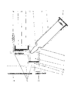
Figure 7 shows a schematic cross-sectional view of a further opening device
according
to the invention. An ampoule 61 made of a fragile material is arranged in the
opening
device. The ampoule 61 has an ampoule head 64 and an ampoule body 61 and is
filled
with a monomer liquid. The ampoule neck between the ampoule head 64 and the
ampoule body 61 comprises a predetermined breakage site 65 such that the
ampoule
head 64 is easy to break off the ampoule body 61.
The opening device comprises two plates 67 and a pestle 68 with an edge. The
plates
67 connected to tensioned compression springs 69 and a pestle 68 is connected
to a
tensioned compression spring 69. In this context, the plates 67 can be
interpreted to be
a mobile positioning aid 67 for the ampoule 61 and the ampoule head 64. The
pestle 68
can be interpreted to be a mobile opening facility 68. This separation into
positioning aid
67 and opening facility 68 may not be found, impeccably and without further
ado, in all
conceivable embodiments according to the invention. However, the underlying
principle
is obvious to a person skilled in the art, namely that the elastic energy
stores 69 can be
used to drive both the monomer liquid container 61 (and/or the positioning aid
67 with
the monomer liquid container 61 attached to it) and the opening facility 68
against each
other.
CA 02899539 2015-08-05
19
The springs 69 are kept in the tensioned position by means of a lock (not
shown) or by
means of three mutually independent locks (not shown). When the lock and/or
locks are
detached, the neck of the ampoule 61 is pushed onto the edge of the pestle 68
and the
pestle 68 is pushed against the neck of the ampoule 61. As a result, the
ampoule 61
breaks at the predetermined breakage site 65 and the ampoule 61 is thus being
opened.
The monomer liquid contained in the ampoule 61 leaks out (downwards in Figure
7) and
can be used to mix a PMMA bone cement. For this purpose, the springs 69 are
held in
position by a matching housing (not shown) and the plates 67 and the pestles
68 are
arranged such as to be mobile with respect to the housing and are simply
arrested by
means of the lock. A collecting trough (not shown) for collecting the leaking
monomer
liquid can be arranged below the ampoule 61. Preferably, the collecting trough
is
connected to a conduit means (not shown) that guides the monomer liquid to a
mixing
space (not shown) containing a cement powder.
The features of the invention disclosed in the preceding description and in
the claims,
figures, and exemplary embodiments, can be essential for the implementation of
the
various embodiments of the invention both alone and in any combination.
List of reference numbers
1 Glass ampoule / monomer liquid container
2 Vessel
3 Lid
4 Ampoule head
6 Bracketing
7 Space for collecting the ampoule head
8 Pestle / opening facility
9 Spring / elastic energy-storing element
12 Deformable wall
14 Frame
16 Safety pin/lock
CA 02899539 2015-08-05
18 Tube socket
20 Conduit / conduit means
22 Sieve/filter
23 Collecting trough
24 Base/foot part
26 Recess
31 Film pouch / monomer liquid container
34 Film pouch head
35 Film
36 Bracketing
37 Space in the film pouch head
38 Hello mandrel / opening facility
39 Spring / elastic energy-storing element
44 Housing
46 Lock
48 Tube socket
50 Hose / conduit means
56 Recess
58 Recess
61 Ampoule
64 Ampoule head
65 Predetermined breakage site
67 Plate / opening facility
68 Pestle with edge / opening facility
69 Spring