Note : Les descriptions sont présentées dans la langue officielle dans laquelle elles ont été soumises.
CA 02899618 2015-08-06
1
Handle for a door or window with two or three point latch
The present invention relates to doors or windows intended to furnish openings
formed in
the walls of rooms, in particular rooms on-board a boat.
In particular, the invention relates to a latching system for a door or
window, characterized
in that it comprises
a first snap stop member adapted to be arranged at a side edge of a leaf of
the door or
window, said first stop member comprising a pawl rotatable about an axis
perpendicular to
the plane defined by the leaf,
a second snap stop member adapted to be arranged at an upper or lower edge of
the
leaf, said second stop member comprising a pivot translatable in a vertical
direction, and
a handle rotatable so as to control the unlatching movement of said first and
second
stop members, said handle being adapted to be arranged at the side edge of the
leaf and being
rotatable about a horizontal axis parallel to the plane defined by the leaf,
and
a first and a second transmission mechanism for converting a rotation of the
handle
into a rotation of the pawl and a translation of the pivot, respectively.
Preferred embodiments of the invention are defined in the dependent claims
which form an
integral part of the present description.
Further characteristic features and advantages of the present invention will
become clear
from the following detailed description provided purely by way of a non-
limiting example,
with reference to the accompanying drawings in which:
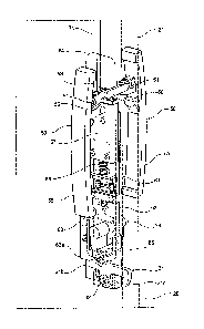
Figure 1 is a partial view of a door provided with a two-point latching system
according to the invention;
Figures 2 and 3 are perspective views of the actuating block of the latching
system
according to Figure 1, complete with and without the handles, respectively, in
the released
handle position.
Figure 4 shows an elevation view of the actuating block in the position shown
in
Figures 2 and 3;
CA 02899618 2015-08-06
2
Figures 5 and 6 are perspective views of the actuating block of the latching
system
according to Figure 1, complete with and without the handles, respectively, in
the raised
handle position;
Figure 7 shows an elevation view of the actuating block in the position shown
in
Figures 5 and 6;
Figure 8 is a partial view of a door provided with a three-point latching
system
according to the invention;
Figures 9 and 10 are a perspective view and elevation view, respectively, of
the
actuating block of the latching system according to Figure 8, without the
handles, in the
released handle position; and
Figures 11 and 12 are a perspective view and elevation view, respectively, of
the
actuating block of the latching system according to Figure 8, without the
handles, in the
raised handle position.
With reference to Figures 1 and 2, these show an example of a door or window,
denoted
overall by 1, realized in the form of a glazed door having a sliding leaf
adapted to be
mounted on a wall of a room in a boat.
The door or window 1 comprises a main frame 10 adapted to be mounted on the
aforementioned wall (not shown) so as to surround an opening foliated in said
wall, and a
leaf 20 mounted on said frame.
The leaf 20 comprises a pair of uprights, one of which, denoted by 21, is
shown in Figure 2,
and a pair of cross-pieces which interconnect these uprights. The leaf 20
therefore has two
side edges, one of which, denoted by 23, is shown in Figure 1, and upper and
lower edges
24, 25 (the lower edge is shown in Figure 8).
The upright 21 has a hollow cross-section, and in its interior is housed a two-
point latching
system according to the invention, shown more clearly in Figures 2 to 7.
The latching system of the door 1 comprises a first snap stop member 30
arranged at the side
CA 02899618 2015-08-06
3
edge 21 of the leaf 20 of the door or window. The first stop member 30
comprises a pawl 31
rotatable about an axis 33 perpendicular to the plane defined by the leaf 20
(that is, to the
plane of Figure 1) and adapted to engage with a striker element 35 positioned
on the main
frame 10 of the door or window, so as to lock the leaf 20 when the door is in
the closed
position.
The latching system further comprises a second snap stop member 40 arranged at
the upper
edge 24 of the leaf 20. The second stop member 40 comprises a pivot or pin 41
translatable
in a vertical direction and adapted to be inserted inside a seat (not shown)
positioned on the
main frame 10 of the door or window, so as to lock the leaf 20 when the door
is in the closed
position (or in other different locked positions, in the case where the leaf
is a sliding leaf
with the possibility of locking in several positions).
The latching system also comprises a handle 50 (shown in Figure 2) rotatable
so as to
control the releasing movement of the first and second stop members 30, 40.
The handle 50
is arranged at the side edge 23 of the leaf 20 and is rotatable about a
horizontal axis 51
parallel to the plane defined by the leaf 20 (see Figure 2). In particular, as
can be seen in
Figure 2, there are two handles 50 arranged on opposite sides of the leaf 20.
Each handle 50
is pivotably mounted on a projection 53 extending perpendicularly from a
fixing plate 54
(shown in broken lines in Figure 2) fixed to the upright 21.
In order to convert the rotation of the handles 50 into a rotation of the pawl
31 and into a
translation of the pivot 41, a first and a second transmission mechanism are
provided housed
inside the upright 21, said mechanisms being described below.
The handles 50 are coupled with the first and second transmission mechanisms
independently of each other. Therefore, if one of them is operated to release
the latching
system, the other one remains fixed in its original position (see Figure 5)
owing to an elastic
return element (not shown) associated with it.
Each handle 50 comprises a first and a second lever arm 55, 56; the first
lever arm 55 forms
CA 02899618 2015-08-06
4
a handgrip of the handle 50 and the second lever arm 56 forms an actuating tip
adapted to
engage with a follower element 57. As can be seen in Figure 2, the second
lever arms 56 of
the two handles 50 are arranged alongside each other so as to not to interfere
with each other
when one of the handles is raised.
The follower element 57 is mounted in a vertically slidable manner on a
support plate 58
fixed inside the upright 21. An elastic return element 59, in particular a
compression spring,
is arranged, in the sliding direction of the follower element 57, between the
follower element
57 and a bearing element 61 joined together with the support plate 58. With
raising of one
of the handles 50, the follower element 57 is pushed to translate downwards by
the actuating
tip 56 of the handle 50, against the action of the elastic return element 59.
The follower element 57 forms a component common to both the first and the
second
transmission mechanism.
As regards the first transmission mechanism, the follower element 57 comprises
an
extension 63 which, in the example shown, is formed by a bar which is fixed to
the follower
element 57 and extends from the opposite side with respect to the second stop
member 41.
The pawl 31 is formed by a rocker arm pivotably mounted on the support plate
58 and
having a pawl arm 31a, adapted to engage with the striker element 35
positioned on the main
frame 10 of the door or window, and en engaging arm 31b, adapted to be engaged
by a tip
63a of the extension 63 of the follower element 57. An elastic return element
65, which, in
the example shown, consists of a torsion spring, is associated with the
engaging arm 3 lb of
the pawl 31.
When the door is brought into the closed position, the pawl 31 engages with a
front part of
the corresponding striker element 35 on the main frame 10, rising against the
action of the
elastic return element 65 until it snaps over the front part of the striker
element 35.
In order to release the pawl the handles 50 are operated. With raising of one
of the handles
CA 02899618 2015-08-06
50 the follower element 57, and along with it the extension 63, is in fact
pushed to translate
downwards by the actuating tip 56 of the handle 50. The tip 63a of this
extension thus
engages with the engaging arm 31b of the pawl 31 and pushes the pawl to rotate
against the
action of the elastic return element 65. The pawl arm 31a is therefore raised
(see Figures 5 to
7), disengaging the striker element 35.
The first transmission mechanism for operation of the pawl 31 therefore
comprises the tip 56
of the handle 50, the follower element 57, the tip 63a of the extension 63 of
the follower
element 57 and the engaging arm 31b of the pawl 31 of the first stop member
30.
As regards the second transmission mechanism, the end of a rod 71 is fixed to
the follower
element 57, its other end being connected, by means of an elastic return
element 73 (in the
example a compression spring) to the pivot 41 of the second snap stop member
40.
When the door is brought into the closed position (or another locked
position), the pivot 41
is located in correspondence of the respective seat on the main frame 10 and
therefore, as a
result of the elastic return element 73, snap-engages inside this seat.
In order to release the pivot 41, the handles 50 are operated. With raising of
one of the
handles 50 the follower element 57, and along with it the rod 71, is in fact
pushed to
translate downwards by the actuating tip 56 of the handle 50. The pivot 41 of
the second
snap stop member 40 is therefore lowered, freeing the respective seat on the
main frame 10.
The latching system comprises, finally, a lock 75 which can be operated in a
per se
conventional manner so as to lock the latching system, acting for example on
the extension
63 of the follower element 57.
With reference to Figures 8 to 12 these show a second example of embodiment of
a latching
system according to the invention. The same reference numbers have been
assigned to
elements corresponding to those of the embodiment; these elements will not be
further
described.
CA 02899618 2015-08-06
6
The embodiment shown in Figures 8 to 12 differs from the preceding embodiment
in that it
consists of a three-point latching system.
In particular, in said system a third snap stop member 80 is arranged at the
lower edge 25 of
the leaf 20. The third stop member 80 comprises a pivot or pin 81 translatable
in a vertical
direction and adapted to be inserted inside a seat (not shown) positioned on
the main frame
of the door or window, so as to lock the leaf 20 when the door is in the
closed position (or
in other different locked positions, in the case where the leaf is a sliding
leaf with the
possibility of locking in several positions).
The movement of the pivot 81 of the third snap stop member 80 is performed by
means of a
third transmission mechanism adapted to convert the rotation of the handle 50
into a
translation of the pivot 81. The transmission of the movement from the handle
50 to the
pivot 81 of the third stop member takes place starting from the follower
element 57, together
with actuation of the first stop member 30 and the second stop member 40.
The third mechanism comprises further extension elements 82, 83 which are
rigidly
connected to the extension 63 of the follower element 57. An elastic return
element 85,
which in the example is a compression spring, is arranged between the more
distal extension
element 83 and a bearing part 84 of the support plate 58. The more distal
extension element
83 is further connected to a linkage 86 adapted to reverse the direction of
movement of the
pivot 81 of the third stop member 80 with respect to that of the follower
element 57. The
linkage 86 comprises a first rod 86a, a rocker arm 86b and a second rod 86c.
The first rod
86a is hinged at one end to the more distal extension element 83 and at the
other end to one
end of the rocker arm 86, which is pivotably mounted on the support plate 58
at an
intermediate point thereof. The other end of the rocker arm 86b is hinged to
one end of the
second rod 86c. The other end of the second rod 86c is hinged to a connection
element 87,
which is rigidly connected to one end of a bar 88. The pivot 81 of the third
stop member 80
is fixed to the other end of the bar 88.
CA 02899618 2015-08-06
7
When the door is brought into the closed position (or another locked
position), the pivot 81
is located correspondence to the respective seat on the main frame 10 and
therefore, as a
result of the elastic return element 85, snap-engages inside this seat.
In order to release the pivot 41, the handles 50 are operated. With raising of
one of the
handles 50 the follower element 57, and along with it the extension 63 and the
extension
elements 83, 83, is in fact pushed to translate downwards by the actuating tip
56 of the
handle 50. The linkage 86 therefore causes the upwards movement of the bar 88.
The pivot
81 of the third snap stop member 80 is therefore raised (against the action of
the elastic
return element 85), freeing the respective seat on the main frame 10.