Note : Les descriptions sont présentées dans la langue officielle dans laquelle elles ont été soumises.
CA 02899749 2015-07-29
WO 2014/118568 PCT/GB2014/050283
1
SECURITY DEVICES AND METHODS OF MANUFACTURE THEREOF
This invention relates to security devices, suitable for establishing the
authenticity of objects of value, particularly security documents, and their
methods of manufacture. In particular, the invention relates to security
devices
incorporating optically variable effect generating relief structures such as
holograms and diffraction gratings.
Optically variable effect generating relief structures such as holograms and
diffraction gratings have been used widely over the last few years to impart
security to documents of value such as banknotes, credit cards, passports and
the like. Conventionally, the structure is provided on a transfer foil and
then hot
stamped from the transfer foil onto the final document substrate. An early
example of this approach is described in US-A-4728377.
More recently, such structures have been used in combination with transparent
window features formed in the document substrate to allow the optically
variable
effect to be viewed through the document. The window may take the form of an
aperture through one or more layers of the document substrate or may comprise
an optically transparent region of the document substrate. An example of an
optically variable effect generating relief structure located in a window
region
formed as an aperture in a document is given in CA-C-2163528. An example of
an optically variable effect generating relief structure located in a window
region
formed as a transparent region of a document (here, a polymer banknote) is
given in WO-A-2008/031170.
Placing a security device in a window has the advantage that the device can be
viewed from both sides of the document. As such it is desirable that a secure
visual effect is exhibited by both sides of the security device, in order to
increase
the difficulty of counterfeiting. Examples of devices in which both sides
exhibit a
secure effect are disclosed in CA-C-2163528, US-A-2005/0104364, US-A-
2007/0114787, CA-A-2717775 and CA-A-2611195. However, there is an ever-
present need to improve the security level of such devices in order to stay
ahead
of would-be counterfeiters.
CA 02899749 2015-07-29
WO 2014/118568 PCT/GB2014/050283
2
In accordance with the present invention, a security device is provided
comprising a first transparent layer having an optically variable effect
generating
relief structure formed in a surface thereof; a reflection enhancing layer
extending over the relief structure and following the contour of the relief;
and a
second transparent layer extending over the reflection enhancing layer, the
lateral extent of the second transparent layer being less than the whole area
of
the security device and corresponding to the lateral extent of the reflection
enhancing layer, wherein the first and/or second transparent layer comprises
one or more optically effective substances such that the appearance of the
optically variable effect generated by the relief structure is different when
viewed
through the first transparent layer compared with when viewed through the
second transparent layer, at least under illumination at a wavelength at which
at
least one of the optically effective substance(s) is visible.
By arranging the reflection enhancing layer and the second transparent layer
to
have the same lateral extent which is less than the whole area of the device
(i.e.
so that the device also includes at least one region where the reflection
enhancing material and second transparent layer are absent, which is
preferably
transparent - for instance the lateral extent of the reflection enhancing
layer and
the second transparent layer may be less than the lateral extent of the first
transparent layer), the device appears to present two different secure visual
effects (one visible from each side of the device), in exact register with one
another. When viewed through the first transparent layer, the colour of the
optically variable effect is dictated by that of the first transparent layer
(if any), in
combination with that of the reflection enhancing layer. The second
transparent
layer is concealed exactly by the reflection enhancing layer and does not
contribute to the appearance. When the device is viewed from the opposite
side, through the second transparent layer, the colour of the optically
variable
effect appears different, being due to the combination of the second
transparent
layer with the reflection enhancing layer. From
this viewpoint, the first
transparent layer does not contribute to the appearance of the optically
variable
effect, being concealed again by the reflection enhancing layer (although the
first
transparent layer may be visible in laterally offset regions, e.g. surrounding
the
CA 02899749 2015-07-29
WO 2014/118568 PCT/GB2014/050283
3
optically variable region). Thus the impression of two different yet precisely
registered devices can be achieved through the provision of a single device in
a
manner which is very difficult to imitate.
It should be noted that the term "colour" used herein should be taken to
encompass optical effects which are invisible under ambient illumination
conditions (i.e. visible illumination wavelengths), and become apparent only
under illumination at specific non-visible wavelengths such as UV or IR, as
well
as colours which are visible in visible light. In
addition the term "colour"
encompasses all hues and tones which are visible, including black, grey and
silver as well as chromacities such as red, blue, green etc.
The term "transparent" means that the material in question is substantially
clear,
with low optical scattering ¨ i.e. items on one side of the material can be
seen
through it, from the other ¨ but not necessarily colourless. For instance, a
transparent material may carry a coloured tint.
Each of the first and second transparent layers could comprise optically
effective
substances. However, in preferred embodiments, only one of the first and
second transparent layers comprises an optically effective substance, the
other
of the first and second transparent layers appearing colourless under
illumination
of any wavelength. In
particular it is advantageous if only the second
transparent layer comprises an optically effective substance. Should the first
transparent layer be visible from the second side of the device (e.g. in
regions of
the device laterally offset from the reflection enhancing layer), the
colourless
appearance of the first transparent layer will not detract from or compete
with the
colour of the second transparent layer. The optically variable effect may
appear
invisibly "suspended" within the device from both sides.
However, in other preferred embodiments, each of the first and second
transparent layers comprise different optically effective substances. This may
encompass both transparent layers having one or more common optically
effective substances, but one or other of the layers will contain at least one
optically effective substance which the other does not. For instance, both
CA 02899749 2015-07-29
WO 2014/118568 PCT/GB2014/050283
4
transparent layers may comprise the same UV-responsive substance, whilst only
the second transparent layer is provided with a visible colourant.
In particularly preferred embodiments, the first and/or second transparent
layers
comprise one or more optically effective substance(s) which impart a coloured
tint to the respective layer, which colour is visible under illumination at
visible
wavelengths. In this way the two different appearances of the device can be
checked for without the need for any special illumination. In some preferred
cases, the first transparent layer has a visible coloured tint of a first
colour, and
the second transparent layer has a visible coloured tint of a second,
different
colour. Advantageously the two colours contrast strongly with one another,
e.g.
yellow and blue.
In further preferred embodiments, the first and/or second transparent layers
comprise one or more optically effective substance(s) which are visible only
under illumination at selected wavelengths outside the visible spectrum,
preferably ultraviolet or infrared wavelengths. This provides for a more
covert
security feature which can be checked by eye or by machine.
In still further preferred embodiments, the first and/or second transparent
layers
comprise one or more optically effective substance(s) which undergo a change
in appearance in response to changes in one or more of temperature, pressure,
strain or electrical potential. For example, thermochromic, piezochromic or
electrochromic substances could be used. In each case the varying appearance
of the substance may be visible within or outside the visible spectrum, and
may
change from one to the other.
Preferably, the optically effective substance(s) comprise dyes and/or
pigments.
Dyes are preferred in order to preserve the optical clarity of the layer(s).
The optically effective substance(s) could be provided uniformly across the
respective layer. However in preferred embodiments the complexity of the
security device may be further enhanced by arranging one or more of the
substances to appear as a pattern. Thus, preferably, the second transparent
CA 02899749 2015-07-29
WO 2014/118568 PCT/GB2014/050283
layer comprises at least two transparent materials arranged in a pattern, at
least
one of the transparent materials comprising an optically effective substance
such
that the appearance of the optically variable effect generated by the relief
structure is modified by the pattern when viewed through the second
transparent
5 layer, at least under illumination at a wavelength at which the optically
effective
substance is visible. For example, the first material, containing a colourant
or
similar, could be laid down in the shape of a symbol or letter, and the second
material (which may contain a different colourant or may be colourless) may be
laid down in register surrounding the first material to complete the second
transparent layer. Advantageously, the at least two transparent materials each
comprise a different optically variable substance, which can be distinguished
from one another by the human eye or by machine.
The second transparent layer preferably comprises one or more polymeric
materials, such as vinyl resins, most preferably having one or more optically
effective substance(s) dispersed therein as discussed above.
Particularly
advantageously, the second transparent layer comprises a resist material which
is resistant to etchant suitable for removing material of the reflective layer
from
the device. This enables the security element to be manufactured using the
particularly beneficial techniques discussed below. For example, where the
reflective layer is formed of a metal, the second transparent layer is
preferably
resistant to an etchant able to dissolve the metal, e.g. sodium hydroxide
which is
able to etch aluminium. If the second transparent layer is made up of two or
more transparent materials, preferably both provide substantially the same
etch
resistant properties.
The second transparent layer preferably is of sufficient thickness so as to
protect
the reflective layer during etching and hence in advantageous embodiments has
a thickness of between 0.5 and 5 microns, more preferably between 1 and 2
microns.
Advantageously, the second transparent layer is a printed layer, preferably
formed by gravure printing, flexographic printing or slotted die printing. In
this
way, the second transparent layer can be laid down in any desirable form
CA 02899749 2015-07-29
WO 2014/118568 PCT/GB2014/050283
6
through control of the printing apparatus using well-known printing
techniques.
Gravure printing is most preferred due to the high resolution that is
achievable.
The lateral extent of the reflection enhancing layer and second transparent
layer
may or may not be related to that of the relief structure, which may itself
extend
over the whole device or not. For instance, whilst in some embodiments the
lateral extent of the reflection enhancing layer and second transparent layer
matches that of the relief structure, in more preferred embodiments the two do
not match, e.g. their perimeters do not confirm to one another to within 100
microns. In other words, either at least a portion of the reflection enhancing
layer
(and second transparent layer) is located outside the relief structure, or the
reflection enhancing layer (and second transparent layer) is absent over at
least
a portion of the relief structure, or both. In particularly preferred
embodiments,
the reflection enhancing layer (and second transparent layer) extends beyond
the periphery of the relief structure in at least one, preferably in all,
directions,
e.g. by at least 100 microns. This is advantageous since the replay exhibited
by
the relief structure may appear on a plane in front or behind that of the
device
itself, in which case upon tilting, the replayed image will move relative to
the
device. By continuing the reflection enhancing layer beyond the relief this
enables the full image to be viewed against a reflective background during
tilting.
The inclusion of a substantially flat reflective region in this way also acts
as an
additional security feature since it will be bright and eye-catching, thereby
further
increasing the security level of the device.
In preferred embodiments, the lateral extent of the reflection enhancing layer
and second transparent layer defines a secure or decorative shape or pattern,
preferably a fine line pattern, or an item of information, preferably a
number,
letter, alphanumerical text, a symbol or a graphic. Where the second
transparent layer is used as an etch resist, this can be achieved through
laying
down the second transparent layer in the desired form (e.g. by printing).
Preferably, the second transparent layer is registered to the relief
structure. That
is, the second transparent layer has been laid down in register with the
relief
structure having the result that the two items will be in substantially the
same
CA 02899749 2015-07-29
WO 2014/118568 PCT/GB2014/050283
7
relative position to one another on each security device made to the same
design (e.g. a series of such devices). This
increases the difficulty of
counterfeiting since a document displaying a different alignment between the
optically variable effect and the lateral extent of the reflection enhancing
layer
and second transparent layer (which will be the same) will be readily
distinguished from genuine devices.
As noted above, the reflection enhancing layer and second transparent layer
could define any shape or pattern and in preferred examples the reflection
enhancing layer (and the second transparent layer, since this will have the
same
lateral extent) includes at least two laterally offset regions which are
visibly
discontinuous. This increases the complexity of the device and hence the
difficulty of forgery.
In many preferred embodiments, the reflection enhancing layer is substantially
opaque such that the second transparent layer cannot be seen therethrough.
However, in other embodiments, the reflection enhancing layer may be semi-
transparent, achieved for example through the use of an extremely thin layer
of
reflection enhancing material. In this case the second transparent layer may
be
apparent through the reflection enhancing material when the device is viewed
in
transmitted light. However, in all cases the second transparent layer should
be
substantially hidden by the reflection enhancing material when the device is
viewed in reflection through the first transparent layer.
By arranging the reflection enhancing layer to be semi-transparent in this
way,
additional effects can be achieved. For example, the apparent colour of the
security device viewed from one side may be different depending on whether the
device is being viewed in reflected or transmitted light. When viewed in
reflection through the first transparent layer, the light reflected by the
reflection
enhancing layer dominates the appearance of the device and effectively
conceals the colour of the second transparent layer behind it such that the
device appears to have the colour of the reflection enhancing layer (modified
by
any additional colour in the first transparent layer). When viewed in
transmission
from the same side, the different colour of the second transparent layer will
be
CA 02899749 2015-07-29
WO 2014/118568 PCT/GB2014/050283
8
visible through the reflection enhancing layer, thereby appearing to change
the
colour of the device. If both the first and second transparent layers are
provided
with a (different) optically effective substance, when viewed in transmission
these will combine with one another to produce a third colour which is
different
again.
The reflection enhancing layer may be formed as a continuous layer in each
region of the shape or pattern to be defined. In other embodiments, the
reflection enhancing layer may comprise a screened working of discontinuous
elements. Typically such elements would be too small to be individually
discerned by the naked eye. The second transparent layer would by definition
be arranged according to the same screen. In this way the optically variable
effect may appear semi-transparent from both sides of the device, in
reflection
and/or transmission. However it should be noted that this configuration will
not
lead to the additional colour effect described above unless the reflection
enhancing layer is also formed sufficiently thinly so as to be intrinsically
semi-
transparent.
In particularly preferred implementations, the reflection enhancing layer
comprises one or more metals or alloys thereof, preferably copper, aluminium,
nickel, chrome or any alloys thereof (e.g. nickel-chrome alloys). Metal
reflective
layers, preferably laid down by vacuum deposition (encompassing sputtering,
resistive boat evaporation or electron beam evaporation for example), or by
chemical vapour deposition, achieve highly specular reflection and hence a
very
bright replay of the optically variable effect. In other
advantageous
implementations, the reflection enhancing layer could comprise any of:
= an optical interference thin film structure;
= a layer containing metallic particles, optically variable particles or
optically variable magnetic particles;
= a photonic crystal layer; or
= a liquid crystal layer.
Such materials can be used to provide the device with additional visual
effects,
e.g. exhibiting different colours at different viewing angles ("colour
shift"), which
will appear superimposed on the visual effect produced by the relief
structure.
CA 02899749 2015-07-29
WO 2014/118568 PCT/GB2014/050283
9
The reflection enhancing layer follows the contour of the relief structure on
both
of its surfaces such that the optically variable effect is exhibited by both
sides. In
order to achieve this, the reflection enhancing layer preferably has a
thickness
less than the profile depth of the relief structure. For example, typical
diffractive
relief structures such as holograms may have profile depths of the order of 50
to
500 nm, more often between 80 and 150 nm. In contrast, the reflection
enhancing layer preferably has a thickness between 5 and 100 nm. For
instance, a layer of aluminium having a thickness of around 15 to 30 nm is
suitable for providing a virtually fully opaque reflective layer. A layer
of
aluminium with a thickness around 5 to 10 nm can be used to provide a semi-
transparent reflection enhancing layer.
Preferably, the optically variable effect generating relief structure
comprises a
diffractive device such as a hologram, a diffraction grating or a KinegramTM,
or a
non-diffractive micro-optical structure such as a prismatic structure. Non-
diffractive optical structures typically are of much larger dimensions to
those
mentioned above in relation to holographic devices, with profile depths of
between 2 and 50 microns. Examples of prismatic structures suitable for the
current invention include, but are not limited to, a series of parallel linear
prisms
with planar facets arranged to form a grooved surface, a ruled array of
tetrahedra, an array of square pyramids, an array of corner-cube structures,
and
an array of hexagonal-faced corner-cubes. A second preferred type of micro-
optical structure is one which functions as a microlens including those that
refract light at a suitably curved surface of a homogenous material such as
piano-convex lenslets, double convex lenslets, piano-concave lenslets, and
double concave lenslets. Other
suitable micro-optical structures include
geometric shapes based on domes, hemispheres, hexagons, squares, cones,
stepped structures, cubes, sawtooth structures, faceted structures or
combinations thereof.
The first transparent layer may take a number of forms depending in part on
how
the security device is to be incorporated or applied to an object of value. In
some
preferred examples, the first transparent layer comprises a thermoplastic
CA 02899749 2015-07-29
WO 2014/118568 PCT/GB2014/050283
polymer ¨ for instance forming part of a substrate web of e.g. polyester, or
an
embossing lacquer carried thereon, which may act as a support for the security
device as a whole or even for a security document of which the security device
will ultimately form part. In such cases, the relief structure may be formed
in the
5 surface of the thermoplastic by conventional embossing techniques using
heat
and pressure, for example. In other preferred implementations, the transparent
layer may comprise a curable polymer, preferably a UV-curable polymer. For
instance, the relief could be cast-cured into a coating of UV-curable resin.
In still
further embodiments, the first transparent layer could comprise a curable
10 thermoplastic polymer (i.e. a thermoplastic polymer with a curing agent
added)
such that, after embossing, the relief can be fixed by curing.
As noted above, in some embodiments the first transparent layer forms an
integral part of a substrate, preferably a security document substrate or a
security article substrate. For instance, the relief structure may be embossed
directly into a transparent layer making up the substrate of a polymer (or
polymer
/ paper composite) banknote, or forming the substrate of a security article
such
as a security thread or foil which is later to be incorporated into or applied
to a
security document or other object of value. In other preferred embodiments,
the
first transparent layer is disposed on a substrate, preferably a security
document
substrate or a security article substrate. This is the case for example where
the
relief is formed in a coating or other layer carried by the substrate, e.g. a
cast-
cured relief.
If the device is to be formed independently of the security document or other
object of value to which it is to be applied, the device preferably further
comprises one or more transparent adhesive layers. These may form the
outermost layer of the device on either or both sides. By selecting a
transparent
adhesive, the appearance of the optically variable effect is not diminished.
The invention further provides a security article comprising a security device
as
described above, the security article preferably comprising a transfer band or
sheet, a security thread, a foil, a patch, a label or a strip. Also provided
is a
security document comprising a security device as described above or a
security
CA 02899749 2015-07-29
WO 2014/118568 PCT/GB2014/050283
11
article as described above, the security document preferably comprising a
banknote, cheque, identification document, certificate, share, visa, passport,
driver's licence, bank card, or ID card. Preferably the security device is
arranged
in a window or half-window region of the security document.
Further provided is a method of manufacturing a security device, comprising:
forming an optically variable effect generating relief structure in a surface
of a first transparent layer;
applying a reflection enhancing material over the relief structure to form a
reflection enhancing layer which follows the contour of the relief;
applying a second transparent layer over the reflection enhancing
material; and
removing the reflection enhancing material from regions of the device in
which the reflection enhancing material is not covered by the second
transparent
layer, such that the lateral extent of the reflection enhancing material
corresponds to that of the second transparent layer;
wherein the first and/or second transparent layer comprises an optically
effective substance such that the appearance of the optically variable effect
generated by the relief structure is different when viewed through the first
transparent layer compared with when viewed through the second transparent
layer, at least under illumination at a wavelength at which the optically
effective
substance is visible.
By using the second transparent layer to define those regions of the
reflection
enhancing material which are subsequently removed, the lateral extent of the
two layers can be accurately matched. As described above, this results in the
device exhibiting an optically variable effect on both sides, with a different
appearance due to the optically effective substance(s) in the first and/or
second
transparent layers. This presents the appearance of two different security
devices in exact register, achieving a striking visual effect which is
extremely
hard to counterfeit.
CA 02899749 2015-07-29
WO 2014/118568 PCT/GB2014/050283
12
The optically effective substance(s) can take any of the forms mentioned
above,
and be disposed in the first and/or second transparent layers in the manners
already described.
Any forming technique could be used to provide the relief in the first
transparent
layer. Advantageously, the optically variable effect generating relief
structure is
formed in the surface of the first transparent layer by embossing or cast-
curing,
preferably UV cast-curing.
Preferably, the reflection enhancing layer is applied in a continuous layer
over
the relief structure. However, the reflection enhancing layer could be applied
in
a patterned manner prior to the deposition of the second transparent layer if
desired, e.g. through the use of a repellent coating applied to selected
regions of
the relief before application of the reflection enhancing material.
The reflection enhancing layer could be applied by any appropriate technique
for
the material in use, but in preferred examples is applied by vacuum deposition
which has been found to achieve particularly good conformity of the reflective
material to the relief. In alternative implementations, the reflection
enhancing
layer could be applied by sputtering or chemical vapour deposition, or
printing if
for example a metallic ink is used. Any of the properties and characteristics
of
the reflection enhancing layer described above could be implemented.
Preferably, the second transparent layer is applied by printing, most
preferably
by gravure printing, flexographic printing or slotted die printing.
Printing
techniques enable precise control of the shape or pattern in which the second
transparent layer is laid down. However, in other embodiments, the second
transparent layer could be applied by coating, deposition or transfer
techniques.
In particularly preferred embodiments, the second transparent layer is applied
in
register with the relief structure. This can be achieved for example by
performing both operations as part of the same, in-line manufacturing process.
Any of the properties and characteristics of the second transparent layer
described above may be implemented in the method. For instance, in some
CA 02899749 2015-07-29
WO 2014/118568 PCT/GB2014/050283
13
embodiments, the second transparent layer may preferably be applied so as to
define at least two laterally offset regions which are visibly discontinuous,
leading to the same visible discontinuities in the reflection enhancing layer.
In
further embodiments, the second transparent layer may be applied so as to
define a screened working of discontinuous elements.
The reflection enhancing material could be removed using any technique which
utilises the second transparent layer to define the regions to be removed. In
particularly preferred embodiments, the reflection enhancing material is
removed
by etching, the second transparent layer acting as an etch resist. For
example,
where the reflection enhancing material is aluminium, the etchant may be
sodium hydroxide. In other examples, the reflection enhancing material could
be
removed by other means such as laser ablation or ion etching.
Any of the other features of the security device described above may be
incorporated through appropriate adaptation of the method.
Where the security device is formed as a security article, the security
article
including the device may be incorporated into or applied to a security
document
by any conventional technique, such as hot stamping, cold adhesion,
laminating,
incorporation into paper-making process, etc. The security device is
preferably
arranged to overlap at least partially and preferably fully with a window
region of
the document, e.g. an aperture or a transparent portion, which may be formed
before or after incorporation of the security device.
Preferred embodiments of security devices and manufacturing methods in
accordance with the present invention will now be discussed and contrasted
with
comparative examples, with reference to the accompanying Figures, in which:-
Figure 1 schematically depicts a first comparative example of a security
article
incorporating a security device;
Figure 2 depicts the security device of Figure 1 applied to an exemplary
security
document, together with schematic views of (i) the appearance of the security
CA 02899749 2015-07-29
WO 2014/118568 PCT/GB2014/050283
14
device viewed by observer A; and (ii) the appearance of the security device
viewed by observed 13;
Figures 3a and 3b depict two further comparative examples of security articles
incorporating security devices;
Figure 4 shows the security device of Figure 3a applied to an exemplary
security
document, together with schematic views of (i) the appearance of the security
device viewed by observer A; and (ii) the appearance of the security device
viewed by observer B;
Figure 5 depicts a first embodiment of the security device in accordance with
the
present invention applied to an exemplary security document, together with
schematic views of (i) the appearance of the security device viewed by
observer
A; and (ii) the appearance of the security device viewed by observer B;
Figure 6 is a flow diagram demonstrating selected steps in an exemplary method
of manufacturing a security device in accordance with the present invention.
Figures 7 a to e depict a second embodiment of a security device in accordance
with the present invention at various stages of manufacture;
Figure 8 shows exemplary apparatus suitable for carrying out a method of
manufacturing in accordance with the present invention;
Figure 9 depicts a third embodiment of a security device in accordance with
the
present invention;
Figure 10 depicts a fourth embodiment of a security device in accordance with
the present invention;
Figure 11 depicts a fifth embodiment of a security device in accordance with
the
present invention;
Figure 12 depicts a sixth embodiment of a security device in accordance with
the
present invention;
Figures 13a and 13b depict an exemplary security document in accordance with
the present invention, Figure 13b showing a cross-section along the line XX'
in
Figure 13a,
Figures 14a and 14b depict a further exemplary security document incorporating
a security device in accordance with the present invention, Figure 14b being a
cross-section along line XX' in Figure 14a,
Figures 15a, 15b and 15c depict a further exemplary security document
incorporating a security device in accordance with the present invention,
Figures
CA 02899749 2015-07-29
WO 2014/118568 PCT/GB2014/050283
15b and 15c depicting alternative cross-sections of the security document
taken
along line XX' in Figure 15a,
Figures 16a, 16b and 16c depict another exemplary security document
incorporating a security device in accordance with the present invention,
Figures
5 16a and 16b showing front and reverse views of the document (flipped
about its
short edge), and Figure 16c being a cross section along line XX' in Figures
16a
and 16b, and
Figures 17a, 17b and 17c depict a further exemplary security document
incorporating a security device in accordance with the present invention,
Figure
10 17a showing a left portion of the document viewed from the front side,
Figure
17b showing a right portion of the document viewed from the rear side (the
document having been flipped about its short edge), and Figure 17c being a
cross section along line XX' in Figures 17a and 17b.
15 The description below will focus on examples of security devices having
optically
variable effect generating relief structures in the form of holograms. By this
we
mean the relief is a structure which generates graphical images by the
mechanism of diffraction of light. However, more generally the term "optically
variable effect" means that an appearance is generated which varies depending
on the viewing angle. Other examples of optically variable effects which might
be implemented through the described relief structures include diffraction
gratings, KinegramsTM and prismatic effects, as mentioned above.
Figure 1 shows a security article 1 according to a first comparative example.
Here the security article 1 may comprise for example a transfer foil, security
thread, patch or similar which includes a security device 10 carried on a
support
layer 2. Typically, the support layer 2 acts as a release sheet or strip from
which
the device 10 is detached upon application to a security document, in which
case the support layer 2 can take any convenient form such as a (opaque,
translucent or transparent) polymer or paper web. A release layer (not shown)
may be provided between the support layer 2 and security device 10 to assist
in
the detachment of the security device 10 from the support layer 2 upon
application of the device to a security document. For example, where the
CA 02899749 2015-07-29
WO 2014/118568 PCT/GB2014/050283
16
transfer is to take place by hot stamping, the relief layer may comprise a
layer of
wax or similar.
The security device 10 comprises a transparent layer 3 into which a
holographic
(or other optically variable) relief structure 4 is formed. It should be noted
that
the transparent layer 3 may in practice be formed of multiple layers laminated
to
one another, and this applies to all "layers" mentioned throughout this
disclosure.
The transparent layer 3 can be formed of any suitable transparent material in
which a relief structure 4 can be formed, for example a conventional embossing
lacquer such as a thermoplastic polymer or a radiation curable resin. The
transparent layer 3 includes a colorant such as a suitable dye which imparts a
tint to the layer 3. The tint may or may not be visible to the human eye under
illumination at visible wavelengths. For example, the colorant could be
invisible
unless irradiated with selected wavelengths outside the visible spectrum, such
as UV or IR, and could be phosphorescent, fluorescent or luminescent.
However, in the most preferred examples, the colorant is visible under ambient
lighting conditions in order that the colour effect is readily apparent
without the
need for specialist equipment.
The relief structure 4 (shown in Figures 1 to 4 schematically as a dashed
line) is
formed into the layer 3 using an appropriate conventional technique such as
embossing under the combined action of heat and pressure, or cast curing, in
which the layer 3 is coated as a relatively fluid resin onto the support layer
2 and
a shaped die applied to the fluid resin having the desired relief shape. The
resin
flows to accommodate the die thereby taking on the desired relief shape and is
simultaneously or subsequently hardened, e.g. by curing with radiation such as
UV. Where the relief 4 is formed by cast curing, the layer 3 typically
comprises a
single homogenous film of resin. However, where the relief 4 is embossed, the
layer 3 more typically comprises multiple layers including at least a
protective
coating layer (commonly termed a "scuff' layer) which will cover the hologram
in
use and an embossing layer which is usually of a material which is
mechanically
softer and/or of lower glass transition temperature than the protective layer.
An
intermediate layer may also be included. The colorant could be located in any
of
CA 02899749 2015-07-29
WO 2014/118568 PCT/GB2014/050283
17
the multiple layers within layer 3, but most preferably is located in the
protective
coating and/or intermediate layer (if provided).
Following the formation of the relief structure 4, a reflection enhancing
layer 5
such as a metal is applied, preferably by vacuum metallisation. The reflection
enhancing layer 5 conforms to the relief structure 4, on both sides. As shown
in
the Figures, the metallisation covers the full area of the device.
Finally, in this example an optically clear adhesive 6 is applied over the
reflection
enhancing layer 5 to allow for easy adhesion of the device 10 to a document
substrate. However, in other examples an adhesive layer 6 could be provided
on the opposite side of the device (between layer 3 and support layer 2), on
both
sides of the device, or omitted entirely, e.g. if the security device is to be
incorporated into a document during the paper-making process, or if adhesive
is
provided on the document's surface itself.
Figure 2 shows the security device 10 now removed from security article 1 and
applied to security document 15 in the region of window 16. Here, the security
document is of conventional paper construction, having an aperture formed
through the document substrate to define the window 16. The security device 10
is arranged to extend across the window 16 and onto the surrounding portions
of
the document substrate 15 to allow for adhesion between the document and the
device. In other cases, the document could include a transparent material in
at
least one region forming a window 16, as will be described further in later
embodiments.
The security device 10 is visible from both sides of the security document 15
as
illustrated by observers A and B. From the location of observer A, the
optically
variable effect generated by relief structure 4 (e.g. a holographic image) in
combination with reflection enhancing layer 5 is visible, as denoted in Figure
2 (i)
by the symbol labelled H. The optically variable effect is viewed through the
coloured transparent layer 3 and hence the device as a whole including the
optically variable effect appears tinted with the colour of layer 3. From the
opposite side of the security document 15, observer B sees the same optically
CA 02899749 2015-07-29
WO 2014/118568 PCT/GB2014/050283
18
variable effect H, as shown in Figure 2 (ii) although the content of the
hologram
will appear reversed (i.e. a mirror image of that seen from the position of
observer A) due to the fact that the reverse side of relief 4 is being viewed.
However, the colour of the optically variable effect and the device as a whole
will
appear different from that seen in position A since it will be determined
solely by
the colour of reflection enhancing layer 5 (assuming that the clear adhesive
layer
6 is colourless). Thus, two different optically variable appearances can be
observed from the two sides of the device. However, since each of the two
optically variable appearances occupies the entire window area 16, the
relationship between the two effects is not particularly distinct and the
overall
effect could be imitated through the provision of two different holographic
devices of the appropriate colours on the two opposite sides of the document
with little difficulty.
Figures 3a and 3b show further comparative examples in which two different
optically variable appearances are achieved by providing a coloured print on
one
side of the reflection enhancing layer in a device. Generally, the reference
numbers used in Figures 3a and 3b correspond to those used in Figure 1 and
their respective components can be formed in the same way as previously
described. However, in this case, the transparent layer 3 into which relief
structure 4 is formed need not include a colorant (although it may if
desired).
After applying the reflection enhancing layer 5 (e.g. by vacuum
metallisation), a
coloured print 7 is applied by conventional printing techniques. The coloured
print 7 may cover the full area of the device, or define a continuous shape as
shown in Figure 3a, or take the form of indicia such as letters, numbers,
symbols
or graphics, as shown in Figure 3b.
Figure 4 depicts the device of Figure 3a applied to an exemplary security
document 15 using any of the same techniques mentioned above. Figure 4.(i)
depicts the appearance of the device from the position of observer A and here
the hologram H is seen having the colour of the reflection enhancing layer 5
(e.g.
silver). From the opposite side, observer B sees the same hologram H
(reversed in direction) but now possessing the coloured tint of print layer 7,
which in this case defines a star shape contained within the bounds of the
(oval)
CA 02899749 2015-07-29
WO 2014/118568 PCT/GB2014/050283
19
device. Outside the star shape, the original colour of the reflection
enhancing
layer 5 will be visible and the optically variable effect will continue. This
too is
relatively straightforward for a determined counterfeiter to imitate, e.g.
through
the use of two holograms and appropriate overprinting.
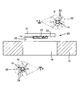
Figure 5 depicts a security device 20 in accordance with a first embodiment of
the invention, applied to an exemplary security document 15 in the region of a
window 16. In this case, window 16 is constituted by a transparent portion of
the
document 15 with the security device 20 being applied directly thereto.
However, the security device 20 could be applied across an aperture in the
same way as previously described.
The security device 20 comprises a first transparent layer 21 carrying an
optically variable effect generating relief structure 22 formed in its
surface. In the
Figure the relief structure 22 is depicted as extending across the whole area
of
device 20, but this is not essential. Conforming to the relief structure 22 is
a
reflection enhancing layer 23 acting to render the optically variable effect
visible
from both sides. The reflection enhancing layer 23 does not extend across the
full area of the device 20, and in regions of the device where the reflective
layer
is not provided (i.e. is absent), the optically variable effect of the relief
structure
22 (if present) will be substantially invisible. In
exact alignment with the
reflection enhancing layer 23 is a second transparent layer 24. The second
transparent layer 24 has the same lateral extent as the reflection enhancing
layer 23 and therefore also does not extend across the full area of the device
20.
An optically clear adhesive 25 is used to affix the device onto the document
substrate 15. One or both of the first and second transparent layers 21 and 24
includes an optically effective substance, e.g. a colorant such as a dye or
pigment, which is visible at least at selected wavelengths which may lie
inside or
outside the visible spectrum. In
the present example, only the second
transparent layer 24 comprises such a substance, with the first transparent
layer
21 being colourless. For example, the optically effective substance contained
in
layer 24 may impart a coloured tint, e.g. red, to the layer. The result is
that the
appearance of the optically variable effect is different from either side of
the
CA 02899749 2015-07-29
WO 2014/118568 PCT/GB2014/050283
device. However, the two different optically variable appearances are also
clearly shown to be in exact register with one another.
To illustrate this effect, Figure 5 (i) schematically depicts the appearance
of
5 device 20 from the location of observer A. The holographic image H
generated
by the relief 22 is visible against a background defined by the reflection
enhancing layer 23, which in this example is configured to have a "sun" shape
with a central circular portion and eight outlying triangular regions spaced
from
one another and from the central circle. The holographic effect appears having
10 the colour of the reflection enhancing layer 23, e.g. silver. Outside
the silver,
holographic, sun-shaped region, the device is colourless and transparent, with
substantially no optically variable effect, giving the impression that the
holographic device is suspended within the window. From the opposite side of
the device, observer B sees a different appearance, as depicted in Figure 5
(ii).
15 The holographic effect H appears against a background which again is
defined
by the same reflection enhancing layer 23 and thus has exactly the same shape
and position as that seen by observer A. However, all of the regions of the
sun-
shaped feature now appear in a different colour, due to the presence of at
least
one optically effective substance in transparent layer 24. For example, the
20 optically effective substance could be a red dye in which case the sun-
shaped
indicia viewed by observer B will appear red.
The result is a particularly effective security device since the impression is
given
of there being two security devices of different colour in exact register with
one
another. This would be extremely difficult to imitate utilising two devices
since
the necessary level of registration would not be obtainable. As a result, the
security level is significantly enhanced.
A preferred method for manufacturing a security device such as that shown in
Figure 5 will now be discussed with reference to Figures 6 and 7. Figure 6 is
a
flowchart depicting selected steps of the method. Figures 7a to 7e depict a
security device in accordance with a second embodiment of the present
invention, made according to the described method, at various stages of
production for cross reference with Figure 6.
CA 02899749 2015-07-29
WO 2014/118568 PCT/GB2014/050283
21
In the first step S101, an optically variable effect generating relief
structure 22 is
formed in the surface of a first transparent layer 21. In the example depicted
in
Figure 7a, the first transparent layer 21 is carried on a substrate 29.
Substrate
29 may for example form a support layer of a security article (such as layer 2
in
Figure 1), or could be an integral part of a security document, e.g. a polymer
banknote substrate, or a layer of an identity card. If substrate 29 is to
remain in
situ when the device is put in circulation, the substrate 29 should be
transparent
at least in regions at which the security devices are to be formed. The
substrate
could however be opaque in other regions, e.g. carrying one or more opacifying
layers defining window regions in which the devices are to be formed.
The first transparent layer 21 may comprise for example a thermoplastic layer
such as polyesterpolyethylene teraphthalate (PET), polyethylene, polyamide,
polycarbonate, poly(vinylchloride) (PVC), poly(vinylidenechloride) (PVdC),
polymethylmethacrylate (PM MA), polyethylene naphthalate (PEN), polystyrene,
or
polysulphone, or an embossing lacquer layer, such as a PMMA-based resin. In
this case, the relief structure 22 may be formed through a conventional
embossing process, e.g. involving forming the surface relief 22 by impressing
a
cylindrical image forming die (e.g. an embossing roller) into the
thermoplastic
layer 21 through the combined action of heat and pressure. Alternatively, the
transparent layer 21 could be a cast cure resin. For example, the layer 21 may
be applied as a viscous liquid coating or film of monomer which is contacted
by
an image forming die or roller. The surface relief is cast into the film by
the
simultaneous or near simultaneous exposure of the layer 21 to radiation (e.g.
UV
radiation), causing polymerisation. The surface relief 22 is thus set into the
layer
21. UV curable polymers employing free radical or cationic UV polymerisation
are
suitable for the UV casting process. Examples of free radical systems include
photo-
crosslinkable acrylate-methacrylate or aromatic vinyl oligomeric resins.
Examples of
cationic systems include cycloaliphatic epoxides. Hybrid polymer systems can
also
be employed combining both free radical and cationic UV polymerization. Cast
cure
processes such as this are particularly preferred where the substrate 29 has a
relatively low glass transition or softening temperature, e.g. biaxially
orientated
polypropylene (BOPP) which softens at temperatures around 85 C. Structures
CA 02899749 2015-07-29
WO 2014/118568 PCT/GB2014/050283
22
embossed into such materials may be vulnerable to damage should the device
encounter high temperatures during circulation.
In the next step S102, a reflection enhancing material is applied to the
relief 22
to form a reflection enhancing layer 23 (Figure 7b). The reflection enhancing
layer conforms to the surface relief 22 and this is replicated in the
reflection
enhancing layer's opposite side, thus rendering the optically variable effect
visible from both sides of the device. In order to achieve good conformity,
the
thickness t1 of the reflection enhancing layer 23 is preferably less, more
preferably substantially less, than the profile depth d of the relief profile
22. For
instance, the relief 22 may have a profile depth d of between 50 and 500 nm,
whilst the reflective layer 23 may have a thickness of between 10 and 100 nm,
preferably 15 to 30 nm. In some cases the thickness of the reflection
enhancing
layer may be kept very thin, e.g. 5 to 10 nm, in order to render it semi-
transparent. This provides for the possibility of a further colour effect
whereby
the apparent colour of the device changes when viewed from the same side in
reflected as compared to transmitted light.
In order to obtain bright holographic replay, the reflection enhancing layer
is
preferably a metal layer formed of one or more metals and/or alloys, e.g.
aluminium, copper, nickel and/or chrome (or any alloy thereof). If desired,
two or
more metals or alloys could be laid down in a pattern of different regions to
collectively form the layer 23, as described in EP-A-1294576. In other cases,
the
reflection enhancing material could comprise an optical interference thin film
structure, a layer containing metallic particles, optically variable particles
or
optically variable magnetic particles, a photonic crystal layer, or a liquid
crystal
layer. Materials of this sort not only provide the requisite reflective
properties but
may impart an additional optical effect to the device, e.g. exhibiting
different
colours depending on the angle of view. For example, the reflection enhancing
layer could comprise a multilayer structure of alternating high and low
refractive
index dielectric layers resulting in an optical interference structure which
exhibits
different colours when viewed in reflection as compared with when viewed in
transmission.
CA 02899749 2015-07-29
WO 2014/118568 PCT/GB2014/050283
23
The reflection enhancing material(s) could be laid down by any appropriate
technique but vacuum deposition is preferred. It should be noted that whilst
typically the reflection enhancing layer 23 will be applied directly to the
first
transparent layer 21 and therefore will be in contact with the surface of the
element in which the relief structure 22 is formed, the reflection enhancing
layer
23 could be spaced from that element by an intermediate transparent layer or
the like, provided that the intermediate layer is sufficiently thin so that
the
reflection enhancing layer again follows the surface relief contour.
In step S103, a second transparent layer 24 is applied over the reflection
enhancing layer 23 across a defined region which is less than the full area of
the
device (e.g. less than the full lateral extent of the first transparent layer
21). The
second transparent layer 24 is preferably laid down in the form of a
decorative or
secure shape or pattern, such as letters, numbers, symbols or other indicia,
or a
shape or fine line pattern. To form a security device such as that shown in
Figure 5, the second transparent layer 24 is laid down in the "sun-shaped"
arrangement previously described. As in this example, it is preferable that
the
shape or pattern includes at least two visibly discontinuous regions ¨ i.e.
areas
of the pattern which are sufficiently large and spaced by a sufficient
distance that
they can be individually distinguished by the naked eye ¨ such as the central
circular region and surrounding triangular areas depicted in Figure 5. This
increases the complexity and visual impact of the design. Within each such
region (which appears continuous and unbroken, to the naked eye), the second
transparent layer can be applied in a contiguous, all-over layer, or could be
applied as a screened working ¨ that is, an array of spaced screen elements.
The dimensions of such a screen are typically sufficiently small that the
elements
cannot be individually distinguished by the naked eye, and the region appears
as
if the layer is continuous. Nonetheless, this can be used to make the device
semi-transparent since light can be transmitted through the screen.
In order to achieve a high degree of control over the arrangement of the
second
transparent layer 24, the material is preferably laid down using a printing
technique such as gravure printing. However, other application techniques such
as coating, deposition or transfer methods could be used as appropriate. In
this
CA 02899749 2015-07-29
WO 2014/118568 PCT/GB2014/050283
24
example, the second transparent layer 24 includes an optically effective
substance such as a colorant typically in the form of a dye or pigment (a dye
is
preferred in order to preserve the optical clarity of the layer). Various
different
types of colorant may be used which may or may not be visible to the human
eye under normal illumination conditions. For example, the colorant could be
visible or detectable only under selected non-visible radiation wavelength
such
as ultraviolet or infrared. However, in the most preferred embodiments, the
colorant is visible under ambient white light and imparts a coloured tint to
the
layer 24, e.g. red, blue, green etc.
If desired, a multi-coloured arrangement of transparent materials containing
different colorants could be used to form the layer 24. For example, one half
of
the layer 24 may appear red, whilst the other laterally offset half may appear
blue, resulting in a visible pattern. In some cases, the entire layer 24 may
have
the same visible colour, with selected portions thereof additionally carrying
a UV
or IR active substance. The different colours could be arranged in any desired
pattern, e.g. defining indicia, or different colours could be used to
highlight
different regions of the optically variable area. For instance, referring to
the
Figure 5 embodiment, the central circular region of the "sun" shaped symbol
may
carry a red-coloured portion of layer 24 whilst the surrounding triangle
shaped
regions may appear yellow. Each individual area of the layer 24 may also
contain more than one optically effective substance, e.g. a visible colorant
and a
substance which is only visible under UV or IR illumination. Some individual
areas of layer 24 could contain no optically effective substance. Patterned
arrangements such as this can be achieved by laying down two or more
transparent materials, at least one containing an optically effective
substance, in
registration with one another in accordance with the desired design, e.g. by
printing.
Any of the optically effective substances may if desired be responsive to non-
optical stimuli such as temperature, pressure, strain, electrical potential or
any
combination thereof. For instance, the substance could be thermochromic,
piezochromic or electrochromic, undergoing a change in appearance as the
relevant parameter changes. In this case, the optically effective substance
may
CA 02899749 2015-07-29
WO 2014/118568 PCT/GB2014/050283
only be visible or detectable under certain stimulus conditions (e.g. within a
certain temperature range).
The colorant or other optically effective substance is dispersed within a
clear
5 material to make up layer 24, such as a polymeric binder or resin.
Suitable
examples include vinyl resins such as UCARTM VMCA Solution Vinyl Resin or
UCAR Tm VCMH Solution Vinyl Resin, both of which are supplied by The Dow
Chemical Company and which are carboxy-functional terpolymers comprised of
vinyl chloride, vinyl acetate and maleic acid. . Most preferably, the material
10 forming layer 24 is suitable for acting as a etch resist, with the layer
24
protecting the reflection enhancing layer 23 during a subsequent etching step
S104, shown in Figure 7d, in which those regions of the reflection enhancing
layer 23 which are not covered by the second transparent layer 24 are removed.
Where the reflection enhancing layer 23 is a metal, typically this removal
step is
15 achieved by immersing the structure in an etchant solution which
dissolves or
otherwise removes the uncovered metal. For example, where the reflection
enhancing layer is aluminium, sodium hydroxide can be used as the etchant.
Where the reflective layer is copper, an acidic etchant is typically used,
such as
(i) a mixture of Hydrochloric acid 50%v and Ferric chloride (40 Baume) 50%v,
at
20 room temperature; or (ii) a mixture of Sulphuric acid (66 Baume) 5-10%v
and
Ferrous sulphate 100g/litre, at 40 to 60 degrees C. Other etchants may also be
used such as nitric acid but generally the above systems are the most
convenient to work with. The exemplary materials mentioned above for forming
the second transparent layer 24 (UCAR Tm VMCA and UCAR Tm VMCH) are
25 suitable etch resists for both of these etch systems. In order to fully
protect the
reflection enhancing layer 23, the second transparent layer 24 preferably has
a
thickness of tz the order of 0.5 to 5 microns, more preferably 1 to 2 microns.
However, the thickness required will depend on the selected materials and
etchant.
Other techniques such as laser ablation or (reactive) ion etching could be
used
to remove the uncovered material of the reflection enhancing layer and these
may be particularly preferred where the layer is not solely a metal or alloy
layer,
such as metallic ink or an interference layer structure as mentioned above. In
CA 02899749 2015-07-29
WO 2014/118568 PCT/GB2014/050283
26
each case the second transparent layer would still be used to define the
bounds
of the area in which the layer is removed. Where the reflection enhancing
layer
is an interference thin film structure (e.g. metal/dielectric/metal), etching
techniques may be used for removal in the same manner as a metal reflective
layer. In this case, not all the layers of the interference thin film
structure may
be removed by the etching.
The device shown in Figure 7d is thus complete, with different optically
variable
appearances being exhibited by each side of the device.
Subsequent
processing steps represented by box S105 in Figure 6 are optional and will
depend on how the device is to be applied to or incorporated into a document
of
value or other object. In a preferred example, as illustrated in Figure 7e, an
optically transparent adhesive 25 is applied over the first and second
transparent
layers for subsequent adhesion to surface of a document or other object to be
protected. Suitable transparent adhesive substances may contain components
such as urethanes, methacrylates and carboxy-functional terpolymers (such as
UCAR Tm VMCH and VMCA). WO-A-2008/135174 also discloses examples of
transparent adhesives. In other cases, the adhesive 25 may be omitted entirely
or could be provided on the opposite side of the device (adjacent first
transparent layer 21), or on both sides of the device.
Figure 8 schematically depicts an example of apparatus suitable for carrying
out
the method described with respect to Figures 6 and 7. A substrate web 29 is
provided from drum 31. The substrate web 29 may constitute a support layer
such as layer 2 described with respect to Figure 1, from which the security
device will ultimately be detached, or could form an integral part of the
final
security device, article or document, in which case substrate web 29 should be
transparent at least in the regions where the security devices are to be
applied,
e.g. a web of polymer film such as BOPP. The substrate 29 is conveyed in this
example through a first printing or coating station 32 in which a radiation
curable
resin is applied to the substrate 29, constituting first transparent layer 21.
The
resin could be applied in patches or as a continuous, all over film. The
substrate
web 29 carrying first transparent layer 21 is then held in contact with an
embossing roller 33 equipped with an imprint of the desired relief structure
22.
CA 02899749 2015-07-29
WO 2014/118568 PCT/GB2014/050283
27
The relief structure 22 is cast into the resin layer 21, preferably in
register with
the applied patches of resin, and simultaneously cured by the application of
appropriate radiation, e.g. UV, represented by arrow R.
The substrate web 29, now carrying structures of the form shown for example in
Figure 7a, is then conveyed into a metallisation chamber 34 in which a
reflection
enhancing layer 23 is applied, e.g. by vacuum deposition. The reflection
enhancing material e.g. metal, or an interference thin film structure, is
applied all
over the substrate web and the device structures it carries.
Next, a second printing or coating station 35 is used to apply a second
transparent layer 24 over the reflection enhancing layer 23, e.g. by gravure
printing. As described above, the second transparent layer 24 is preferably
laid
down so as to define a decorative and/or secure shape such as indicia or a
fine
line pattern. Depending on the nature of the material used to form layer 24,
the
material may require drying or hardening (e.g. UV curing) prior to onward
processing, and appropriate apparatus may therefore be provided after print
station 35 (not shown). Finally, the substrate web 29 is conveyed into removal
chamber 36, e.g. an etchant tank, for removal of those regions of the
reflection
enhancing layer 23 which are not masked by second transparent layer 24. At
the output side of chamber 36, the substrate web 29 will carry structures such
as
that shown in Figure 7d. The substrate web 29 may go on to additional
processing steps such as the application of a transparent adhesive 25, cutting
into individual security articles and/or direct incorporation into a security
document, examples of which will be given below. For instance, where the
substrate 29 is to form the substrate of a polymer (or polymer/paper
composite)
banknote, following etching, the substrate may undergo further printing steps
during which one or more opacifying layers may be applied to the substrate
around the formed devices (if not already present on the substrate web),
resulting in the devices being situated in window regions, followed by
graphics
printing and ultimately cutting into individual notes.
The apparatus depicted in Figure 8 is an example of an inline manufacturing
process and provides the advantage that the various printing and embossing
CA 02899749 2015-07-29
WO 2014/118568 PCT/GB2014/050283
28
steps can be carried out in register with one another. For instance, as
mentioned above, the relief structures 23 on embossing cylinder 33 are
preferably in register with the resin applied at print or coating station 32
and may
also be in register with the second transparent layer 24 applied at
print/coating
station 35. By applying the features in register with one another, their
relative
positions will be substantially identical in each security device formed using
the
process.
It will be appreciated that where the relief structure 22 is to be formed
directly in
the surface of the substrate web 29, the first printing/coating station 32 can
be
omitted. Further, in this case, the relief 22 will typically be formed by
conventional embossing using heat and pressure in which case embossing roller
33 may be replaced by a conventional embossing nip without any radiation
means. However, in some cases the polymeric substance web 29 could itself
include a radiation activated curing agent in order to promote hardening and
retention of the relief structure once formed. In this case, appropriate
radiation
means may be retained.
An example of a security device according to a third embodiment of the
invention
in which the relief 22 is formed directly in the surface of a substrate 29 is
depicted in Figure 9. Here, substrate 29 is itself transparent and constitutes
the
first transparent layer. The relief structure 22, reflection enhancing layer
23 and
second transparent layer 24 are each formed in the same way as described
above. The security device could be coated with a transparent adhesive in the
same manner as previously described, e.g. if the structure shown in a security
article such as a patch, thread or strip which is to be affixed to a security
document or other object (substrate 29 acting as a protective cover layer).
However, in this example the substrate 29 ultimately forms an integral part of
a
security document such as a polymer banknote and as such no adhesive layer is
required. Instead, the device may be coated with a protective lacquer 26 or
this
function could be achieved by the second transparent layer 24 itself, with
layer
26 being omitted.
CA 02899749 2015-07-29
WO 2014/118568 PCT/GB2014/050283
29
As mentioned above, either the first transparent layer 21 or the second
transparent layer 24, or both, could contain an optically effective substance.
It is
most preferred that only the second transparent layer 24 contains an optically
variable substance, with the first transparent layer 21 appearing colourless
since, as described above, this gives the impression of the optically variable
effect being suspended within the device. However, in other cases it may be
advantageous to provide the first transparent layer 21 with an optically
effective
substance and Figure 10 provides an example according to a fourth embodiment
of the present invention in which this is the case. Here, both transparent
layers
21 and 24 include different optically variable substances. For example, each
transparent layer may include a different visible coloured tint, such as red
in
layer 21 and yellow in layer 24. In this case, the optically variable effect
and the
device as a whole will appear red when viewed through the first transparent
layer 21. When viewed from the side of the second transparent layer 24, the
optically variable effect will appear yellow and its surroundings (which are
not
optically variable, due to the absence of the reflection enhancing layer in
these
regions) will appear red. Preferably, the two colours are chosen so as to give
a
strong contrast between the two areas. It should be noted that where both
transparent layers 21 and 24 include one or more optically variable
substances,
one of the transparent layers 21 or 24 should include at least one optically
variable substance which the other transparent layer 21 or 24 does not.
In a variant of the Figure 10 embodiment, the reflective layer 23 is formed
sufficiently thinly so as to appear semi-transparent (e.g. a layer of
aluminium
having a thickness between 5 and 10 nm). When viewed in reflection, the layer
appears primarily reflective (and opaque) whereas when viewed in transmission,
the layer can be seen through. This gives rise to an additional colour effect
since, when viewed in reflection from each side the appearance will be the
same
as discussed above in relation to Figure 10, whilst when viewed in
transmission
from either side, the colours of layers 21 and 24 will appear superimposed on
one another, thereby creating a third colour (e.g. orange). Of course, this
third
"colour" may only be visible under certain illumination conditions, e.g. UV,
depending on the optically variable substances selected.
CA 02899749 2015-07-29
WO 2014/118568 PCT/GB2014/050283
In still further embodiments, the second transparent layer 24 may be
colourless
and the first transparent layer 21 may contain the optically effective
substance.
This would have a similar appearance to that described with respect to Figure
10, except that the optically variable effect viewed through the second
5 transparent layer would possess the inherent colour of the reflection
enhancing
layer 23 (e.g. silver).
The security device could include additional layers to those described above,
for
example, protective lacquer layers could be applied to either side of the
device
10 which will typically be colourless although could if preferred include
one or more
colorants. The security device could additionally comprise one or more printed
layers and an example of this is shown in Figure 11 where printed indicia 27
have been applied following the deposition of the reflection enhancing layer
23.
Typically, such printed indicia would be non-transparent meaning that the
15 reflection enhancing layer is obstructed locally, thereby masking the
optically
variable effect according to the shapes defined by the printed indicia 27.
This
could be used for example to display text, numbers or other symbols within the
device.
20 The device could also incorporate one or more machine readable
substances
such as magnetic material. For instance, a transparent magnetic pigment could
be incorporated into one or both of the transparent layers, optionally in
accordance with a spatial code. This applies to all embodiments.
25 In the embodiments described so far, the Figures have depicted the
relief
structure 22 as extending across the whole or majority of the device. However
this may not be the case in practice and in particularly preferred
embodiments,
the relief structure may not be provided across the whole device. Moreover,
the
lateral extent of the reflection enhancing layer 23 and second transparent
layer
30 24 may go beyond that of the relief structure and an example of this is
shown in
Figure 12. This applies to all embodiments. This may be preferred in
particular
if the relief 23 exhibits a diffractive replay image which appears on a plane
in
front of or behind that of the device, in which case it may appear to move
upon
tilting. By continuing the reflective material beyond the edges of the relief
(in at
CA 02899749 2015-07-29
WO 2014/118568 PCT/GB2014/050283
31
least one direction but preferably all), the complete image can still be
viewed
upon tilting. In addition, the inclusion of a substantially flat reflective
region in
this way provides a bright, eye-catching feature and hence increases the
security level. Preferably the reflection enhancing material 23 and
transparent
layer 24 extends beyond the edge of the relief structure 22 by at least 100
microns.
Figures 13, 14 and 15 depict examples of security documents in which security
devices of the sorts described above have been incorporated. Figure 13 shows
a first exemplary security document, here a banknote 40, in (a) plan view and
(b)
cross-section along line XX'. Here, the banknote 40 is a polymer banknote,
comprising an internal transparent polymer substrate 42 which is coated on
each
side with opacifying layers 43a and 43b in a conventional manner. In some
cases, the opacifying layers may be provided on one side of the substrate 42
only. The opacifying layers 43a and 43b are omitted in a region of the
document
so as to define a window 41, here having a square shape. Within the window
region 41 is located a security device 20 in accordance with any of the
embodiments discussed above. The outer perimeter of the device 20 is denoted
by the dashed circular line surrounding the "sun shaped" optically variable
effect
region. The security device 20 may be formed integrally in the banknote 40
with
the relief structure 22 being formed directly in the surface of transparent
substrate 42 in a manner akin to that depicted in Figure 9. Alternatively, the
security device 20 may have been formed separately as a security article such
as a transfer patch or label, e.g. having the construction shown in Figure 5.
In
this case, the security device 20 may be affixed to the transparent substrate
42
inside the window region 41 by means of the transparent adhesive 25.
Application may be achieved by a hot or cold transfer method e.g. hot
stamping.
It should be noted that a similar construction could be achieved using a
paper/plastic composite banknote in which the opacifying layers 43a and 43b
are
replaced by paper layers laminated (with or without adhesive) to an internal
transparent polymer layer 42. The paper layers may be omitted from the window
region from the outset, or the paper could be removed locally after
lamination. In
CA 02899749 2015-07-29
WO 2014/118568 PCT/GB2014/050283
32
other constructions, the order of the layers may be reversed with a (windowed)
paper layer on the inside and transparent polymer layers on the outside.
In Figure 14, the banknote 40 is of conventional construction having a
substrate
44 formed for example of paper or other relatively opaque or translucent
material. The window region 41 is formed as an aperture through the substrate
44. The security device 20 is applied as a patch overlapping the edges of
window 41 utilising transparent adhesive 25 to join the security article to
the
document substrate 44. Again, the application of the security device and
document could be achieved using various methods including hot stamping.
Figure 15 depicts a third example of a security document, again a banknote 40,
to which a security article 50 in the form of a security thread or security
strip has
been applied. Three security devices 20 each carried on the strip 50 are
revealed through windows 41, arranged in a line on the document 40. Two
alternative constructions of the document are shown in cross-section in
Figures
15b and 15c. Figure 15b depicts the security thread or strip 50 incorporated
within the security document 40. For example, the security thread or strip 50
may be incorporated within the substrate's structure during the paper making
process using well known techniques. To form the windows 41, the paper may
be removed locally after completion of the paper making process, e.g. by
abrasion. Alternatively, the paper making process could be designed so as to
omit paper in the desired window regions. Figure 15c shows an alternative
arrangement in which the security thread or strip 50 carrying the security
device
20 is applied to one side of document substrate 45, e.g. using adhesive. The
windows 41 are formed by provision of apertures in the substrate 45, which may
exist prior to the application of strip 50 or be formed afterwards, again for
example by abrasion.
In each of the examples of Figure 13, 14 and 15, the security devices 20 are
arranged in a window region 41 of the document 40 which constitutes a
transparent portion of the document such that the devices 20 can be viewed
from each side of the document at the same location. However, it is not
essential that both sides of the same portion of the device be visible to an
CA 02899749 2015-07-29
WO 2014/118568 PCT/GB2014/050283
33
observer. In other cases, a first side of the device may be revealed at a
first
location on the document whilst the second side of the device may be revealed
at a different location on the document. Examples of this sort will now be
described with reference to Figures 16 and 17.
Figure 16 shows an example of a security document 40 formed in a similar
manner to that of Figure 13. Here, the security device 20 has been formed
directly on an embossing lacquer 60 coated onto document substrate 42. The
device 20 may have a structure similar to that shown in Figure 9 for example.
The opacifying layers 43a and 43b have different extents on each side of the
document such that the gaps in each opacifying layer do not overlap (in other
cases some overlapping could be provided). This results in two "half-windows"
41a and 41b. In each half-window, only one side of the device is visible. From
the front of the document (Figure 16a), the device 20 can be viewed through
half-window 41a, revealing a portion of the optically variable effect in a
first
colour as determined by the first transparent layer in the manner discussed
above. The device is not visible in the same location on the reverse side of
the
document, as represented by the dashed-line rectangle 41a in Figure 16b.
Conversely, on the reverse side of the note, the device 20 is visible through
half-
window 41b, and here the optically variable effect of the visible portion will
appear with the colour of the second transparent layer, which is different
from
the first (represented by the shading of the star-shaped region in the
Figure).
This portion of the device is not visible on the front side of the note.
In this example, the device 20 is one continuous device which extends across
both half-window regions. However, in other cases, a plurality of separate
security devices, each formed according to the principles described above,
could
be provided with the same results.
Figure 17 depicts a further example of a security document 40 having a similar
construction to that of Figure 15, described above. Here, a series of security
devices 20 are provided on a security thread or strip 50, which is
incorporated
into the document during the paper-making process. The document layers 45a
and 45b falling on either side of the thread 50 are removed (or alternatively
are
CA 02899749 2015-07-29
WO 2014/118568 PCT/GB2014/050283
34
not formed, during the papermaking process) in regions to create half-windows
41a and 41b as well as a (full) window 41. Example methods of forming half
windows on either side of a paper document can be found in EP1567713 and
EP229645. As shown in Figure 17a, from the front side of the document, the
security devices will be revealed in the two half-windows 41a as well as the
window 41, having a first colour resulting from that of the first transparent
layer.
From the reverse side (Figure 17b), devices 20 will be revealed in different
locations, namely half-window 41b and window 41 (which has the same location
on the front side). From this view point, the devices will appear in a second,
different colour as determined by the second transparent layer. In this
example,
the security devices 20 are provided as a series of separate, identical
devices.
However, the devices in the series could differ in their content (e.g.
holographic
image presented), colour (e.g. different second transparent layers) and/or
construction. The plurality of devices (or a subset thereof) could also be
replaced by a single continuous device as in Figure 16.
Many alternative techniques for incorporating security documents of the sorts
discussed above are known and could be used. For example, the above
described device structures could be formed directly on other types of
security
document including identification cards, driving licenses, bankcards and other
laminate structures, in which case the security device may be incorporated
directly within the multilayer structure of the document.