Note : Les descriptions sont présentées dans la langue officielle dans laquelle elles ont été soumises.
CA 02900487 2015--06
WO 2014/155091
PCT/GB2014/050937
- 1 -
AN INHALER
The present invention relates to an inhaler. In
particular, the invention relates to a novel design of
outlet configuration designed to produce a particular
particle size distribution from a reservoir of pressurised
composition.
The invention has primarily been designed as a
development to a simulated cigarette such as that disclosed
in WO 2011/015825. However, it has broad applications in
other types of inhaler such as a metered dose inhaler (MDI)
of the type commonly used in asthma inhalers.
Aerosols are an attractive means of delivering drugs to
patients when the site of action is the lungs themselves or
for quick delivery of drugs to the brain. The particle size
of aerosols is an important parameter to control when
delivering an inhaled composition since the depth of
penetration into the lungs increases with reducing particle
size. It plays a significant role in determining the
deposition profile of the aerosol in the respiratory system.
It is known that larger particles (>10pm) are deposited in
the mouth and upper thoracic region, whilst smaller
particles (<10pm) have deposition distributions that are
from the upper thoracic through to the alveolar region. Fine
droplets (0.1pm < Dm < 1pm) have good alveolar deposition at
between 1-Sum. Ultra-fine droplets (<0.1um) are optimal for
alveolar deposition from where drug molecules can be
efficiently absorbed into the circulatory system, but are
currently not feasibly produced in a portable device. This
deposition distribution can be exploited to allow for
CA 02900487 2015--06
WO 2014/155091
PCT/GB2014/050937
- 2 -
effective delivery of pharmaceuticals, proteins, vaccines
or, nicotine in the case of a simulated cigarette device. It
is known that the D50 (mass-median-diameter, or average
particle size by mass) of cigarette smoke is between 0.3-
0.5m for most main stream cigarettes. To be successful as
a cigarette replacement, ideally a simulated cigarette would
be able to reproduce this particle size.
WO 2004/022242 discloses an aerosol generating device
wherein the generated droplet size lies between 0.5 and 2.5
pm. The droplet size is controlled by preferably increasing
the exit velocity of a vapour that is generated by heating
the formulation liquid source while it passes through a
capillary sized flow pathway. The vapour, after exiting, is
mixed with air to produce an aerosol.
US 5,957,124 discloses devices, packaging and
methodology for creating aerosols with particle size ranging
from 0.5 to 12 pm. The device comprises of collapsible
containers containing the drug formulations, which when
actuated, forces the formulation through a membrane having
pores of 0.25 to 6 pm diameters. This membrane is aligned
such that the formulation is forced from the containers into
a channel through which the patient inhales air. Sufficient
energy from the air (which may or may not be heated) is
imparted to the formulation to induce particle size
reduction. It incorporates a microprocessor into the device
to obtain real-time measurements of inspiratory volume and
flow rate for determination of a beginning point to force
formulation through the pores.
CA 02900487 2015--06
WO 2014/155091 PCT/GB2014/050937
- 3 -
WO 2008/151796 teaches an inhaler that produces an
aerosol which has a mean particle size of 2-5pm. Also, the
primary aim is to devise an inhaler that has a flow
resistance of at least 60000Pas/m3, which translates to a
much higher draw resistance when compared to existing
devices of a similar type.
US 7,293,559 discloses a device for creating an aerosol
through the use of a focusing funnel to focus the liquid
stream using a second fluid stream, leading to a mean
particle size of 2m upon exit of the device.
WO 2011/015825, our own earlier application, discloses
an inhaler composed of a non-metered breath activated valve
comprising a flow path in the form of a deformable tube
extending from a reservoir (containing the formulation) to
an outlet end. It discloses a clamping member which pinches
the deformable tube when no suction is applied resulting in
obstruction of flow. It releases the pinch to form an
opening when suction is applied to provide uninterrupted
flow from the reservoir to the outlet. However, the
disclosure concerns flow control and makes the reference to
the particle size generated using this design.
According to the present invention there is provided an
inhaler comprising a reservoir of inhalable composition, an
outlet valve to control the flow of composition from the
reservoir, the valve outlet orifice having a maximum
dimension h, measured in the direction of opening when fully
opened; an expansion chamber downstream of the valve having
a length L and diameter D measured half way along the
expansion chamber; and an exit orifice at the downstream end
CA 02900487 2015--06
WO 2014/155091
PCT/GB2014/050937
- 4 -
of the expansion chamber, the orifice having a length 1 and
a diameter d; wherein:
0.1 < h/d < 1.0
0.05 < h/D < 0.25
1 < D/d < 10
5 < L/D < 15
0.1 < l/d < 5.
Such an arrangement is capable of delivering particles
size distribution with a D50 of 0.5m and can therefore
produce the type of small particle size distributions that
are to be found in cigarette smoke. However, the present
invention achieves this simply by careful selection of the
geometry of existing components. It does not, as with the
prior art, require any additional features such as baffles
or heat input. The avoidance of heating the composition is
beneficial as it avoids degradation and problems associated
with the risk of fumes.
A combination of the various parameters quoted above is
one which has been arrived at after numerous tests required
to identify the key geometrical relationships for producing
the optimum particle size. All five of the parameters are
inter-related. However, broadly speaking, the effect of the
parameters is as follows.
The ratio h/d is important in promoting turbulent flow.
Having an exit orifice, the diameter of which is equal to or
greater than the valve outlet height ensures a homogenous
pattern of bubbles dispersion which is favourable for
CA 02900487 2015--06
WO 2014/155091
PCT/GB2014/050937
- 5 -
droplet size reduction and the formation of a spray instead
of a jet.
Preferably h/d is between 0.2 and 0.9 and more
preferably substantially 0.5.
The ratio h/D is important in ensuring that there is
sufficient volume for expansion of the formulation as it
passes through the valve outlet orifice. If the diameter of
the expansion chamber is too large, flow will be laminar
thus preventing effective particle break up. Preferably h/D
is between 0.05 and 0.25 and more preferably between 0.10
and 0.15.
The ratio D/d has an important role in maintaining a
small droplet size exiting the device as ensuring that there
is still sufficient volume for mixing whilst avoiding
significant dead zones. Preferably, D/d is between 2 and 7
and more preferably between 3 and 5.
The ratio L/D effects the flow regime inside the
expansion chamber. Sufficient volume is provided within the
claimed range for the formulation to evaporate, re-circulate
and form sufficiently sized bubbles to provide droplets of a
small, uniform size upon exit of the outlet orifice.
Preferably, the ratio L/D is between 6 and 13 and more
preferably between 7 and 10.
The diameter D is specified as being measured at the
mid point of the expansion chamber. This is because
preferably, the expansion chamber tapers from the valve
outlet orifice to the exit orifice at an included angle of
CA 02900487 2015-08-06
WO 2014/155091 PCT/GB2014/050937
- 6 -
between 0 and 30 , preferably between 9 and 100 and most
preferably substantially 2 . This tapering prevents dead
zones from forming in the expansion chamber and promotes a
well-mixed system which is useful in maintaining a uniform
aerosol.
The ratio l/d is important in the formulation of a
turbulent exit aerosol. By optimising its ratio, the droplet
size can be decreased or increased. Preferably, l/d is
between 1 and 4 and more preferably between 2 and 3.
Preferably, 0.05<h<1mm and more preferably
0.05<h<0.6mm. Preferably, 0.15<d<0.25mm. Preferably
0.6<D<0.12mm. Preferably, 7.0<L<7.8mm. Preferably,
0.40<1<0.5mm.
The outlet valve may, for example, be a sliding gate
valve member which opens to the required extend. However,
preferably, the outlet valve is a pinch valve in which a
valve element pinches a deformable tube with the outlet
orifice dimension representing the maximum opening height at
the pinch point. It is preferably a breath operated valve.
The deformable tube preferably also provides the
expansion chamber and the exit orifice. This allows the
profile of the droplet size of the emitted aerosol to be
defined entirely by the dimensions of a single component.
This is extremely useful in tuning the inhaler to the
required particle size and also in producing inhalers
offering a range of particle profiles whilst only having to
change a single component in order to achieve these
different sizes.
CA 02900487 2015--06
WO 2014/155091 PCT/GB2014/050937
- 7 -
Preferably, the inhaler is configured so that the
Reynolds number of the aerosol at the exit is between 1000
and 4000 and preferably between 1500 and 3000.
The inhaler may be an MDI, but is preferably a
simulated cigarette. Preferably, the inhalable composition
comprises nicotine and a propellant.
In order to minimise impact between the composition and
the inhaler downstream of the outlet orifice, the outlet
orifice is preferably close to an outlet end of the inhaler,
(preferably within 10mm, more preferably within 5mm and most
preferably within 3mm). For the same reason, there is
preferably a flared flow path with an angle of at least 10
from the valve outlet orifice to the outlet end.
An example of an inhaler in accordance with the present
invention will now be described with reference to the
accompanying drawings, in which:
Figs. 1 and 2 are cross-sectional views of a prior art
inhaler in closed and open configurations respectively;
Fig. 3 is a cross-section showing the geometry of the
outlet valve according to the present invention; and
Fig. 4 is a cross-section showing the outlet end of the
inhaler according to the present invention.
The present invention is primarily intended as a
modification of an existing breath operated valve used in
CA 02900487 2015--06
WO 2014/155091
PCT/GB2014/050937
- 8 -
our simulated cigarette. The basic design of the simulated
cigarette is shown in Figs. 1 and 2 which are taken from WO
2011/015825.
The device has a housing 1 made up of a main chassis 2
and a closure element 3 as shown in Fig. 1. This is held in
place by label 4. Within the housing, there is a reservoir
5 containing the inhalable composition.
The breath-activated valve 7 is positioned between an
outlet end 8 and the reservoir 5. The breath-activated
valve is arranged so that, when a user sucks on the outlet
end 8, the breath-activated valve 7 opens to allow the
inhalable composition from the reservoir 5 to be inhaled.
The housing at the outlet end has two orifices. The
first of these is the suction orifice 9 which communicates
with a chamber 10 as will be described in greater detail
below and the second is an outlet orifice 11 from which the
inhalable composition dispensed is also described in more
detail below.
An outlet path 13 is defined between the reservoir 5
and outlet orifice 11.
A portion of the outlet path 13 is provided by
deformable tubular element 14. This tubular element is
moved between the closed position shown in Fig. 1 and the
open position shown in Fig. 2 by a mechanism which will now
be described.
CA 02900487 2015--06
WO 2014/155091 PCT/GB2014/050937
- 9 -
This mechanism comprises a pivotally mounted vane 15
and a membrane 16. The pivotally mounted vane has a pivot
17 at the end closest to the outlet end 8 and a central
reinforcing rib 18 running along its length and tapering
away from the outlet end. At around the midpoint, the vane
is provided with a recess 19 for receiving a spring 20
which biases it into the closed position shown in Fig. 1.
Below the recess 19 is a jaw 21 having a triangular cross-
section which is configured to apply the force provided from
10 the vane 15 to the deformable tube 14 over a narrow area.
The vane 15 is supported by the diaphragm 16 which is sealed
to the housing at its ends 22, 23. This seals off the
chamber 10 other than to the suction orifice 9.
15 The underside 24 of the membrane 16 is open to
atmospheric pressure as a leakage path exists through the
housing 1 which is not shown in the drawings as it extends
around the outlet path 1 and is therefore not shown in the
plane of Figs. 1 and 2.
When a user sucks on the outlet end 8 with the device
in the configuration shown in Fig. 1, the suction is
communicated by the suction orifice 9 to the chamber 10
through orifices 25 thereby lowering the pressure in this
chamber. This causes the vane 15 to be lifted against the
action of the spring 20 to the position shown in Fig. 2
deforming the diaphragm into the configuration shown in Fig.
2 and lifting the jaw 21 to allow the deformable tube to
open, thereby allowing the inhalable composition from the
reservoir 5 along outlet path 13 through the deformable tube
14 and out through the outlet orifice 11. The degree of
suction applied by the user will determine the extent to
CA 02900487 2015--06
WO 2014/155091
PCT/GB2014/050937
- 10 -
which the vane 15 moves and therefore the amount of
composition that the user receives. As soon as a user stops
sucking, atmospheric pressure will return to the chamber 10
via the suction orifice 9 and the spring 20 will return the
vane to the Fig. 1 position thereby pinching the tube 14
closed.
In a later example in WO 2011/015825, the outlet
orifice 11 is provided in the same deformable tube component
as is used for the deformable tubular element 14. A further
example of such an element is disclosed in our later WO
2011/107737.
A further modification to the breath activated valve is
disclosed in pending UK application 1215278.1. In this
modification, there are no orifices 25 such that the chamber
10 is a blind chamber. Orifices are provided in the lower
part of the cigarette to provide an air flow path over the
underside of the membrane 4 which has an outlet at the
outlet end 8. When a user sucks on this cigarette, there is
a decrease in the pressure in the upper chamber and an
increase in the pressure in the air flow path on the
underside of the chamber to open the valve.
The present invention concerns an improvement in the
valve geometry. As such, it is applicable to either of the
above described flow paths. It is applicable to both
arrangement shown in Figs. 1 and 2 where the outlet orifice
is in a separate component from the deformable tubular
element 14, or where they are combined into a single element
as described above.
CA 02900487 2015--06
WO 2014/155091 PCT/GB2014/050937
- 11 -
Further, although the invention is motivated an
improvement to a simulated cigarette, it can be more broadly
applied to other types of inhaler such as a metered dose
inhaler. Also, whilst the size of the valve outlet orifice
is an important parameter of the present invention, the
valve may be operated by any known mechanism. It may
therefore be operated by hand or by an automated mechanism,
rather than being breath operated. Further, the pinch valve
may be replaced, for example, by a sliding gate valve
arrangement.
The present invention is described with reference to
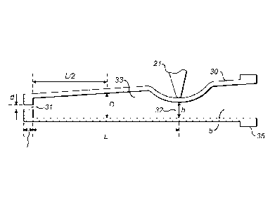
Fig. 3 which discloses a pinched pinch tube in which the
outlet orifice is applied. The pinch tube 30 has an exit
orifice 31 at its downstream end and is pinched closed by
jaw 21 in a region in the vicinity of the opposite end. The
point where it is pinched closed represents the valve outlet
orifice 32 which has a maximum height h measured in the
direction of opening when the valve is fully open. To the
right of this pinch point is the reservoir 5 containing the
inhalable composition. Part of the reservoir is made up by
the right-hand portion of the pinch tube 30, and the
remainder is made up by the device housing as described
above.
Between the valve outlet orifice 32 and the exit
orifice 31 is expansion chamber 33. This has an axial length
L and an internal diameter D which is measured halfway along
the expansion chamber. The exit orifice 31 has a length 1
and a diameter d.
CA 02900487 2015-08-06
WO 2014/155091
PCT/GB2014/050937
- 12 -
Fig. 4 shows how the pinch tube 30 is incorporated into
the inhaler. Where appropriate, the same reference numerals
have been used for the same components to designate
components equivalent to the same components described above
in relation to Figs. 1 and 2. An annular rim 35 at the
opposite to the exit orifice 31 engages with a step 36
within the body of the housing 1 to maintain the pinch tube
30.
The closure of the tube is shown schematically in Fig.
4 in that, rather than penetrating the wall of the pinch
tube 30, the jaw 21 will, in fact, simply compress the tube
as described above.
The axial distance x between the end of the exit
orifice 31 and the outlet end 8 is 1.4 mm. Between the exit
orifice 31 and the outlet end 8 is a flared flow path 37
which is flared with an angle 6 of 51.1 . This short
distance and wide angle of flow path prevents as far as
possible any impingement of the composition leaving the
outlet orifice 31 on the body of the inhaler.
The inhaler has a reservoir volume of approximately 1m1
maintained at a pressure of 600kPa. The opening height (h)
is 0.1mm in the fully opened position. The length (L) is
7.4mm and the diameter (D) is 0.94mm. The exit orifice has a
length (1) of 0.5mm and an internal diameter (d) of 0.2mm.