Note : Les descriptions sont présentées dans la langue officielle dans laquelle elles ont été soumises.
CA 02900767 2016-06-20
54106-1881
CLOUD ENABLED BUILDING AUTOMATION SYSTEM
CROSS REFERENCE TO RELATED APPLICATION
[0001] This application is a continuation-in-part application of U.S.
application number
13/763,870 filed on February 11, 2013 entitled SYSTEM AND METHOD OF ENERGY
MANAGEMENT CONTROL which claims the benefit under 35 U.S.C. 119(e) of U.S.
Provisional Application Number 61/606,630 filed on March 5, 2012.
FIELD OF THE INVENTION
[0002] This invention to energy management control, and more
particularly, to a cloud
enabled energy management control framework to provide optimized control and
operation for
energy efficient buildings.
BACKGROUND OF THE INVENTION
[0003] Many current building automation systems use reactive control
strategies to
monitor and control various systems in a building. For example, the strategies
may include
following schedules and settings created by a facility manager. Referring to
Fig. 1, an
architecture 10 for a reactive building automation system is shown. The
building includes a
facility manager workstation 28 which includes a human machine interface (HMI)
32, data
logger 34 and provides access to a manufacturing execution system (MES) 36. In
addition, the
building includes an engineering workstation 30 which provides access to an
engineering system
(ES) 38. The building automation system includes controllers 12 associated
with actuators 14
and sensors 22 for water heaters/chillers, hot/chilled water pumps,
temperature meters 16, water
and/or air supply valves, flow meters 18, ventilation fans, humidifiers,
thermal mass meters, flow
meters 20, lights, circuit breakers, electricity meters 24 and ventilators,
carbon dioxide (CO2)
meters, luminance meters 26 and other devices and/or sensors. The controllers
12 provide close-
1
CA 02900767 2015-08-07
WO 2014/124353
PCT/US2014/015520
loop and open-loop control of environmental conditions such a temperature,
humidity, air quality
and others. Each controller 12 receives temperature, humidity, luminance and
other settings,
along with schedules of settings, which are input to the MES 36 by a facility
manager via the
HMI 32. Real-time data, such as temperature, humidity, and luminance, is
collected by the
controllers 12 and sent to the HMI 32 and the data logger 34. The facility
manager also monitors
real-time status of the building and reads historical data from the data
logger 34. Further, the ES
38 is used by an engineer to program, monitor, troubleshoot and commission the
building
automation system 10, controllers 12, HMI 32, and data logger 34.
[0004]
However, such strategies do not consider changes in energy prices, such as the
price of electricity, which occur at different times and for different weather
conditions. Thus,
such systems are not cost effective or energy efficient. Another disadvantage
is that occupants in
the building may not be able to control their own environment settings. For
instance, some
occupants prefer 72 F in summer time, and others prefer 75 F .
SUMMARY OF THE INVENTION
[0005] A
method of controlling energy consumption in a building is disclosed. The
method includes receiving occupant request data comprising a plurality of
requests, wherein each
of the plurality of requests corresponds to one of a plurality of zones in the
building wherein the
occupant request data is received via a cloud computing resource. The method
also includes
receiving weather data comprising at least one of current weather measurement
data and weather
forecast data wherein the weather data is received via a cloud computing
resource. In addition, a
facility management rule, created and managed by the facility manager, is
received via a cloud
computing resource. Further, the method includes generating a plurality of
output control signals
via cloud computing resource, wherein each of the plurality of output control
signals is based on
one of a plurality of requests and predicted occupant schedules, energy price
data and the facility
management rule. The control signals are simulated to determine an optimized
control signal
based on optimized energy use or optimized cost.
2
CA 02900767 2016-09-30
54106-1881
[0005a] According to one aspect of the present invention, there is
provided a method of
controlling energy consumption in a building, comprising: receiving occupant
request data
comprising a plurality of requests, wherein each of the plurality of requests
corresponds to one
of a plurality of zones in the building wherein the occupant request data is
received via a
cloud computing resource wherein the occupant request data includes an initial
request
received from an occupant of the building and wherein the initial request is
associated with at
least one initially requested environmental condition; receiving occupant
schedule data
comprising a plurality of predicted occupant schedules, wherein each of the
plurality of
predicted occupant schedules corresponds to one of the plurality of zones in
the building
wherein the occupant request data is received via a cloud computing resource;
receiving
weather data comprising at least one of current weather measurement data and
weather
forecast data wherein the weather data is received via a cloud computing
resource; receiving
energy price data comprising at least one of current energy price data and
predicted energy
price data via a cloud computing resource; receiving sensor and actuator data
comprising data
collected by controllers located in the building wherein the sensor and
actuator data is
received via a cloud computing resource; receiving a facility management rule
via a cloud
computing resource; generating a plurality of output control signals wherein
each of the
plurality of output control signals is based on one of the plurality of
requests, one of the
plurality of predicted occupant schedules, the energy price data and the
facility management
rule and each of the plurality of output control signals is configured to
adjust building control
devices in the plurality of zones in the building wherein the output control
signals are
generated via a cloud computing resource; simulating each of the control
signals via a cloud
computing resource to determine an optimized control signal based on optimized
energy use,
optimized cost and building configuration information input by a building
operator;
determining whether the initial request complies with the facility management
rule; and
transmitting the optimized output control signal to a building automation
system (BAS) of the
building when the initial request complies with the facility management rule
such that the
BAS provides the at least one environmental condition associated with the
initial request,
wherein when the initial request does not comply with the facility management
rule, the BAS
provides a closest value for the environmental condition, relative to the
initially requested
environmental condition, that complies with the facility management rule and
wherein a user
2a
CA 02900767 2016-09-30
54106-1881
making the request is informed that the value for the environmental condition
associated with
the initial request was adjusted to the closest value for the environmental
condition that
complies with the facility management rule.
[0005b] According to another aspect of the present invention, there is
provided a
method of controlling energy consumption in a building, comprising: providing
a run-time
module configured to receive occupant schedule data comprising a predicted
occupant
schedule, and weather data comprising at least one of current weather
measurement data and
weather forecast data wherein the occupant schedule data and weather forecast
data are
provided by a cloud computing resource; providing a human-machine interface
(HMI)
configured to receive occupant request data comprising a current request
wherein the
occupant request data includes an initial request received from an occupant of
the building
and wherein the initial request is associated with at least one initially
requested environmental
condition; simulating each of the control signals via a cloud computing
resource to determine
a simulated signal based on optimized energy use, optimized cost and building
configuration
information input by a building operator; determining whether the initial
request complies
with a facility management rule; and providing an interface module configured
to receive an
output control signal from the run-time module and transmit the output control
signal to a
building automation system (BAS) of a building, wherein the output control
signal is based on
the occupant schedule data, the weather data, the occupant request data, and
the simulated
signal, and wherein when the initial request complies with the facility
management rule the
BAS provides the at least one environmental condition associated with the
initial request, and
wherein when the initial request does not comply with the facility management
rule, the BAS
provides a closest value for the environmental condition, relative to the
initially requested
environmental condition, that complies with the facility management rule and
wherein a user
making the request is informed that the value for the environmental condition
associated with
the initial request was adjusted to the closest value for the environmental
condition that
complies with the facility management rule.
2b
CA 02900767 2015-08-07
WO 2014/124353
PCT/US2014/015520
BRIEF DESCRIPTION OF THE DRAWINGS
[0006] FIG. 1
depicts an architecture for a conventional reactive building automation
system.
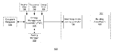
[0007] FIG. 2
shows an energy management control (EMC) system, according to an
exemplary embodiment of the present disclosure.
[0008] FIG. 3
shows the energy management controller of FIG. 1, according to an
exemplary embodiment of the present disclosure.
[0009] FIG. 4
shows the EMC run-time module of FIG. 3, according to an exemplary
embodiment of the present disclosure.
[0010] FIG. 5
is a flowchart showing a method of controlling energy consumption in a
building, according to an exemplary embodiment of the present disclosure.
[0011] FIG. 6
is a flowchart showing a method of controlling energy consumption in a
building, according to an exemplary embodiment of the present disclosure.
[0012] FIG. 7
shows an exemplary computer system for implementing an EMC system,
according to an exemplary embodiment of the present invention.
[0013] FIG. 8
depicts an architecture for the EMC system used in conjunction with a
building automation system.
[0014] FIG. 9
is an alternate architecture for the EMC system when used in a cloud-
enabled building automation system in accordance with the current invention.
3
CA 02900767 2015-08-07
WO 2014/124353
PCT/US2014/015520
DESCRIPTION OF THE INVENTION
[0015] Before
any embodiments of the invention are explained in detail, it is to be
understood that the invention is not limited in its application to the details
of construction and the
arrangement of components set forth in the following description or
illustrated in the following
drawings. The invention is capable of other embodiments and of being practiced
or of being
carried out in various ways. Also, it is to be understood that the phraseology
and terminology
used herein is for the purpose of description and should not be regarded as
limiting. The use of
"including," "comprising," or "having" and variations thereof herein is meant
to encompass the
items listed thereafter and equivalents thereof as well as additional items.
Unless specified or
limited otherwise, the terms "mounted," "connected," "supported," and
"coupled" and variations
thereof are used broadly and encompass direct and indirect mountings,
connections, supports,
and couplings. Further, "connected" and "coupled" are not restricted to
physical or mechanical
connections or couplings. In the description below, like reference numerals
and labels are used
to describe the same, similar or corresponding parts in the several views of
Figs. 1-9.
[0016]
According to exemplary embodiments of the present disclosure, an energy
management control (EMC) system is utilized to permit a building automation
system (BAS) to
utilize different, externally available information to proactively control,
and optimize energy
management. A BAS is a system used by the control system of a building to
monitor and control
various systems in the building. For example, a BAS communicates with building
control
devices in the building to manage the energy consumption in the building. The
types of
information utilized by the EMC system include, for example, weather
information, occupancy
information, and energy market price information. By integrating this
available, useful
information, energy consumption may be decreased, and occupant comfort may be
increased in a
building.
[0017] FIG. 2
shows an energy management control (EMC) system 100, according to an
exemplary embodiment of the present disclosure. In FIG. 2, an energy
management controller
101 receives data, including, for example, weather data 102, occupancy data
103, and energy
price data 104. The weather data may include current weather measurement data
(e.g., the
current temperature) and weather forecast data (e.g., a prediction of the
temperature over an
4
CA 02900767 2015-08-07
WO 2014/124353
PCT/US2014/015520
upcoming time period). The occupancy data may include occupant request data
and occupant
schedule data. The occupant request data is data input by an occupant, and
corresponds to a
current request made by the occupant. For example, an occupant may request
that the
temperature in a zone in the building be set to a specific temperature value.
The occupant
schedule data is data reflecting a predicted occupant schedule for a building.
For example, a
building may include different zones, and each zone may have corresponding
occupant schedule
data. The occupant schedule data may be based on a prediction of the number of
occupants that
will be present in certain zones of the building at certain times, as well as
certain tasks, which
require certain levels of energy consumption, that are scheduled to be
performed in certain zones
of the building at certain times. Energy price data may include current energy
price data (e.g., a
real-time energy price) and/or predicted energy price data for future time
periods provided by an
energy utility or a plurality of energy utilities. A zone in the building may
correspond to a single
room in the building, or to an area in the building including several rooms.
[0018] The data may be input to the energy management controller 101 via a
variety of
means, and is used by the EMC system 100 for optimal planning and operation of
the BAS. For
example, in an exemplary embodiment, the EMC system 100 may include input
means such as,
for example, a touchscreen, a keyboard, a mouse, etc., and a user can manually
input the
different types of data. In an exemplary embodiment, the EMC system 100 may
retrieve the data
from a database, or a plurality of databases. The database(s) may be located
separately from the
EMC system 100, and the EMC system 100 may communicate with the database(s)
via a
network connection (e.g., a wired connection or a wireless connection). The
data may be
received automatically or manually by a user. For example, a user may set a
schedule regarding
the frequency at which the data is retrieved. In addition, the EMC system 100
may receive
occupant requests at block 105 and rules from a facility manager at block 106.
Based on the
received data and input received from an occupant and/or a facility manager,
the EMC system
100 outputs control signals. The output control signals may include, for
example, set-points of
zone temperature, humidity, and luminance, and schedules of building control
devices such as,
for example, a thermostat, HVAC (heating, ventilation and air conditioning),
windows, and
lights.
[0019] During operation, the EMC system 100 may implement a dual-loop
structure. For
example, the EMC system 100 may utilize an inner loop and an outer loop. The
inner loop is
CA 02900767 2015-08-07
WO 2014/124353
PCT/US2014/015520
shown at block 107 of FIG. 2, and enables micro-zoning and performs local
optimization of the
building control devices (block 108) (e.g., HVAC, lighting, windows, etc.)
within the building
used to comply with the set-point requirements output by the EMC system 100.
That is, the inner
loop enables independent control of low level building control devices (block
108) in individual
zones in the building (block 109). A zone in the building may correspond to a
single room in the
building, or to an area in the building including several rooms. Micro-zoning
refers to
individually managing different building control devices in different zones of
the building to
optimize energy consumption in the building. An energy consumption profile may
be
transmitted from the inner loop to the energy management controller 101,
allowing the energy
management controller 101 to make adjustments to the output control signal
transmitted to the
inner loop. The output control signal may include, for example, set-points,
modes, and schedules.
The outer loop functions as a control loop for the main framework of the EMC
system 100,
serving as a high level strategy planner, enabling the BAS to perform a
variety of functions. For
example, the outer loop may enable the BAS to utilize data including, for
example, weather data
102, occupancy data 103, and energy price data 104 to configure an energy
saving strategy and
implement the strategy in real-time. The outer loop may further enable the BAS
to exploit the
building's thermal storage capacity for load shaping, coordinate occupants'
real-time requests for
micro-zoning, plan natural ventilation and cooling, and predict 10 a daily
energy demand profile
for automatic demand response. The outer loop communicates with the inner loop
via an
interface module 205, as described with reference to FIG. 3.
[0020] FIG. 3
shows the energy management controller 101 of FIG. 1, according to an
exemplary embodiment of the present disclosure. As shown in FIG. 3, the energy
management
controller 101 may include a number of components. A human-machine interface
(HMI) 201 is
utilized to communicate with occupants and the facility manager to receive
requests (e.g., from
the occupants) and rules (e.g., from the facility manager). The HMI 201 may
aggregate the
requests and rules to facilitate optimal planning and operation of the BAS.
The HMI 201 may be
implemented in a variety of manners. For example, the HMI 201 may be a
dedicated web-based
HMI, providing occupants with a convenient and easily accessible interface to
control certain
zones and rooms in the building. The web-based HMI may be accessed via any
network
connected device including, for example, a computer, a tablet computer, a
smartphone, etc. The
HMI 201 may include the capability of storing task schedules and preferences
associated with
6
CA 02900767 2015-08-07
WO 2014/124353
PCT/US2014/015520
the tasks. The facility manager may utilize the HMI 201 to receive information
relating to the
occupants' preferences, task schedules, and demand response request (e.g., a
request from a
utility company to reduce energy consumption during periods of high demand),
allowing the
facility manager to implement rules of operations and decisions during a
demand response period
(e.g., decreasing energy consumption).
[0021] A
request arbitrator 202 receives requests input by the occupant and rules input
by
the facility manager, and implements the requests based on the rules. The
requests that comply
with the rules may be implemented by the EMC system 100. For example, if a
user inputs a
request that a temperature in a zone of a building be set to 75 degrees, and
the rules input by the
facility manager specify that the temperature stay within a range of 76
degrees and 78 degrees,
the request arbitrator 202 will not implement the user's request since it is
not in compliance with
the rules. That is, in an exemplary embodiment, if a request is made that is
not in compliance
with the rules, the request is not implemented. Alternatively, if the request
is not in compliance
with the rules, the request arbitrator 202 may implement an alternate change
based on the non-15
compliant request. For example, if a user inputs a request that a temperature
in a zone of a
building be set to 75 degrees, and the rules input by the facility manager
specify that the
temperature stay within a range of 76 degrees and 78 degrees, the request
arbitrator 202 may set
the temperature to the compliant value closest to the user's non-compliant
request (e.g., in the
present example, the request arbitrator 202 may set the temperature to 76
degrees). In this case,
the request arbitrator 202 may generate a notification to be presented to the
user, informing the
user that his or her initial request was non-compliant, and informing the user
that an adjustment
was made based on the closest compliant value to the user's non-compliant
request.
[0022] FIG. 4
shows the EMC run-time module 203 of FIG. 3, according to an
exemplary embodiment of the present disclosure. The EMC run-time module 203
generates
EMC strategies based on input received by the EMC system 100. As described
above, the input
may include, for example, weather data 102, occupancy data 103, and energy
price data 104. In
an exemplary embodiment, the EMC run-time module 203 includes a default
schedule generator
301, a real-time set-points generator 302, and an optimization tool/libraries
module 303.
[0023] The
default schedule generator 301 generates a default schedule including set-
points for pre-determined intervals for every zone in the building. The
default schedule
corresponds to an optimal schedule as determined by the default schedule
generator 301. The
7
CA 02900767 2015-08-07
WO 2014/124353
PCT/US2014/015520
default schedule 10 generator 301 may be configured to generate a new schedule
for any time
interval. For example, the default schedule generator 301 may be configured to
generate a new
schedule every 24 hours, however the time interval is not limited thereto.
Further, the pre-
determined intervals for the set-points for every zone in the building may be
customized. For
example, set-points for each zone may be set to update every hour, however the
intervals are not
limited thereto. In addition, the 15 set-points for different zones and for
different building control
devices may be set to update at different intervals. For example, the
temperature in a first and
second zone may be set to update every 1 hour, the temperature in a third zone
may be set to
update every 3 hours, the lighting system in the first zone may be set to
update every 8 hours,
and the lighting system in the second and third zones may be set to update
every 12 hours.
[0024] The
default schedule generated by the default schedule generator 301 is based on
certain weather data 102 and certain occupancy data 103. For example, the
weather data 102 may
include both weather forecast data 304 and current (e.g., real-time) weather
measurement data
305, and the occupancy data 103 may include both occupant schedule data 306
(e.g., predicted or
preferred occupant schedules and tasks including preferred office hours and
meeting rooms) and
occupant request data 307 (e.g., current requests made by an occupant(s) in
real-time). The
default schedule generator 301 may utilize the weather forecast data 304 and
the occupant
schedule data 306 to generate the default schedule. The default schedule
generator 301 receives
the occupant schedule data 306 from the HMI 201. This schedule may be used by
the BAS as the
default schedule. For example, the default schedule generated by the default
schedule generator
301 may be applied to the BAS when no new real-time set-points are provided by
the real-time
set-points generator 302.
[0025] The
real-time set-points generator 302 generates set-points based on the real-time
occupant request data 307 and the real-time weather measurement data 305. For
example, as the
real-time set-points generator 302 receives requests from an occupant and
receives real-time
weather measurement data, the real-time set-points generator 302 generates set-
points that
override the default schedule generated by the default schedule generator 301.
The EMC run-
time module 203 may seamlessly transition between applying the default
schedule to the BAS
when no set-points have been generated by the real-time set points generator
302, and making 15
adjustments to the default schedule when occupant requests and/or real-time
weather
measurement data is received.
8
CA 02900767 2015-08-07
WO 2014/124353
PCT/US2014/015520
[0026] The
default schedule generator 301 and the real-time set-points generator 302
may both utilize the optimization tool/libraries module 303 and an energy
simulator 204 of the
energy management controller 101 to perform optimization related simulation to
determine
optimal 20 schedules and set-points. For example, the optimization
tool/libraries module 303
may be utilized to perform different types of optimization, including, for
example, heuristic
search based optimization, and may utilize the energy simulator 204 to
implement the
optimization process.
[0027]
Referring to FIG. 3, the energy simulator 204 simulates different EMC
strategies
and determines which strategy is the most energy efficient. The energy
simulator 204 may utilize
existing energy simulation software such as, for example, EnergyPlus. The
energy simulator 204
may communicate with the optimization tool/libraries module 303 of the EMC run-
time module
203 to determine an optimized strategy. The energy simulator 204 may utilize
characteristics of
the building, which may be input by a user (e.g., the facility manager), to
simulate different EMC
strategies. The building characteristics may include, for example, the
building's physical
makeup, including the physical makeup of specific rooms and zones, a
description of the
different types and locations of building control devices in the building,
etc.
[0028] The
interface module 205 is a channel allowing the outer loop to communicate
with the inner loop. Once an EMC strategy is determined and selected by the
EMC system 100 in
the outer loop, this strategy is communicated to the inner loop, and the inner
loop applies the
strategy via local optimization of the building control devices within the
building.
[0029] As
described above, the EMC system 100 allows for the determination,
simulation, and application of different EMC strategies, each of which may
result in different
energy/cost savings. FIG. 5 is a flowchart showing a method of controlling
energy consumption
in a building, according to an exemplary embodiment of the present disclosure.
At block 401,
occupancy data is received by the EMC system 100. The occupancy data may
include occupant
request data and/or occupant schedule data. As described above, the occupant
request data may
include a current request made by an occupant, and the occupant schedule data
may include a
predicted occupant schedule based on occupants in the building and tasks to be
completed in the
building. At block 402, weather data is received by the EMC system 100. As
described above,
the weather data may include current (e.g., real-time) weather measurement
data and weather
forecast data. At block 403, the EMC system 100 generates an output control
signal. The output
9
CA 02900767 2015-08-07
WO 2014/124353
PCT/US2014/015520
control signal is based on the received occupancy data and weather data, and
is configured to
adjust a building control device in a zone in the building. At block 404, the
output control signal
is transmitted to the BAS.
[0030] FIG. 6
is a flowchart showing a method of controlling energy consumption in a
building, according to an exemplary embodiment of the present disclosure. At
block 501,
occupant request data is received by the EMC system 100. The occupant 15
request data may
include a plurality of requests, each of which correspond to one of a
plurality of zones in the
building. At block 502, occupant schedule data is received by the EMC system
100. The
occupant schedule data may include a plurality of predicted occupant
schedules, each of which
corresponds to one of the plurality of zones in the building. At block 503,
weather data is
received by the EMC system 100. The weather data may include current weather
measurement
data and/or weather forecast data. At block 504, a plurality of output control
signals are
generated by the EMC system 100. Each of the plurality of output control
signals is based on one
of the plurality of requests and one of the plurality of predicted occupant
schedules, and each of
the output control signals is configured to adjust building control devices in
the plurality of zones
in the building. At block 505, the output control signals are transmitted to
the BAS. As a result,
micro-zoning may be performed.
[0031]
According to an exemplary embodiment, an occupancy based control strategy
may be implemented by the EMC system 100. The occupancy based control strategy
is based on
the occupancy data 103, and utilizing different set-points based on the
occupancy data 103. For
example, the occupancy data 103 may indicate an occupancy schedule, as well as
occupancy
requests/preferences. The occupancy schedule includes information indicating
at which times
different zones in the building are typically occupied and unoccupied, and may
also indicate the
different tasks performed in the different zones at certain times. A zone may
correspond to a
single room in the building, or to multiple rooms in a certain area of the
building. In addition to
the occupancy schedule, occupancy requests/preferences may be included in the
occupancy data
103. Occupancy requests/preferences include requests input to the EMC system
100 by user(s).
For example, a user may request that a temperature of a certain zone be
increased during certain
times of day, or on different days. If this request complies with rules set by
the facility manager,
as described above, additional set-points may be implemented by the EMC system
100. For
example, using the occupancy based control strategy, basic set-points may be
initially
CA 02900767 2015-08-07
WO 2014/124353
PCT/US2014/015520
implemented based on the occupancy schedule. Additional set-points may then be
implemented
based on occupant preferences and requests.
[0032]
According to an exemplary embodiment, a knowledge based control strategy
(e.g., an occupancy task based control strategy) may be implemented by the EMC
system 100.
The occupancy based control strategy is based on the occupancy data 103
received from a
user(s). For example, the occupancy data 103 may indicate an occupancy
schedule, as well as
occupancy task information. The occupancy schedule includes information
indicating at which
times the building is typically occupied and unoccupied. Further, the
occupancy schedule may
include information indicating at which times certain zones in the building
are typically occupied
and unoccupied. A zone may correspond to a single room in the building, or to
multiple rooms in
a certain area of the building. In addition to the occupancy schedule,
occupancy task information
may be included in the occupancy data 103. Occupancy task information
indicates specific tasks
being carried out in specific zones of the building. For example, tasks may
indicate computer
usage, laboratory usage, heavy reading, etc. Based on this information, set-
points may be
implemented to adjust the lighting in specific zones of the building based on
the tasks being
carried out in those zones.
[0033]
According to an exemplary embodiment, a weather based control strategy may be
implemented by the EMC system 100. The weather based control strategy is a
supplemental
control strategy that can supplement any of the control strategies according
to exemplary
embodiments of the present disclosure. For example, the weather based control
strategy may be
implemented together with any of the time of day control strategy, the
occupancy based control
20 strategy, and the knowledge based control strategy. When the weather based
control strategy
is utilized, the EMC system 100 receives weather data 102 as an additional
input, and uses this
additional data to implement set-points. As a result, the current weather can
be leveraged to
increase energy consumption savings, as described above.
[0034]
According to an exemplary embodiment, a load shifting control strategy may be
implemented by the EMC system 100. The load shifting control strategy limits
energy
consumption during peak load time. Utilization of the load shifting control
strategy may result in
the savings of energy cost. That is, the load shifting control strategy may
reduce the total energy
cost by shifting the load to a time period having a cheaper energy price. For
example, the load 10
shifting control strategy includes pre-cooling or pre-heating zones of a
building prior to the peak
11
CA 02900767 2015-08-07
WO 2014/124353
PCT/US2014/015520
load time. A heuristic search based optimization process may be implemented to
determine the
optimal start time and the duration of the pre-cooling or pre-heating. An
energy cost function
may be defined as the sum of demand cost and energy consumption cost. The
heuristic search
based optimization process may utilize, for example, Particle Swamp
Optimization (PSO) or a
Genetic Algorithm (GA).
[0035] It is
to be understood that exemplary embodiments of the present disclosure may
be implemented in various forms of hardware, software, firmware, special
purpose processors, or
a combination thereof. In one embodiment, a method for energy management
control may be
implemented in software as an application program tangibly embodied on a
computer readable
storage medium or computer program product. As such, the application program
is embodied on
a non-transitory tangible media. The application program may be uploaded to,
and executed by, a
processor comprising any suitable architecture.
[0036] It
should further be understood that any of the methods described herein can
include an additional step of providing a system comprising distinct software
modules embodied
on a computer readable storage medium. The method steps can then be carried
out using the
distinct software modules and/or sub-modules of the system, as described
above, executing on
one or more hardware processors. Further, a computer program product can
include a computer
readable storage medium with code adapted to be implemented to carry out one
or more method
steps described herein, including the provision of the system with the
distinct software modules.
[0037]
Referring to FIG. 7, according to an exemplary embodiment of the present
disclosure, a computer system 1001 for energy management control can comprise,
inter alia, a
central processing unit (CPU) 1002, a memory 1003 and an input/output (I/O)
interface 1004.
The computer system 1001 is generally coupled through the I/O interface 1004
to a display 1005
and various input devices 1006 such as a mouse and keyboard. The support
circuits can include
circuits such as cache, power supplies, clock circuits, and a communications
bus. The memory
1003 can include random access memory (RAM), read only memory (ROM), disk
drive, tape
drive, etc., or a combination thereof The present invention can be implemented
as a routine 1007
that is stored in memory 1003 and executed by the CPU 1002 to process the
signal from the
signal source 1008. As such, the computer system 1001 is a general-purpose
computer system
that becomes a specific purpose computer system when executing the routine
1007 of the present
invention. The computer system 1001 can communicate with one or more networks
such as a
12
CA 02900767 2015-08-07
WO 2014/124353
PCT/US2014/015520
local area network (LAN), a general wide area network (WAN), and/or a public
network (e.g.,
the Internet) via a network adapter. In addition the computer system 1001 may
be used as a
server as part of a cloud computing system where tasks are performed by remote
processing
devices that are linked through a communications network. In a distributed
cloud computing
environment, program modules may be located in both local and remote computer
system
storage media including memory storage devices.
[0038] The
computer platform 1001 also includes an operating system and micro-
instruction code. The various processes and functions described herein may
either be part of the
micro-instruction code or part of the application program (or a combination
thereof) which is
executed via the operating system. In addition, various other peripheral
devices may be
connected to the computer platform such as an additional data storage device
and a printing
device. Examples of well-known computing systems, environments, and/or
configurations that
may be suitable for use with computer system 1001 include, but are not limited
to, personal
computer systems, server computer systems, thin clients, thick clients, hand-
held or laptop
devices, multiprocessor systems, microprocessor-based systems, set top boxes,
programmable
consumer electronics, network PCs, minicomputer systems, mainframe computer
systems, and
distributed cloud computing environments that include any of the above systems
or devices, and
the like.
[0039]
Referring to Fig. 8, an architecture 110 for the EMC system 100 used in
conjunction with a BAS is shown. The architecture 110 includes occupant
workstations 112
having the HMI 201, a web server 114 along with the engineering workstation 30
and facility
manager workstation 28. The occupant workstations 112, engineering workstation
30, facility
manager workstation 28, first web server 114 and controllers 12 are connected
by a network 116.
In use, the facility manager creates facility manager data 106 which includes,
for example, rules
for temperature, humidity, luminance and other settings via HMI 201. Occupants
create
occupancy data 103 such as schedules (for example, when the occupant will be
in and out of
office) and preferences for temperature, humidity, luminance and other
settings. The schedules
and preferences are then saved to the first web server 114. According to an
exemplary
embodiment, a time of day control strategy may be implemented by the EMC
system 100. The
time of day control strategy is based on a business hours schedule in which
fixed set-points are
utilized during business hours. For example, if typical business hours for a
building are defined
13
CA 02900767 2015-08-07
WO 2014/124353
PCT/US2014/015520
as 9:00am to 5:00pm, fixed set-points increasing energy use may be implemented
at the start of
the business day (e.g., 9:00am), and fixed set-points decreasing energy use
may be implemented
at the end of the business day (e.g., 5:00pm). The time of day control
strategy is not limited to
business hours. For example, the time of day strategy may be utilized in a
home setting using
different, fixed set-points utilized during different hours (e.g., hours
corresponding to the typical
time occupants' are at home).
[0040] The EMC
system 100 receives the occupancy data 103, facility manager data 106
and energy price data 104 along with associated historical data, and a
physical makeup or model
of an associated building from the first web server 114. By way of example,
the energy price
data 104 may include electricity prices and historical data for the
electricity prices. The EMC
system 100 also receives weather data 102 which includes the weather forecast
data 304 and
current (e.g., real-time) weather measurement data 305, from the Internet 120.
The EMC system
100 then generates multiple schedules for optimization. Energy simulation
software such as
EnergyPlus and TRNSYS, or energy simulation software developed via MATLAB, is
then used
by the energy simulator 204 to compute energy consumption and cost for each
generated
schedule. The EMC system 100 then sends the most suitable schedule in terms of
optimized
energy consumption and cost to the controllers 12. Thus, the EMC system 100
provides a
proactive and predictive control strategy.
[0041] The EMC
system 100 performs an optimization calculation once per day with
given weather data 102, facility manager data 106, occupant data 103, energy
price data 104 and
building modeling data. The EMC system 100 calculates energy consumption and
cost for
multiple schedules (for example 10 schedules), whose granularity could be
hour, 30 minutes and
even 15 minutes, perhaps by using different energy simulation software tools.
The EMC system
100 provides a proactive control strategy wherein an optimized schedule is
generated that is
based on prior knowledge of building physical model, weather forecast
information, occupant
schedule data and multiple schedules of settings.
[0042] In an
embodiment, the current invention is configured to operate in a cloud
computing environment. Cloud computing provides access to computing resources
such as
networks, network bandwidth, servers, processing, memory, storage,
applications, virtual
machines, services, software and others that reside on the Internet 120.
Referring to Fig. 9, an
alternate architecture 130 for the EMC system 100 when used in a cloud-enabled
building
14
CA 02900767 2015-08-07
WO 2014/124353
PCT/US2014/015520
automation system in accordance with the invention is shown. The architecture
130 includes a
data server 132 that stores historical data, building modeling data, location
information, rule
setting by the facility manager, energy price plan, occupant preferences and
schedules, default
schedules and settings. In addition, the data server 132 stores sensor and
actuator data collected
by the controllers 12 which also form part of the inner loop. By way of
example, the sensor data
may include information such as a temperature reading and the actuator data
may include
information regarding activation of a fan or the speed of the fan. In
addition, the architecture
130 includes a cloud-enabled proxy server 134 which runs default schedules and
settings if cloud
computing resources are not available. Further, the architecture 130 includes
a cloud based
building automation service (CBAS) 136 that is available over the Internet 120
as part of a cloud
computing environment. Cloud computing resources, for example a computer
system/server, are
used to run the CBAS 136. The CBAS 136 communicates with a cloud-enabled
gateway server
138 that collects all local data, such as data from date server 132, and
negotiates with the CBAS
136 and receives optimized schedules and settings from CBAS 136. Another
function of the
gateway server 138 is to separate building control system, controllers 12 and
the data server 132,
from the Internet 120, which connects cloud service, occupants, service
providers' applications,
etc.
[0043]
Occupants can create and modify their schedules and preferences via a web
server
140 provided by the CBAS 136. In addition, the facility manager can monitor
meters, sensors 22
and actuators 14 of the building create and modify schedules and rules via
another web server
142 provided by the CBAS 136. Further, engineers can program, troubleshoot and
commission
the automation systems via an engineering system (ES) server 144 provided by
the CBAS 136.
Note that servers 140, 142 and 144 are independent servers logically. The
servers 140, 142 and
144 can run on one computer physically, or run on different virtual machines
provide by the
cloud service provider. An ES service 146 for monitoring the building, a
simulation service 148
for providing access to energy simulation software such as EnergyPlus and
TRNSYS or energy
simulation software developed via MATLAB to compute energy consumption, and
other
services 150, such as continuous commissioning services for optimizing energy
use for existing
buildings and demand response services for managing energy usage in response
to supply
conditions, may each be provided by a network host. Alternatively, the ES
service 146,
simulation service 148 and other services 150 may be provided via an internet
based subscription
CA 02900767 2015-08-07
WO 2014/124353
PCT/US2014/015520
service that charges a fee for each use. Similarly, the CBAS 136 may provide
access to an
internet based weather service 152. The CBAS 136 generates optimized schedules
and settings
in terms of energy usage and cost based on occupant data, facility manager
setting rules, building
modeling data, energy price and weather forecast data.
[0044] The
CBAS 136 provides an interface for occupants to create their own
preferences and schedules. In addition, the CBAS 136 provides an interface for
the facility
manager to monitor building information, such as temperature and humidity, and
create rules and
schedules and settings and to obtain historical data. Further, the CBAS 136
provides an interface
for an engineer to access the ES service 146 to program, monitor, troubleshoot
and commission
controllers 12. The CBAS 136 may be accessed over the Internet 120 via a web
browser by an
engineer, facility manager or an occupant via the engineering 30, facility
manager 28 and
occupant 112 workstations, respectively, wherein the workstations may be
either a desktop or
mainframe computing device, a mobile computing device such as a laptop
computer or a hand
held computer and combinations thereof. The CBAS 136 provides proactive
control to improve
energy efficiency and reduce energy cost.
[0045] In
accordance with the invention, ownership of ES service and simulation
software is not required. Instead, users are charged per use, thus reducing
costs. Further, use of
cloud resources provides additional computational power that facilitates
simulation of energy
use. In addition, the architecture 130 provides additional scalability since
additional simulation
tools such as EnergyPlus, TRNSYS and MATLAB may be used. Further, additional
scalability
enables the generation and comparison of additional schedules and settings. In
addition, the ES
service 146 and simulation tools provided via the simulation service 148 can
be used for multiple
buildings, thus increasing the utilization of such services and tools.
[0046] It is
to be further understood that, because some of the constituent system
components and method steps depicted in the accompanying figures may be
implemented in
software, the actual connections between the system components (or the process
steps) may
differ depending upon the manner in which the present disclosure is
programmed. Given the
teachings of the present disclosure provided herein, one of ordinary skill in
the related art will be
able to contemplate these and similar implementations or configurations of the
present invention.
[0047] Having
described exemplary herein, it is noted that modifications and variations
can be made by persons skilled in the art in light of the above teachings. It
is therefore to be
16
CA 02900767 2015-08-07
WO 2014/124353
PCT/US2014/015520
understood that changes may be made in exemplary embodiments of the
disclosure, which are
within the scope and spirit of the invention as defined by the appended
claims. Having thus
described the present disclosure with the details and particularity required
by the patent laws,
what is claimed and desired protected by Letters Patent is set forth in the
appended claims.
17