Note : Les descriptions sont présentées dans la langue officielle dans laquelle elles ont été soumises.
TRENCHLESS REFURBISHMENT
OF UNDERGROUND PIPES
RELATED APPLICATIONS
[0001]
FIELD OF THE DISCLOSURE
[0002] This disclosure is directed generally to methods for refurbishing
buried expandable
pipes without open cut replacement (i.e., without digging the pipe out of the
ground). This
disclosure is further directed to items of equipment that facilitate the
disclosed refurbishment
methods.
BACKGROUND
[0003]
The tenn "expandable", as applied to an existing buried pipe or culvert, is
used as a
defined temi of art throughout this disclosure. By "expandable", this
disclosure refers to culverts
and pipes having an existing wavy or folded annular or circumferential
profile, such that,
responsive to a controlled radial force, the "waves" or "folds" will collapse
or "smooth out",
allowing a limited expansion of the effective inside diameter of the pipe
without intentionally
rupturing the pipe. It is expected that many culverts or pipes falling within
this definition will be
metal, and will be corrugated or "accordion" in profile. However, the temi is
not limited to
corrugated or accordion profiles on metal pipes or culverts.
- 1 -
Date Recue/Date Received 2021-01-22
CA 02902602 2015-08-28
[0004] Expandable culverts of interest in this disclosure primarily include
buried pipes that
carry, for example, water under roads and structures, usually to allow a
stream to flow under a
road or to carry runoff from the uphill side of a road to the downhill side.
Utility piping and
other infrastructure may also be carried within such culverts. Such culverts
can be made from
various materials, but are often made from corrugated metal because it
provides flexibility and
strength while remaining relatively light and inexpensive. Consequently,
expandable metal pipe
culverts have been widely used in road construction projects over the last 50
years.
[0005] The service life of an expandable metal culvert varies, depending on
factors such as
climate, maintenance, water flow, and the condition of the surrounding soil.
However, this type
of culvert came into widespread use in the 1950s, and many are now reaching
the end of their
useful life and need to be repaired or replaced (or refurbished) before they
fail. Expandable
metal culverts can fail in different ways. For example, rust and corrosion can
cause the pipe to
leak, or even to disintegrate and collapse. Leaks can lead to erosion around
the pipe and the
resulting lack of structural support can cause the pipe to break. Pipe failure
can wash out roads
and bridges and cause environmental damage to the waterways they drain into.
[0006] Culverts can be repaired, or refurbished, by building a new culvert or
digging the
existing pipe up and replacing it ("open cut" methods). But these methods can
be costly and
time-consuming. Further, open cut methods may impractical because of traffic
volume (the road
will likely have to be closed during open cut operations), terrain, or
climate. However, culverts
can sometimes be refurbished without digging them up. This process is referred
to in the
industry as trenchless replacement technology. In this method, a new pipe is
attached to a tool
that is pushed or pulled through the existing damaged pipe. The tool head
intentionally breaks or
splits the old pipe as it drags the new liner pipe in behind it (this
technique is also called "pipe
- 2 -
CA 02902602 2015-08-28
bursting"). These methods allow culverts to be replaced with minimal
disruption to traffic flow
on any roadway above the culvert and with less impact on the waterway the
culvert drains into.
However, it should be noted that such "pipe bursting" techniques are
"destructive" to the host
pipe (i.e., the old pipe being replaced), rendering the host pipe effectively
useless to provide
support or peripheral protection, for example, to a new liner pipe.
[0007] One example of the destructive "pipe bursting" technology in use today
is disclosed in
Unitracc publication "Hydraulic and Static Pipe Bursting", February 16, 2011,
available as of the
date of this disclosure at:
http://www.unitracc.com/know-how/fachbuecher/rehabilitation-and-maintenance-of-
drains-and-
sewers/rehabilitationireplacement-erilreplacement-bv-the-trenchless-method-
en/unmanned-
techniques-en/pipe-bursting-en/hydraulic-and-static-pipe-bursting-en.
According to this
reference, a hydraulically expandable tool head shatters a surrounding
existing brittle host pipe
(typically clay or unreinforced concrete) as it is drawn down the length of
the existing pipe. A
replacement pipe follows close behind the tool head.
[0008] A further example of current trenchless technology is disclosed in U.S.
Patent No.
4,602,495 to Yarnell. Yarnell is a "non-destructive" alternative to
destructive "pipe bursting"
techniques such as disclosed in Unitracc, described above. Yarnell teaches an
expandable tool
head being drawn down an existing brittle host pipe in which -irregularities"
have made it
difficult, for example, to draw a new liner pipe through the pipe. Such
"irregularities" include
neighboring sections of existing pipe becoming misaligned and no longer
coaxial, or soil
pressure causing sections of the brittle pipe to fracture and partially
collapse, constricting the
original inner diameter of the pipe. A conical nose and expandable "leaf
members- on the tool
head temporarily remediate the "irregularities-, primarily by pushing the
broken host pipe back
- 3 -
CA 02902602 2015-08-28
against soil pressure, so that the effective original internal diameter of the
host pipe can be
temporarily restored. At that point, an inner liner pipe can be drawn through.
[0009] Current destructive trenchless methods for replacing or refurbishing
culverts are
inadequate for some kinds of host pipes. Existing cutting and bursting
techniques have had
limited success on host pipes made from expandable materials such as
corrugated metal. The
principle upon which current technology "bursts" pipe requires a conical front
end of the tool
head (or "cutting head") to be dragged through the existing pipe, forcing the
pipe over the body
of the cutting head until it fractures or "bursts". The outside diameter of
the body of the cutting
head is thus chosen to be larger than the inside diameter of the pipe, causing
the pipe to rupture
as the cutting head is dragged through. There is thus a force placed on the
existing pipe by the
cutting head that has both longitudinal and radial components. Problems arise
when this
technique is used on flexible and expandable pipes such as corrugated pipes.
Rather than
bursting or splitting corrugated pipes, conventional techniques often compress
the pipe
longitudinally, which can cause the pipe to fold up in front of the tool like
an accordion. Not
only does this accordion effect make the overall pipe replacement process
slower and more
expensive, it can potentially cause the tool to get stuck in the old pipe or
block the path for the
new pipe. An existing expandable pipe may become so badly "accordioned" that a
section may
require spot digging and removal in order to complete the overall replacement
job.
100101 Further, non-destructive pipe replacement techniques in the prior art
(such as the
Yarnell disclosure, described above) have been directed to temporarily
restoring an ailing host
pipe to as close its original condition as possible, so that an inner liner
pipe can be installed.
Because the host pipe is temporarily restored to its original condition (or
close to original), the
thickness of the liner pipe, once installed, inevitably reduces the
operational diameter of the
- 4 -
CA 02902602 2015-08-28
repaired pipe. In applications where pipe flow or capacity is important, such
operational
diameter reduction can become disadvantageous.
SUMMARY OF DISCLOSED TECHOLOGY AND TECHNICAL ADVANTAGES
[0011] The tools and processes described in this disclosure address the
problems set forth in
the "Background" section above, and other problems in the prior art. The
described methods
reject the prior art notion of relying on a pulling force to split the host
pipe in destructive mode.
In a first embodiment, a first refurbishment method utilizes a cylindrical
hydraulic tool that
expands and contracts in non-destructive mode. The tool is inserted into the
host pipe via
tensioned cables and hydraulically powered segments or stabilizers on the
outside surface of the
tool expand outward in a radial direction. In some variations of the first
embodiment, the
expansion tool may be functionally not dissimilar from the tool disclosed in
Yarnell. In other
variations, the expansion tool may be in accordance with a new design as
disclosed herein with
reference to FIGURES 17A through 17D and associated text.
[0012] The first refurbishment method is deployed on expandable host pipes
such as
corrugated host pipes. The expansion of the tool imparts radial force only
against the inside
surface of the host pipe, perpendicular to its longitudinal axis. The goal of
the expansion step is
to "smooth out" the "waves" in the periphery of the host pipe via radial
force, without
intentionally rupturing the host pipe. It is understood that in places, the
wall of the host pipe may
break unintentionally, especially where the host pipe is corroded or cracked.
However, because
the applied radial force is perpendicular to the pipe wall, it does not fold
or bunch the host pipe.
Further, with careful application of the first refurbishment method, such
ruptured zones of host
pipe should be limited. The structural integrity of the expandable host pipe
is thus substantially
- 5 -
CA 02902602 2015-08-28
preserved wherever possible, allowing the host pipe to provide support or an
external layer of
protection, for example, to the inner liner pipe when it is installed.
[0013] In a second embodiment, a second refurbishment method includes a
designated cutting
step to cut the host pipe longitudinally, in situ, along its entire length,
prior to expansion. In this
second embodiment, the expansion of the host pipe enlarges the host pipe's
diameter by
separation of the host pipe material either side of the cut line, rather than
"smoothing out" the
"waves" in the periphery of the host pipe (per the first refurbishment
method). Advantageously
the host pipe cut line is at the low point ("invert" or nadir) of the pipe,
although this disclosure is
not limited in this regard. Examples of situations when the second
refurbishment method
(longitudinal cut line) might be selected over the first refurbishment method
(smoothing out
waves) include: (1) when the host pipe is particularly corroded and brittle,
and less susceptible to
consistent plastic radial deformation of the periphery waves; (2) when the
wall of the host pipe is
particularly thick, or has been constructed with a number of overlapping metal
joints, again
making it difficult to obtain consistent plastic radial deformation of the
periphery waves. It will
be nonetheless appreciated that in accordance with the second refurbishment
method
(longitudinal cut line), as with the first refurbishment method (smoothing out
waves), the
structural integrity of the host pipe is thus substantially preserved wherever
possible, allowing
the host pipe to provide support for, or an external layer of protection to,
the inner liner pipe
when it is installed. In this way, expansion of the host pipe via non-
destructive plastic
deformation optimizes the refurbishment job and enables the original host
pipe, as expanded, to
contribute structurally to the refurbished pipe system.
[0014] Regardless of whether the first refurbishment method (smoothing out
waves) or the
second refurbishment method (longitudinal cut line) is selected, the host pipe
is expanded section
- 6 -
CA 02902602 2015-08-28
by section, each section being approximately the same length of the tool.
Presently preferred
embodiments of the tool may be 4 -- 6 feet in length, although this disclosure
is not limited in this
regard. Once a section of host pipe is expanded, the expandable members on the
tool are fully
retracted. The tool is then advanced further into the host pipe and the next
section is expanded.
Once the host pipe is completely expanded, the new liner pipe can be installed
via conventional
methods, such as sliplining. The new liner pipe has a rigid tubular profile
prior to installation
and is deployed to operationally replace the host pipe.
[0015] Once the new liner pipe is installed, it is then stabilized in
preparation for grouting the
annular space between the host pipe and the liner pipe. The inner liner pipe
may be stabilized,
for example, by filling it with a fluid (such as water), or alternatively
pressurizing it internally.
Once the inner liner pipe is stabilized, grout or a similar material is
injected under pressure into
the annular space between the host pipe and the new liner pipe. The purpose of
stabilizing the
inner liner pipe is to give the inner liner pipe strength against deformation
or collapse while the
grout is being injected around it in liquid form. Once the grout has cured,
inner liner pipe
stabilization measures can be removed (e.g. via emptying the fluid or de-
pressurizing the pipe).
It should be noted that in the embodiments illustrated and described below,
the annular space is
filled with grout as much as possible, and advantageously completely filled.
However, in other
embodiments (not illustrated or described below) the annular space is at least
partially filled with
grout.
[0016] Some variations of the grouting phase (according to either the first or
second
refurbishment methods) deploy inflatable bulkheads at each end of the annular
space between the
host pipe and the liner pipe. An example of such an inflatable bulkhead is
disclosed below with
reference to FIGURES 20 - 21 and associated text. Once inflated, the bulkheads
temporarily seal
- 7 -
CA 02902602 2015-08-28
the annular space at either end, (1) allowing the annular space to be filled
efficiently and cleanly
with grout, and (2) holding the grout in place at the ends while it cures.
Structure in at least one
bulkhead includes a grout hose fitting that passes through the inflated
chamber of the bulkhead,
allowing grout to be injected into the annular space while the bulkhead is
inflated.
[0017] In some situations in the first refurbishment method (smoothing out
waves), an
additional step of cutting a section of the host pipe may be required prior to
expanding and
plastically deforming the waves in the periphery of the pipe. As already
noted, in some
situations the host pipe may have become corroded, especially near the bottom
(or "invert") if
the pipe has been exposed to standing water for long periods. Such corroded
portions of the host
pipe are inelastic and likely to crack or shatter when expanded. A controlled
cut of the host pipe
prior to expansion facilitates proper execution of the expansion step in such
corroded portions.
[0018] In other situations, characteristics of the host pipe itself may
require that an additional
step of cutting the host pipe may be advantageous prior to expanding the host
pipe. For example,
a common process for manufacturing corrugated host pipes involves helically
rolling a
continuous length of metal and forming it into a pipe with a spiral scam. Such
spiral seams may
be welded, riveted, or otherwise formed into an inelastic helical pathway
along the finished host
pipe. Applying expansion forces to these inelastic seams may cause the pipe to
crack or burst at
the seam. Alternatively the seams may be so strong that they resist and defeat
the expansion step
in the host pipe areas surrounding the seam. In such cases, similar to the
situations described
above with respect to corroded host pipe, a controlled cut of the host pipe
prior to expansion
facilitates proper execution of the expansion step.
100191 Adding a cutting step prior to expansion of the host pipe may also be
advantageous at
the joints between lengths of host pipe as found in situ. When originally
laid, lengths of host
- 8 -
CA 02902602 2015-08-28
pipe may be joined by any conventional method, such as riveting, welding, or
bolting together.
Lengths of host pipe may have been -folded over" at the ends during
installation, to facilitate
engagement between neighboring lengths during the joining process.
Alternatively, special
"joint pieces" may have been used, in which a short piece of oversized host
pipe is deployed over
both ends of the host pipe pieces to be joined. The joint piece is then
tightened down around
both ends of the host pipe via band-type threaded fasteners. As a result,
joints between lengths
of host pipe in situ may present double or more the wall thickness, as well as
further inelasticity
due to the specific type of joining process originally used. As before,
applying expansion forces
to these inelastic joints may cause the host pipe to crack or burst at the
joint. Alternatively the
joints may be so strong that they resist and defeat the expansion step in the
host pipe areas
surrounding the joint. In such cases, similar to the situations described
above with respect to
corroded host pipe or a helical seam, a controlled cut of the host pipe prior
to expansion
facilitates proper execution of the expansion step.
10020] According to a first embodiment, therefore, this disclosure describes a
method for
refurbishing an existing expandable pipe, the method comprising the steps of,
in sequence: (a)
providing an existing expandable host pipe, the host pipe having an expandable
interior wall with
a known unobstructed internal diameter; (b) providing an expansion tool having
expansion and
retraction modes, the expansion tool adapted to generate isolated outward
radial force when in
expansion mode, (c) moving the expansion tool along a path inside the host
pipe, the path having
stations at which the expansion tool stops; (d) expanding the host pipe during
step (c), step (d)
further including, at each station: (dl) stopping the expansion tool; (d2)
placing the expansion
tool in expansion mode; (d3) engaging the interior wall of the host pipe with
the expansion tool
while in expansion mode; (d4) responsive to isolated outward radial force from
the expansion
- 9 -
CA 02902602 2015-08-28
tool, increasing the unobstructed interior diameter of the host pipe a
predetermined amount via
non-destructive plastic deformation of the interior wall; (d5) switching the
expansion tool to
retraction mode; and (d6) moving the expansion tool to the next station; (e)
withdrawing the
expansion tool from the host pipe; (f) inserting a rigid liner pipe inside the
host pipe, the liner
pipe having a rigid tubular profile prior to insertion and deployed to
operationally replace the
host pipe, an annular space created between the liner pipe and host pipe when
the liner pipe is
inserted inside the host pipe; and (g) at least partially filling the annular
space with grout.
[00211 According to a second embodiment, this disclosure describes a method
for refurbishing
an existing pipe, the method comprising the steps of, in sequence: (a)
providing an existing host
pipe, the host pipe having a length, the host pipe further having an interior
wall with a known
unobstructed internal diameter; (b) making a longitudinal cut through the
interior wall along the
length of the host pipe; (c) providing an expansion tool having expansion and
retraction modes,
the expansion tool adapted to generate isolated outward radial force when in
expansion mode; (d)
moving the expansion tool along a path inside the host pipe, the path having
stations at which the
expansion tool stops; (e) expanding the host pipe during step (d), step (e)
further including, at
each station: (el) stopping the expansion tool; (e2) placing the expansion
tool in expansion
mode; (e3) engaging the interior wall of the host pipe with the expansion tool
while in expansion
mode; (e4) responsive to isolated outward radial force from the expansion
tool, increasing the
unobstructed interior diameter of the host pipe a predetermined amount via non-
destructive
plastic separation of the longitudinal cut through the interior wall; (e5)
switching the expansion
tool to retraction mode; and (e6)
moving the expansion tool to the next station; (f)
withdrawing the expansion tool from the host pipe; (g) inserting a rigid liner
pipe inside the host
pipe, the liner pipe having a rigid tubular profile prior to insertion and
deployed to operationally
- 10-
CA 02902602 2015-08-28
replace the host pipe, an annular space created between the liner pipe and
host pipe when the
liner pipe is inserted inside the host pipe; and (h) at least partially
filling the annular space with
grout.
[0022] According to a third embodiment, this disclosure describes a method for
refurbishing an
existing pipe, the method comprising the steps of, in sequence: (a) providing
an existing host
pipe, the host pipe having a length, the host pipe further having an interior
wall with a known
unobstructed internal diameter; (b) making a longitudinal cut through the
interior wall along the
length of the host pipe; (c) providing a generally elongate cylindrical
expansion tool, the
expansion tool having an end assembly rotatably connected to an expansion
assembly, the end
assembly including at least two extendable radial stabilizers, the expansion
assembly including a
stationary radial force surface generally opposed to a floating radial force
surface, the expansion
assembly adapted to generate isolated outward radial force when actuated by
displacing the
floating radial force surface away from the stationary radial force surface;
(d) moving the
expansion tool along a path inside the host pipe, the path having stations at
which the expansion
tool stops; (e) expanding the host pipe during step (d), step (e) further
including, at each station:
(el) stopping the expansion tool; (e2) extending the radial stabilizers to
engage the interior wall
of the host pipe and hold the end assembly rotationally immobile; (e3)
actuating the expansion
assembly until the stationary radial force surface and the floating radial
force surface exert
isolated outward radial force on opposing portions of the interior wall of the
host pipe; (e4)
responsive to step (e3), and locally at the stationary radial force surface
and the floating radial
force surface, increasing the unobstructed interior diameter of the host pipe
a first predetermined
amount via non-destructive plastic separation of the longitudinal cut through
the interior wall;
(e5) de-actuating the expansion assembly until at least one of the stationary
radial force surface
- 11 -
CA 02902602 2015-08-28
and the floating radial force surface disengages from the interior wall; (e6)
rotating the expansion
assembly a predetermined rotational displacement with respect to the end
assembly; (e7)
repeating steps (e3) through (e6) until the unobstructed interior diameter of
the host pipe is
increased overall at least a second predetermined amount via non-destructive
plastic separation
of the longitudinal cut through the interior wall; (e8) retracting the radial
stabilizers until at least
one of the radial stabilizers disengages from the interior wall of the host
pipe; and (e9) moving
the expansion tool to the next station; (f) withdrawing the expansion tool
from the host pipe; (g)
inserting a rigid liner pipe inside the host pipe, the liner pipe having a
rigid tubular profile prior
to insertion and deployed to operationally replace the host pipe, an annular
space created
between the liner pipe and host pipe when the liner pipe is inserted inside
the host pipe; and (h)
at least partially filling the annular space with grout.
[0023] The processes and tools described in this disclosure provide several
advantages
compared with conventional methods. First, as noted already, because the
expansion forces are
controlled and perpendicular to the host pipe wall, issues with the pipe
folding up like an
accordion are obviated. The disclosed processes are further non-destructive
and preserves
wherever possible the integrity of the host pipe, so that the host pipe may
continue to contribute
to operational longevity once the pipe refurbishment job is finished.
[0024] "I he disclosed processes further expand the outside diameter of the
host pipe (by
removing the existing "waves" or "folds", or by separating the host pipe
either side of a
controlled cut), leaving the host pipe larger in diameter than before.
Introducing the inner liner
pipe may thus, in certain applications, preserve the operational diameter of
the pipe once the
refurbishment job is finished. This
retention of operational diameter may be highly
advantageous in applications where pipe flow or capacity is important.
- 12 -
CA 02902602 2015-08-28
[0025] Another advantage of the disclosed processes is that the host pipe is
completely
expanded before the inner liner pipe is introduced (by sliplining or other
conventional methods).
In the prior art, and particularly in pipe bursting techniques that are
destructive to the host pipe,
the inner liner pipe is generally inserted to follow right behind the bursting
tool as the tool moves
along the host pipe. Causing the inner liner pipe to follow right behind the
bursting tool avoids
premature collapse of the surrounding soil into the tunnel void created by the
burst host pipe.
However, coordination of deployment of the inner liner pipe right behind the
pipe bursting can
make the logistics of the job difficult. Further, should there be an
unintended collapse of the
surrounding soil before the inner liner pipe can provide support, the inner
liner pipe can become
stuck, putting success of the job in jeopardy.
[0026] By contrast, the new processes described in this disclosure fully
expand the host pipe,
and substantially retain the host pipe's structural integrity, before the
inner liner pipe is
introduced. Since the host pipe is completely ready to receive the inner liner
pipe, and is still
supporting the surrounding soil, the inner liner pipe can be deployed quickly
and efficiently
using conventional methods such as sliplining. The disclosed processes are
thus predictive of a
much higher job success rate. Moreover, unlike refurbishment methods of the
prior art (such as
pipe bursting), the new processes of this disclosure create an annular space
in which grout can be
deployed, further enhancing the strength, performance and longevity of the
finished
refurbishment job.
100271 Another advantage of the disclosed processes (and particularly those
embodiments
including cutting steps), is that they may achieve better results when applied
to host pipes
manufactured with a spiral seam. As noted, this type of pipe is constructed
from a coil of metal
that is formed into a pipe with a helical seam. The edges of the seam may be
folded together
- 13-
CA 02902602 2015-08-28
along the entire length of the pipe to create a rigid body that is typically
stronger than pipes with
a longitudinal seam, making conventional pipe bursting difficult. Because the
expansion forces
in the processes described in this disclosure are applied perpendicular to the
host pipe wall, the
spiral seam may unravel and elongate without the "accordion" effect mentioned
above.
Alternatively, in embodiments including cutting steps, longitudinal cuts on
the spiral seam allow
proper execution of the expansion step. Thus, the integrity of the host pipe
and its contribution
to supporting the new pipe are preserved, even in operations where the host
pipe is manufactured
with a spiral seam.
[0028] It will be understood that host pipe expansion via unraveling of a
spiral seam (per the
previous paragraph), or following controlled cutting of the host pipe (per
earlier disclosure), may
be in addition to "smoothing out" the waves or folds in a corrugated or other
expandable host
pipe. The radial force provided by the expansion tool will enable both
operations, thus
expanding the host pipe by (1) increasing the circumference of the host pipe
by unraveling the
spiral seam, and/or (2) increasing the circumference of the host pipe by
separating the host pipe
material either side of the cut in the host pipe, and/or (3) "smoothing out"
the waves or folds in
the host pipe.
[0029] The grout (or other material) injected into the annular space between
the host pipe and
new liner pipe provides additional advantages over conventional trenchless
methods, which
typically omit this step. First, it secures the new liner pipe in position so
it does not move or
settle. Next, the grout fills voids in the soil under the host pipe, reducing
the likelihood of pipe
deflections from differential settlement. The grout also fills voids in the
soil above the host pipe,
which reduces point loads and impacts caused if those voids collapse (which is
a major source of
operational deflection and collapse of culverts).
- 14-
[0030] The foregoing has outlined rather broadly some of the features and
technical
advantages of the disclosed trenchless pipe refurbishment technology, in order
that the detailed
description that follows may be better understood. Additional features and
advantages of the
disclosed technology may be described. It should be appreciated by those
skilled in the art that
the conception and the specific embodiments disclosed may be readily utilized
as a basis for
modifying or designing other structures for carrying out the same inventive
purposes of the
disclosed technology, and that these equivalent constructions do not depart
from the spirit and
scope of the technology as described.
BRIEF DESCRIPTION OF THE DRAWINGS
[0031] For a more complete understanding of the embodiments described in
this disclosure,
and their advantages, reference is made to the following detailed description
taken in conjunction
with the accompanying drawings, in which:
[0032] FIGURES 1 through 12 are a "freeze frame" series of illustrations of
operations in
accordance with a first embodiment of the disclosed technology (the "first
refurbishment
method" as described in the "Summary" section above);
[0033] FIGURE 1A is a section as shown on FIGURE 1;
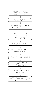
[0034] FIGURE 13 is a flow chart illustrating a first embodiment of a
method of refurbishing
an underground pipe in accordance with the disclosed technology (the "first
refurbishment
method" as described in the "Summary" section above);
[0035] FIGURE 14 is a flow chart illustrating a variation of the method of
FIGURE 13, adding
a cutting step;
- 15 -
Date Recue/Date Received 2021-01-22
CA 02902602 2015-08-28
[0036] FIGURES 15, 16, 18A through 18G, 19 and 22 illustrate a "freeze frame"
series of
operations in accordance with a second embodiment of the disclosed technology
(the "second
refurbishment method" as described in the "Summary" section above);
[0037] FIGURES 17A through 17D illustrate features and aspects of one
embodiment of
expansion tool 700 that may be used generally for tubular expansion, including
in association
with either the "first refurbishment method" or the "second refurbishment
method" also
disclosed herein;
[0038] FIGURES 20 and 21 illustrate features and aspects of inflatable
bulkhead 820 that may
be used generally for sealing annular spaces to be grouted, including in
association with either
the "first refurbishment method" or the "second refurbishment method" also
disclosed herein;
and
[0039] FIGURE 23 is a flow chart illustrating a second embodiment of a method
of
refurbishing an underground pipe in accordance with the disclosed technology
(the "second
refurbishment method" as described in the "Summary" section above).
DETAILED DESCRIPTION
[0040] For the purposes of the immediately following disclosure, FIGURES 1,
1A, and 2
through 12 should be viewed together. Any part, item, or feature that is
identified by part
number on one of FIGURES 1, 1A, and 2 through 12 has the same part number when
illustrated
on another of FIGURES 1, 1A, and 2 through 12.
[0041] FIGURES 1 through 12 illustrate a "freeze frame" series of operations
in accordance
with a first embodiment of the disclosed technology (the "first refurbishment
method" as
described in the "Summary" section above). It will be recalled that the "first
refurbishment
- 16-
CA 02902602 2015-08-28
method" expands the host pipe primarily by plastic, non-destructive
deformation of the "waves"
(typically corrugations) in the periphery of the host pipe.
[0042] FIGURES 1 through 10 depict expansion tool 100. It will be appreciated
that
expansion tool 100 is illustrated functionally and highly schematically on
FIGURES 1 through
10. As shown (for example) on FIGURES 3 and 4, expansion tool 100 comprises
expansion
members 110. In the example illustrated, expansion tool 100 is an elongate,
substantially
cylindrical tool comprising four (4) longitudinal expansion members 110. Other
embodiments of
expansion tool 100 (not illustrated on FIGURES 1 through 10) may comprise a
different number
of expansion members 110, and this disclosure is not limited in this regard.
Expansion tool 100
further comprises conventional structure (again not illustrated on FIGURES 1
through 10) for
remotely extending and retracting expansion members 110 in a radial direction,
perpendicular to
the longitudinal axis of expansion tool 100. In preferred embodiments,
conventional hydraulic
actuating technology may be deployed to remotely extend or retract expansion
members 110, but
again this disclosure is not limited in this regard.
[0043] Referring momentarily to FIGURES 17A through 17D and associated text
disclosure,
an alternative embodiment of an expansion tool is illustrated that would also
be suitable for
expansion tool 100 as depicted on FIGURES 1 through 10. Although the expansion
tool
illustrated in FIGURES 17A through 17D is described in detail below with
reference to a second
embodiment of the disclosed technology (the "second refurbishment method" as
described in the
-Summary- section above), it will be understood that the expansion tool of
FIGURES 17A
through 17D is not limited to that second embodiment, and may be used in other
embodiments,
including the first embodiment as illustrated on FIGURES 1 through 10.
-17-
CA 02902602 2015-08-28
10044] Returning now to FIGURES 1 through 12, existing host pipe H on is metal
and has a
wavy or corrugated profile, and falls within the definition of "expandable"
pipe coined at the
beginning of this disclosure. For purposes of easy reference, such definition
is repeated here.
By "expandable", this disclosure refers to culverts and pipes having an
existing wavy or folded
annular or circumferential profile, such that, responsive to a controlled
radial force, the "waves"
or "folds" will collapse or "smooth out", allowing a limited expansion of the
effective inside
diameter of the pipe without intentionally rupturing the pipe.
[0045] FIGURE 1A is a section as shown on FIGURE 1, and illustrates
corrugations C on host
pipe H. While currently preferred embodiments refer to host pipe H having
corrugations C as
shown on FIGURE 1A, it will nonetheless be appreciated that this disclosure is
not limited in
this regard. It will be understood that the scope of this disclosure includes
any "expandable"
host pipe H, per the above definition.
[0046] In FIGURES 1 and 2, expansion tool 100 is approaching and entering host
pipe H to
begin expansion of corrugations C. It will be noted that, with further
reference to FIGURE 3,
expansion members 110 are in a retracted state during longitudinal movement of
expansion tool
100 through host pipe H. It will be further noted that at least one end (and
on FIGURES 1
through 12, both ends) of expansion tool 100 is/are tapered. Such tapers are
an optional but
advantageous feature to assist with easy movement up and down host pipe H
without catching or
snaring on corrugations C. However, importantly, such tapers impart no
longitudinal forces on
corrugations C or host pipe 1-1 during longitudinal movement of expansion tool
100 within host
pipe H. Expansion tool 100 imparts isolated outward radial force on host pipe
H. This is in
distinction to prior art tools and processes where dragging such tapers
through constricted pipe
openings caused bursting of the host pipes (usually brittle host pipes) via a
combination of
- 18-
CA 02902602 2015-08-28
longitudinal force and radial force. As noted in the "Summary" section above,
such longitudinal
forces are disadvantageous in expandable pipe applications. As will be
explained further, the
tapered ends of expansion tool 100 as illustrated, for example, in FIGURE 1,
advantageously
make no material contact with corrugations C while expansion tool 100 moves
longitudinally
through host pipe H with expansion members 110 in a retracted state. The
tapered ends only
make contact with corrugations C via radial force, while expansion tool 100 is
stationary and
with expansion members 110 in an extended state.
[0047] In FIGURE 4, expansion tool 100 has reached a first station within host
pipe H and is
now stationary. Expansion members 110 are actuated to expand host pipe H,
causing a limited
and predetermined plastic deformation of corrugations C via radial force only.
Advantageously,
the predetermined deformation is sufficient to "flatten out" corrugations C
without intentionally
rupturing host pipe H. As noted above in the "Summary" section, some parts of
host pipe H.
especially along the lower surface, may be so corroded that the radial force
applied by expansion
members 110 may unintentionally rupture host pipe H. However, because the
applied radial
force is perpendicular to the longitudinal axis of host pipe H, it does not
fold or bunch host pipe
H. Further, with careful application of the method, such unintentionally
ruptured zones of host
pipe H should be limited.
[0048] In FIGURE 5, expansion members 110 are in the process of being
retracted, and
expansion tool 100 is being made ready to be moved on to its next station. In
FIGURE 6,
expansion tool 100 has reached its next station and is stationary again. As
noted earlier, the
number of expansion members 110 provided on a particular expansion tool 100
may vary per
user design choice. However, expansion members 110 advantageously do not
operate
independently. Rather, they extend and retract in unison, exerting uniform
radial force around
- 19-
CA 02902602 2015-08-28
the circumference of host pipe H, which helps keep expansion tool 100 centered
and balanced as
it operates on host pipe H.
[0049] It will be seen in FIGURES 5 and 6 that the leading tapered end of
expansion tool has
imparted a radial force on corrugations C during the actuation of expansion
members 110 while
expansion tool 100 was stationary. However, it will be further seen and
appreciated that as
expansion tool 100 is moved on to its next station, with expansion members 110
in a retracted
state, the tapered end makes no contact with corrugations C.
[0050] FIGURES 7 through 9 show the above-described process repeated through
second and
third stations, until, as shown on FIGURE 10, expansion tool 100 has passed
completely through
host pipe H, leaving it temporarily in an expanded state. In FIGURE 7,
expansion members 110
are actuated, causing a causing a limited and predetermined deformation of
corrugations C via
radial force only. In FIGURE 8, expansion members 110 have been retracted,
whereupon
expansion tool 100 has been moved longitudinally to a third station in host
pipe FT. Once
stationary, expansion members 110 are extended and retracted again in FIGURE 9
to cause a
limited and predetermined plastic deformation of corrugations C via radial
force only.
[0051] As shown on FIGURE 11, an inner liner pipe 200 may now be deployed
inside the
expanded host pipe H. In currently preferred embodiments, and as illustrated
on FIGURES II
and 12, inner liner pipe has a smooth profile on both inner and outer
surfaces, although this
disclosure is not limited in this regard. Other embodiments may deploy a
corrugated liner pipe
800 to give liner pipe additional intrinsic strength. Inner liner pipe 200 may
typically be made of
a light weight, hard wearing material, such as 16 to 20 gauge steel, or PVC,
or a fiber-resin
composite. It will be nonetheless appreciated that this disclosure is not
limited to any specific
material for inner liner pipe 200.
- 20 -
CA 02902602 2015-08-28
100521 It will be further appreciated from FIGURES 11 and 12, that with host
pipe H now in
an expanded state, the outside diameter and wall thickness of inner liner pipe
200 may be
selected to provide an inner diameter of inner liner pipe 200 that is
comparable to the effective
operating diameter of host pipe H before expansion. By "comparable", the inner
diameter of
inner liner pipe 200 may be selected to be at least as large as the effective
operating diameter of
host pipe H before expansion, if not larger. As noted in the "Summary" section
of this disclosure
above, this aspect of disclosure may be particularly advantageous in
applications where the
capacity of flow capability of host pipe H is desired to be maintained or even
improved after
refurbishment.
100531 Also, as noted in the "Summary" section of this disclosure above, the
introduction of
inner liner pipe 200 only after host pipe H has been completely expanded
greatly enhances the
probability of the success of the job. This is in contrast to prior art
processes where the inner
liner pipe has to follow right after a host pipe bursting tool in order to
avoid collapse of the
surrounding soil into the host pipe void. Further, the introduction of inner
liner pipe 200 only
after host pipe H has been completely expanded allows the annular space
between inner liner
pipe 200 and host pipe H to be grouted.
100541 FIGURE 12 shows grout 300 deployed in the annular space between host
pipe H and
inner liner pipe 200. In the illustrated embodiment, grout 300 advantageously
fills the annular
space. In other embodiments, the annular space is at least partially filled
with grout 300. When
fully cured, grout 300 serves several purposes. In combination with host pipe
H and inner liner
pipe 200, grout 300 forms a "layered" refurbished pipe that is robust in and
of itself, and which is
also supported properly by the surrounding soil. Grout 300 also assists in
minimizing leaks. both
-21 -
CA 02902602 2015-08-28
into inner liner pipe 200 from the surrounding soil, and vice versa. Grout 300
may also fill voids
in the soil surrounding host pipe H.
[0055] FIGURE 13 is a flow chart illustrating a first embodiment of a method
of refurbishing
an underground pipe in accordance with the disclosed technology (the "first
refurbishment
method" as described in the "Summary" section above). The embodiments
described above with
reference to FIGURES 1 through 12 may be used in the method of FIGURE 13. On
FIGURE
13, blocks 401 through 409 recite, in summary form, the steps of the method
400, which are
described in greater detail in the written disclosure immediately below.
[0056] Block 401 on FIGURE 13 refers to the step of memorializing the initial
condition of the
host pipe prior to beginning any refurbishment operations. While this may be
accomplished by
conventional image-capture methods such as video or still photography, this
disclosure is not
limited in this regard.
[0057] The next step is to clean the host pipe (block 402), if necessary. The
host pipe often
contains dirt and other organic matter in its native state before
refurbishment begins. This
cleaning step may be completed by any method suitable to the nature and
condition of the
particular host pipe and its surrounding geography. In some embodiments, the
cleaning step may
require the contents of the host pipe to be captured and removed from the
site. When the cleaning
is complete, the next step is to memorialize the condition of the cleaned host
pipe (block 403),
again via conventional methods.
[0058] Block 404 on FIGURE 13 refers to the step of running a pipe expansion
tool through
the host pipe to expand the host pipe, consistent with the disclosure above
accompanying
FIGURES 1 through 12. In preferred embodiments, tensioned cables are connected
to both ends
of the pipe expansion tool, which enables the operator to move the expansion
tool longitudinally
- 77 _
CA 02902602 2015-08-28
in either direction inside the host pipe. The operator also controls
conventional hydraulic
extension and retraction of the expansion members on the expansion tool when
the expansion
tool is stationary at a preselected station inside the host pipe. Again, see
disclosure above with
reference to FIGURES 1 through 12.
[0059] In some applications (not illustrated), the host pipe may be made from
shorter segments
of expandable pipe that are joined by a band or sleeve that overlaps the joint
where the segments
abut. Occasionally, these joints may prove impractical to expand because of
the additional
strength the band provides at the joint. In these cases, the host pipe or the
exterior band (or both)
may need scored or cut prior to running the expansion tool through the host
pipe. The scoring or
cutting process can be completed via conventional techniques appropriate to
the material and
condition of the host pipe. This cutting step is described in greater detail
below with reference to
FIGURE 14, and particularly with reference to block 504 on FIGURE 14.
[0060] Continuing with FIGURE 13, and consistent with the disclosure above
accompanying
FIGURES 1 through 12, the step of running the expansion tool (block 404 on
FIGURE 13) is
accomplished by (a) moving the expansion tool longitudinally to a first
station in the host pipe,
(b) holding the expansion tool stationary while expanding the expansion
members, (c) retracting
the expansion members until the expansion tool is in a fully retracted state,
(d) moving the
expansion tool longitudinally to the next station, and (e) repeating substeps
(b) through (d) until
the host pipe is fully expanded. In this way, the entire length of the host
pipe is expanded and
prepared to receive the new inner liner pipe.
[0061] It may be advantageous in some cases to evaluate the condition of the
expanded host
pipe before inserting the new inner liner pipe, again via conventional image-
capture techniques.
Additionally, or alternatively, it may be desirable pass a mandrel, "drift",
or similar inspection
- 23 -
CA 02902602 2015-08-28
instrument through the fully expanded host pipe way to verify that it has been
expanded to the
desired diameter and roundness. Portions of the host pipe found to require
further work may be
selectively expanded again by moving the expansion tool into longitudinal
position and actuating
the expansion members.
[0062] Once the expansion operations referred to in block 404 are complete,
the new inner
liner pipe is inserted ("sliplined") into the expanded host pipe (block 405 on
FIGURE 13). This
may be done via conventional methods suitable to the conditions of the
particular project (e.g.,
the geography and soil type of the surrounding terrain, the type and size of
the replacement pipe,
and the coefficient of friction between the new pipe and the host pipe).
Suitable "slipline"
methods may include, for example, using a crane to place the inner liner pipe
in position, in
segments or in a single piece, and then pulling the inner liner pipe through
the host pipe with
cables and a winch. This disclosure is not limited to any user-selected method
of inserting, or
"sliplining" the inner liner pipe into place.
[0063] In many applications of expandable (and typically corrugated) host
pipes. the expansion
operation will typically increase the diameter of the host pipe by one to four
inches. Thus, the
new inner liner pipe can be selected to provide a comparable (i.e. the same or
larger) inside
diameter as the operational diameter of the original host pipe. The new inner
liner pipe may be
made from any material that meets the industry standards. In preferred
embodiments, the new
pipe is made from 16 to 20 gauge steel because it provides strength and fire-
resistance while
maintaining enough flexibility to negotiate any dimensional anomalies that
remain in the host
pipe after the expansion. Other inner liner pipes may be made, for example,
from PVC or fiber-
resin composites.
- 24 -
CA 02902602 2015-08-28
[0064] Next, the new inner liner pipe is stabilized in preparation for
grouting the annular space
between the host pipe and the new liner pipe (block 406 on FIGURE 13). As
mentioned above
in the "Summary" section, such stabilization may be accomplished by, for
example, filling the
inner liner pipe with a fluid (such as water) or pressurizing the inner liner
pipe. Pressurization
may be done using any conventional techniques, such as temporarily sealing the
ends of all or a
segment of the inner liner pipe with collar gaskets before introducing fluid
under pressure. The
stabilization step protects the new inner liner pipe during the subsequent
grouting process (block
407) where the weight of the uncured grout could cause an unpressurized inner
liner pipe to
buckle or deform. In presently preferred embodiments, the pressurizing fluid
is air or water, but
this disclosure is not limited in this regard.
[0065] In other embodiments (not illustrated), particularly where
pressurization of the inner
liner pipe may be impractical or unsuitable, inner liner pipe may be filled
with a liquid instead,
such as water. Similar to pressurization, filling the inner liner pipe with
liquid protects the new
inner liner pipe during the subsequent grouting process (block 407) where the
weight of the
uncured grout could cause an otherwise empty inner liner pipe to buckle or
deform.
[0066] Block 407 on FIGURE 13, as noted above, refers to the step of filling
the annular space
between the host pipe and the new inner liner pipe (while stabilized) with
grout. Preferably, the
grout fills the annular space, but in some embodiments the annular space is at
least partially
filled with grout. This is done via any conventional technique, such as
pressure-injecting a
conventional cement grout, or by injection of a hydrophilic resin and water.
Such hydrophilic
resins have a strong affinity for water, and expand on contact with water.
When cured, the resin
becomes an effective grout.
- 25 -
CA 02902602 2015-08-28
[0067] A common failure in conventional sliplining operations is caused by
voids left
surrounding the exterior of the inner liner pipe. Voids below the liner pipe
reduce structural
support for the pipe which may cause the pipe to buckle under its own weight.
Additionally,
voids above the pipe may collapse and create a point load on the pipe, which
can deform or
break the pipe. Pressurized grout fills not only the space between the host
pipe and the new
inner liner pipe, but can also help fill voids in the soil around the exterior
of the host pipe and
thereby reduce the frequency of those failures.
[0068] Returning to FIGURE 13, block 408 refers to the step of removing the
stabilization
measures from the inner liner pipe. Typically this will involve draining the
inner liner pipe of
fluid (fill liquid or pressure fluid) after the grout has cured. Block 409
refers to the step of
memorializing the condition of the new refurbished pipe after the inner liner
pipe has been
deployed and the annular space has been filled with grout. Again, conventional
methods
appropriate to the nature of the projects may be used to perform this step. In
some cases, it may
be necessary to have an inspection performed by the proper regulatory
authority.
[0069] FIGURE 14 is a flow chart illustrating a variation of the method of
FIGURE 13, adding
a cutting step. As such, FIGURE 14 depicts a variation of the "first
refurbishment method" as
originally described in the "Summary" section above. The embodiments described
above with
reference to FIGURES 1 through 12 may be used in the method of FIGURE 14. On
FIGURE
14, blocks 501 through 510 recite, in summary form, the steps of the method
500, which, with
the exception of block 504, are described in greater detail in the written
disclosure immediately
above with further reference to the corresponding steps in method 400,
depicted on FIGURE 13.
[0070] Comparison of FIGURES 13 and 14 will show that the primary difference
is the
addition of block 504 in method 500 on FIGURE 14, in which selected portions
of the host pipe
-26 -
CA 02902602 2015-08-28
may be cut prior to the step of running the expansion tool. Apart from the
disclosure associated
with block 504 (which follows immediately below), all of the disclosure above
associated with
method 400 on FIGURE 13 applies in all respects to the corresponding steps in
method 500 on
FIGURE 14. As noted, the following disclosure focuses on block 504 on FIGURE
14.
[0071] Block 504 on FIGURE 14 refers, as noted, to the step of cutting
selected portions of the
host pipe prior to the step of running the expansion tool (block 505). As
discussed above in the
"Summary" section of this disclosure, situations may arise during
refurbishment operations in
which it may be advantageous to make such cuts in the host pipe prior to
expansion. Such
situations include, for example, (1) when the host pipe is corroded at its
invert, or (2) when the
host pipe includes a helical seam, such as a spiral lock seam, or (3) at host
pipe joints, where
lengths of host pipe were spliced together end-to-end when the host pipe was
originally laid in
situ. In such situations, the host pipe may be relatively inelastic in the
areas around the anomaly,
as compared with areas away from the anomaly. Applying expansion pressure on
such inelastic
zones may cause undesirable effects, such as the host pipe bursting or
cracking around the
anomaly. Alternatively, in such situations, the host pipe may be
disproportionately stronger than
in the areas around the anomaly, and thus disproportionately resistant to
expansion. The
anomaly thus tends to constrain the expansion tool from delivering its planned
amount of
deflection of the host pipe in order to accommodate the inner liner pipe when
deployed later.
Overall, any one of a number of adverse effects may result. For example, (1)
cracked or burst
host pipe may not be able to function properly as a support around the inner
liner pipe, and/or (2)
an unexpanded section of host pipe may obstruct the inner liner pipe from
being sliplined in,
and/or (3) an unexpanded section of host pipe may cause the inner liner pipe
to get stuck during
- 27 -
CA 02902602 2015-08-28
sliplining operations, and/or (4) an unexpanded section of host pipe may
obstruct proper
distribution of grout between host pipe and inner liner pipe.
[0072] In situations where the locations of corroded or disproportionately
strong host pipe are
known and can be anticipated, it may be advantageous to preemptively cut the
host pipe through
the anomaly prior to expansion. This may be done using any conventional
cutting apparatus,
such as a remotely controlled cutting buggy running along a track disposed in
the bottom (invert)
of the host pipe. The cutting buggy may provide rotary cutting wheels, for
example, to make the
cuts through the wall of the host pipe. In other applications, the cutting
buggy may provide other
cutting apparatus, such as oxycetaline cutting or electric arc
gouging/cutting. This disclosure is
not limited to any particular cutting apparatus used to perform the cutting
step in block 504 on
FIGURE 14.
[0073] It will be appreciated that according to the "first refurbishment
method" (smoothing out
waves) originally described in the "Summary" section above, the host pipe will
expand
differently during pipe expansion, per block 505 on FIGURE 14, in areas where
the host pipe has
been cut, per block 504 on FIGURE 14. Per earlier disclosure associated with
FIGURES 1
through 12, host pipe expansion exerts radial forces on the host pipe. In
areas where the host
pipe has not been cut, the radial forces flatten the corrugations on the host
pipe, and cause
circumferential deflection of the host pipe, leaving a host pipe of larger
effective internal
diameter after expansion. In contrast, in areas where the host pipe has been
cut. the radial forces
will also cause the host pipe to "open up- where it has been cut, via bending
at the
circumferential point opposite the cut. Such -opening up", assuming the
associated bending
deflection of the host pipe is plastic, will have the same overall effect of
leaving a host pipe of
larger effective internal diameter after expansion.
- 28 -
CA 02902602 2015-08-28
[0074] To avoid doubt, while currently preferred embodiments throughout this
disclosure so
far, have referred to corrugated culverts and pipes as the host pipe, it will
be appreciated that the
inventive aspects of this disclosure are not limited in this regard. It will
be understood that the
methods and tools of this disclosure in accordance with the "first
refurbishment method"
(smoothing out waves) are operable on any expandable host pipe falling within
definition of
"expandable" as set forth earlier, namely culverts and pipes having an
existing wavy or folded
annular or circumferential profile, such that, responsive to a controlled
radial force, the "waves"
or "folds" will collapse or "smooth out", allowing a limited expansion of the
effective inside
diameter of the pipe without intentionally rupturing the pipe.
[0075] FIGURES 15, 16, 18A through 18G, 19 and 22 illustrate a "freeze frame"
series of
operations in accordance with a second embodiment of the disclosed technology
(the "second
refurbishment method" as described in the "Summary" section above). It will be
recalled that
the "second refurbishment method" expands the host pipe primarily by
separating a longitudinal
cut made along the length of the host pipe, (rather than by "smoothing out"
the "waves" in the
periphery of the host pipe per the "first refurbishment method"). FIGURES 17A
through 17D
illustrate features and aspects of one embodiment of expansion tool 700 that
may be used
generally for tubular expansion, including in association with either the
"first refurbishment
method" or the -second refurbishment method" also disclosed herein. FIGURES 20
and 21
illustrate features and aspects of inflatable bulkhead 820 that may be used
generally for sealing
annular spaces to be grouted, including in association with either the "first
refurbishment
method" or the "second refurbishment method- also disclosed herein.
[0076] For the purposes of the immediately following disclosure, FIGURES 15
through 22
should be viewed together. Any part. item, or feature that is identified by
part number on one of
- 29 -
CA 02902602 2015-08-28
FIGURES 15 through 22 has the same part number when illustrated on another of
FIGURES 15
through 22.
[0077] FIGURE 15 illustrates a first stage of the second refurbishment method,
in which
existing host pipe 600 is to be refurbished. Similar to host pipe H on FIGURES
1 through 12,
host pipe 600 on FIGURE 15 is illustrated with corrugations 601. This is
because buried host
pipes requiring refurbishment, of which host pipe 600 on FIGURE 15 is typical,
are frequently
corrugated pipes. However, it will be understood that corrugations 601 in host
pipe 600 are
ancillary to the second refurbishment method. As described in the "Summary"
section above,
the second refurbishment method is directed to plastic deformation of the host
pipe via
separation of a longitudinal cut, in contrast to the first refurbishment
method, which is directed to
plastic deformation of the host pipe via "smoothing out" of the waves in the
corrugations.
[0078] Quite frequently, existing host pipe 600 will have a gradient or slope
from one end to
the other, to encourage surface runoff drainage through the host pipe from the
surrounding
terrain. This gradient is illustrated on FIGURE 15 by host pipe 600 having
upper end 602U and
lower end 602L. It will be appreciated that in some situations, not
illustrated, host pipe 600 may
be level, in which case 602U and 602L would not apply. In such situations, the
second
refurbishment method described in this disclosure is the same, except that any
of the associated
disclosure discussing the effect of a host pipe gradient or slope does not
apply.
[0079] On FIGURE 15, host pipe 600 is being cleaned, and having internal
debris D removed,
before commencement of refurbishment operations. Optionally, the internal
condition of host
pipe 600 may also be memorialized immediately before and/or after cleaning.
Such
memorialization may be accomplished by convention image-capture technology
such as video or
still photography, and this disclosure is not limited in this regard.
- 30 -
CA 02902602 2015-08-28
[0080] The cleaning stage illustrated on FIGURE 15 may be accomplished by any
suitable
conventional protocol. FIGURE 15 illustrates one example of a suitable
cleaning protocol. This
disclosure is not limited to the cleaning protocol illustrated and described
with reference to
FIGURE 15.
[0081] With further reference to FIGURE 15, cleaning fluid spray head 603 is
inserted into
host pipe 600 from lower end 602L. Supply hose/handle 604 enables spray head
603 to be
moved up and down the length of host pipe 600. In the embodiment illustrated
on FIGURE 15,
spray head is directional, and shoots cleaning fluid back down the gradient to
lower end 602L.
Debris D from the cleaning process washes with the gradient down to lower end
602L, where it
drains out of host pipe 600. A suitable container, such as net bag 605,
catches the solids in
debris D as they drain, enabling later offsite disposal of the solids. It will
be appreciated that in
the embodiment of FIGURE 15, advantage may be taken of the gradient from upper
end 602U to
lower end 602L in order to assist cleaning and draining. This disclosure is
not limited in this
regard, however. Examples of cleaning fluids that may be dispensed by spray
head 603 include
steam or high pressure water. Alternatively, a solvent may be added.
[0082] FIGURE 16 illustrates the cutting stage of the second refurbishment
method. A
longitudinal cut 615 is made in host pipe 600 along the entire length of host
pipe 600.
Advantageously, longitudinal cut 615 is made in the bottom or "invert" (nadir)
of host pipe 600,
although this disclosure is not limited in this regard. The cutting stage
illustrated on FIGURE 16
may be accomplished by any suitable conventional protocol. FIGURE 16
illustrates one
example of a suitable cutting protocol. This disclosure is not limited to the
cutting protocol
illustrated and described with reference to FIGURE 16.
-31-
CA 02902602 2015-08-28
[0083] In FIGURE 16, and electrically-powered buggy 610 moves up the gradient
in host pipe
600, from lower end 602L to upper end 602U, on track 612. Electric supply
cables and/or pull
cables 613 deliver power to buggy 610. Buggy 610 may be self-propelled on
track 612, or may
require to be pulled along track 612. Rotating circular saw 611 is attached to
buggy 610, and is
also powered electrically. Circular saw 611 is pre-set for parameters such as
rotation speed,
depth of cut, etc., in order to make a suitable longitudinal cut 615 in host
pipe 600.
[0084] In the embodiment illustrated on FIGURE 16, buggy 610 moves up the
gradient from
lower end 602L to upper end 602U, as shown by the arrow on buggy 610. Running
the buggy
uphill enables good control over the speed at which buggy 610 moves, so as to
encourage a clean
longitudinal cut 615. This disclosure is not limited, however, to direction of
travel of buggy 610.
[0085] In other embodiments (not illustrated) buggy 610 may be self-propelled
on large wheels
(without a track), or via continuous self-propelled tracks (such as seen on
bulldozers or military
tanks). This disclosure is not limited to any particular type of propulsion of
buggy 610, with or
without track 612. In selecting a propulsion method for buggy 610, however,
attention should be
paid to the fact that buggy 610 may have a "bumpy ride" if it runs directly on
corrugations 601 in
host pipe 600. Such a "bumpy ride" may affect the quality of longitudinal cut
615.
[0086] FIGURES 18A through 18F are a series of "freeze frame" illustrations
depicting the
host pipe expansion stage of the second refurbishment method. The expansion
stage of the
second refurbishment method may be accomplished by any suitable conventional
expansion
protocol. FIGURES 18A through 18F illustrate one example of a suitable
expansion protocol
using a specially developed expansion tool, illustrated on FIGURES 17A through
17D,
customized to provide suitable isolated outward radial force in the expansion
stage. As noted in
the disclosure above associated with FIGURES 1 and 2, isolated outward radial
force is highly
- 32 -
CA 02902602 2015-08-28
advantageous in the expansion stage in order to minimize buckling or accordion
deformation of
the host pipe. This disclosure is not limited, however, to the expansion
protocol illustrated and
described with reference to FIGURES 18A through 18F, deploying the expansion
tool illustrated
and described with reference to FIGURES 17A through 17D.
[0087] Earlier disclosure is worth repeating here to underscore the advantage
of isolated
outward radial force provided during expansion of host pipe 600 on FIGURES 18A
through 18F.
Such isolated outward radial force is in distinction to prior art tools and
processes where
dragging oversized conical or tapered tools through constricted host pipe
openings caused
bursting of the host pipes via a combination of longitudinal force and radial
force. As noted in
the "Summary" section above, bursting of the host pipe destroys the host
pipe's ability to be part
of the refurbishment, and requires the inner liner pipe to be brought in
immediately behind the
bursting tool in order to prevent collapse of the surrounding soil previously
supported by the host
pipe. Further the longitudinal forces created in pipe bursting can cause the
host pipe to buckle,
or to collapse into an accordion shape, creating severe operation difficulties
for the refurbishment
operation.
100881 Looking first at FIGURES 17A through 17C, expansion tool 700 is a
generally
elongate, cylindrical assembly that displaces in three directions, indicated
on FIGURE 17A by
arrows 701A. on FIGURE 17B by arrow 701B and on FIGURE 17C by arrows 70IC.
FIGURE
17A depicts expansion tool 700 including a generally conical end assembly 720,
in which two
extendable stabilizers 725 reside.
Actuation of stabilizers 725 causes them to extend in the
direction of arrows 701A from a flush position (see FIGURE 17C) to an extended
position (see
FIGURES 17A and 17B). The purpose of actuating stabilizers 725 is so that,
when expansion
tool 700 is within host pipe 600 (not shown on FIGURES 17A through 17C),
stabilizers 725 may
- 33 -
CA 02902602 2015-08-28
engage the interior wall of host pipe 600 and hold end assembly 720
rotationally immobile.
When de-actuated, stabilizers 725 move in the opposite direction to arrows
701A on FIGURE
17A, and return towards a flush position as illustrated on FIGURE 17C.
[0089] FIGURE 17B depicts expansion tool 700 further including end assembly
720
rotationally connected to expansion assembly 710. As will be described below
with reference to
FIGURE 17D, internal mechanisms in expansion tool 700 enable expansion
assembly to make a
controlled relative rotation with respect to end assembly 720, as indicated on
FIGURE 17B by
arrow 701B. The controlled rotation is bi-directional, as selected by the
operator (that is, in the
direction of arrow 701B and in the opposite direction of arrow 701B).
[0090] FIGURE 17C depicts expansion assembly 710 on expansion tool 700 further
able to
expand and retract. Upon actuation, floating radial force surface 711B
separates from stationary
radial force surface 711A in the direction of arrows 701C. FIGURE 17C further
depicts that
such separation, upon actuation, is enabled by corresponding separation of a
series of
neighboring internal arcuate segments 713. When de-actuated, floating radial
force surface 711B
retracts towards stationary radial force surface 711A in the opposite
direction of arrows 701C.
100911 FIGURE 17D depicts internal mechanisms in expansion tool 700 suitable
to enable the
features and displacements of expansion tool 700 that are illustrated and
described immediately
above with reference to FIGURES 17A through 17C. In the embodiment of FIGURE
17D, all of
the internal mechanisms are hydraulic, although this disclosure is not limited
in this regard.
Looking at FIGURE 17D, and with momentary reference to FIGURE 17A, extension
and
retraction of hydraulic pistons 721 in end assembly 720 enables corresponding
extension and
retraction of stabilizers 725 in the direction of arrows 701A (and in the
reverse of arrows 701A).
- 34 -
CA 02902602 2015-08-28
Note that the mass of end assembly 720 on FIGURE 17D has hidden a second
hydraulic piston
721 from view.
100921 With continuing reference to FIGURE 17D, and with momentary reference
to FIGURE
17B, actuation of hydraulic motor 731 causes rotation of pinion gear 732. It
will be appreciated
from FIGURE 17D that hydraulic motor 731 and pinion gear 732 are connected to
expansion
assembly 710 on FIGURE 17B. Pinion gear 732 on FIGURE 17D engages with ring
gear 733.
FIGURE 17D depicts ring gear 733 connected to end assembly 720. Thus,
actuation of
hydraulic motor 731 causes controlled relative rotation of end assembly 720
and expansion
assembly 710, shown on FIGURE 17B by arrow 701B (and in the reverse of arrow
701B).
100931 With continuing reference to FIGURE 17D, and with momentary reference
to FIGURE
17C, extension and retraction of hydraulic pistons 712 enables corresponding
separation and
retraction of arcuate segments 713, which in turn causes corresponding
separation (expansion)
and retraction of stationary radial force surface 711A and floating radial
force surface 711B, as
shown on FIGURE 17C by arrows 701C (and in the reverse of arrows 701C). It
will be noted in
the embodiment of expansion tool 700 in FIGURES 17A through 17D, one radial
force surface
(711A) is stationary, while the other radial force surface (711B) is floating,
i.e. extends and
retracts. This disclosure is not limited in this regard, and suitable
expansion tools in other
embodiments may include opposing radial force surfaces that float in concert
with each other.
100941 As noted above. FIGURES 18A through 18G are a series of "freeze frame"
illustrations
depicting the host pipe expansion stage of the second refurbishment method.
The example of
expansion tool 700 (as illustrated and described above with reference to
FIGURES 17A through
17D) is used throughout FIGURES 18A through 18E to illustrate the second
refurbishment
method. FIGURES 18A through 18F are end elevation views as shown generally on
FIGURE
- 35 -
CA 02902602 2015-08-28
17D, showing expansion tool 700 in operation within host pipe 600. FIGURE 18G
depicts host
pipe 600 after expansion operations on host pipe 600 are complete, with
expansion tool 700
removed and inner liner pipe 800 inserted.
[0095] It will be understood that the expansion operations to be described
immediately below
with reference to FIGURES 18A through 18F are done over the length of host
pipe 600 on a
station-by-station basis. That is, the length of host pipe 600 is divided into
a series of stations
each approximately the longitudinal length of expansion assembly 710 as shown
on FIGURE
17B. In the expansion stage, expansion tool 700 moves along a path inside host
pipe 600
stopping at each station to perform expansion operations, before moving on to
the next station.
[0096] In FIGURE 18A, at the first station, stabilizers 725 are extended from
end assembly
720 to engage the interior wall of host pipe 600 and hold end assembly 720
rotationally
immobile. Longitudinal cut 615 on FIGURE 18A is substantially as created by
circular saw 611
on FIGURE 16.
[0097] In FIGURE 18B, floating radial force surface 711B separates from
stationary radial
force surface 711A, per arrow 701C, until floating radial force surface 711B
engages a local
section of the interior wall of host pipe 600. In FIGURE 18C, continued
actuation of expansion
assembly 710 (refer FIGURE 17B) causes stationary radial force surface 711A to
move towards
and engage a local section of the interior wall of host pipe 600 opposite
floating radial force
surface 711A, as indicated by arrow 740. Sometime between FIGURE 18B and 18C
(advantageously when stationary and floating radial force sections 711A and
711B are both
touching host pipe 600, but before deformation pressure is engaged),
stabilizers 725 may be
retracted, as shown on FIGURE 18C. Alternatively (not illustrated),
stabilizers 725 may remain
extended and engaged on host pipe 600 during FIGURE 18C. With continuing
reference to
- 36 -
CA 02902602 2015-08-28
FIGURE 18C, continued separation of stationary and floating radial force
surfaces 711A and
711B causes local plastic, non-destructive deformation of host pipe 600 at the
local sections of
the interior wall on which stationary and floating radial force surfaces 711A
and 711B are
engaged. More specifically, locally at stationary and floating radial force
surfaces 711A and
711B, continued separation of stationary and floating radial force surfaces
711A and 711B
increases the unobstructed interior diameter of host pipe 600 by a
predetermined amount via non-
destructive plastic separation of longitudinal cut 615.
[0098] It will be understood that between FIGURES 18C and 18D, although not
illustrated,
stationary and floating radial force surfaces 711A and 711B are retracted, and
if necessary (i.e. if
previously retracted), stabilizers 725 are extended again to engage the
interior wall of host pipe
600 and hold end assembly 720 rotationally immobile. Expansion assembly 710
(refer FIGURE
17B) is then rotated a predetermined rotational displacement with respect to
end assembly 720.
Referring now to FIGURE 18D, the operations described above with reference to
FIGURE 18C
are repeated on a new local section of the interior wall of host pipe 600. Per
FIGURE 18D,
continued separation of stationary and floating radial force surfaces 711A and
711B increases the
unobstructed interior diameter of host pipe 600 at this new local interior
wall section by a
predetermined amount via non-destructive plastic separation of longitudinal
cut 615.
[0099] Moving on to FIGURE 18E, it will be understood that between FIGURES 18D
and
18E, again although not illustrated, expansion assembly 710 (refer FIGURE 17B)
is again
rotated a predetermined rotational amount with respect to end assembly 720,
per the steps
described in the immediately preceding paragraph with reference to operations
between
FIGURES 18C and 18D. Referring now to FIGURE 18E, the operations described
above with
reference to FIGURES 18C and 18D are repeated on a new local section of the
interior wall of
- 37 -
CA 02902602 2015-08-28
host pipe 600. Per FIGURE 18E, continued separation of stationary and floating
radial force
surfaces 711A and 711B increases the unobstructed interior diameter of host
pipe 600 at this new
local interior wall section by a predetermined amount via non-destructive
plastic separation of
longitudinal cut 615.
1001001 Moving on to FIGURE 18F, it will be understood that between FIGURES
18E and 18F,
again although not illustrated, expansion assembly 710 (refer FIGURE 17B) is
again rotated a
predetermined rotational amount with respect to end assembly 720, per the
steps described in the
immediately preceding paragraph with reference to operations between FIGURES
18D and 18E.
Referring now to FIGURE 18F, the operations described above with reference to
FIGURES 18C,
18D and 18E are repeated on a new local section of the interior wall of host
pipe 600. Per
FIGURE 18F, continued separation of stationary and floating radial force
surfaces 711A and
711B increases the unobstructed interior diameter of host pipe 600 at this new
local interior wall
section by a predeteimined amount via non-destructive plastic separation of
longitudinal cut 615.
[00101] The operations described above with reference to FIGURES 18A through
18F are
repeated until the unobstructed interior diameter of host pipe 600 is
increased overall, at the first
station, a desired amount via non-destructive plastic separation of
longitudinal cut 615.
Expansion tool is moved on to the second and subsequent stations, and
expansion operations as
described above with reference to FIGURES 18A through 18F are repeated at each
station until
the unobstructed interior diameter of host pipe 600 is increased overall, at
the second and
subsequent stations, a desired amount via non-destructive plastic separation
of longitudinal cut
615. Eventually, the unobstructed interior diameter of host pipe 600 is
increased overall, over its
entire length, a desired amount via non-destructive plastic separation of
longitudinal cut 615.
- 38 -
CA 02902602 2015-08-28
[00102] At this point, the expansion stage of the second refurbishment method
is complete.
Expansion tool 700 is withdrawn, and a new inner liner pipe 800 is inserted
inside the expanded
host pipe 600. FIGURE 18G shows, in cross-section, host pipe 600 expanded per
expansion
operations described above with reference to FIGURES 18A through 18F, with
liner pipe 800
inserted inside. Liner pipe 800 may be inserted inside host pipe 600 by any
suitable method, and
preferably by sliplining as described above with reference to FIGURES 11 and
13. In currently
preferred embodiments, liner pipe 800 has a smooth profile on both inner and
outer surfaces,
although this disclosure is not limited in this regard. Other embodiments may
deploy a
corrugated liner pipe 800 to give liner pipe additional intrinsic strength.
Different deployments
may call for a balance between liner pipe strength for a given diameter or
weight, versus the
coefficient of friction generated when inserting the liner pipe into the host
pipe. Liner pipe 800
may typically be made of a light weight, hard wearing material, such as 16 to
20 gauge steel, or
PVC, or a fiber-resin composite. It will be nonetheless appreciated that this
disclosure is not
limited to any specific material for liner pipe 800.
[00103] It will be further appreciated from FIGURE 18G that, with host pipe
600 now in an
expanded state, the outside diameter and wall thickness of liner pipe 800 may
be selected to
provide an inner diameter of liner pipe 800 that is comparable to the
effective operating diameter
of host pipe 600 before expansion. By "comparable", the inner diameter of
liner pipe 800 may
be selected to be at least as lame as the effective operating diameter of host
pipe 600 before
expansion, if not larger. As noted in the "Summary" section of this disclosure
above, this aspect
of disclosure may be particularly advantageous in applications where the
capacity of flow
capability of host pipe 600 is desired to be maintained or even improved after
refurbishment.
- 39 -
CA 02902602 2015-08-28
[00104] Purely by way of example, and not limiting this disclosure in any way,
many existing
host pipes needing refurbishment are in a range of unexpanded diameters of
between 18" and
24". Current embodiments of expansion tools consistent with this disclosure
are 16"- 22" in
unexpanded diameter and are configured to generate up to 5" of local
expansion. This allows
inner liner pipes of 0.5"- 1" wall thickness to be easily inserted into
expanded host pipes and
retain / replicate the original unobstructed diameter of the host pipe.
[00105] Further, as noted in the "Summary" section of this disclosure above,
the introduction of
liner pipe 800 only after host pipe 600 has been completely expanded greatly
enhances the
probability of the success of the job. This is in contrast to prior art
processes where the inner
liner pipe has to follow right after a host pipe bursting tool in order to
avoid collapse of the
surrounding soil into the host pipe void. Further, the introduction of liner
pipe 800 only after
host pipe 600 has been completely expanded allows the annular space between
liner pipe 800
and host pipe 600 to be grouted.
[00106] The grouting stage of the second refurbishment method is illustrated
on FIGURES 19
and 22. The grouting stage illustrated on FIGURES 19 and 22 may be
accomplished by any
suitable conventional protocol. FIGURES 19 and 22 illustrate one example of a
suitable
grouting protocol using specially developed inflatable bulkheads 820,
illustrated on FIGURES
20 and 21, customized to dispense liquid grout in the annular space between
liner pipe 800 and
host pipe 600, and retain the grout while it cures. This disclosure is not
limited, however, to the
grout protocol illustrated and described with reference to FIGURES 19 and 22,
deploying the
inflatable bulkheads illustrated and described with reference to FIGURES 20
and 21.
1001071 FIGURE 20 depicts inflatable bulkhead 820 comprising inflatable ring
821 supplied
(inflated) via inflation valve 822. Inflatable ring 821 may be made from
conventional inflatable
- 40 -
CA 02902602 2015-08-28
materials, such as rubber or rubber composites, and inflation valve 822 is
conventional.
Inflatable bulkhead 820 also includes at least one (on FIGURE 20, three) grout
fittings 823.
Grout fittings 823 pass through inflatable ring 821 and are conventionally
sealed at their points
of insertion through the wall of inflatable ring 821. Grout fittings 823 are
adapted to allow liquid
grout to pass through. They may be made of any conventional material such as
brass, stainless
steel, etc. Each grout fitting 823 has a connector on one end suitable for
connection with a
conventional liquid grout hose.
1001081 FIGURE 19 depicts grout G being injected into the annular space
between liner pipe
800 and host pipe 600. Preferably the annular space is completely filled with
grout G. However,
in some embodiments the annular space is at least partially filled with grout
G. Inflatable
bulkheads 820 are installed over either end of liner pipe 800, and under host
pipe 600, and
thereby seal the annular space at either end. Since inflatable bulkheads 820
are advantageously
made of rubber (or a rubber-like material) and are inflatable, the same
bulkhead may be used for
several combinations of outside diameters of liner pipe 800 and corresponding
expanded internal
diameters of host pipe 600. For the same reason, inflatable bulkheads 820
provide good seals of
the annular space at either end of liner pipe 800 and host pipe 600 regardless
of surface or shape
irregularities at the points of contact with inflatable bulkheads 820.
Consistent with the
disclosure immediately above with reference to FIGURE 20, liquid grout G is
injected into the
annular space on FIGURE 19 through one inflatable bulkhead 820 via grout
fittings 823.
Inflatable bulkheads 820 retain grout G in the annular space while it cures.
Once grout G is
cured, inflatable bulkheads 820 may be deflated and removed. At this point,
refurbishment of
host pipe 600 according to the second refurbishment method is substantially
complete, and the
refurbished assembly has a cross-section as shown on FIGURE 22.
- 41 -
[00109] It will be appreciated from FIGURE 19 that liquid grout G may be
injected into the
annular space between liner pipe 800 and host pipe 600 from either or both
ends. If only injected
from one end, the inflatable bulkhead 820 at the non-injection end may be a
plain bulkhead
without grout fittings 823, or else the grout fittings 823 at the non-
injection end may be
temporarily plugged.
[00110] FIGURE 21 is a cross-section as shown on FIGURE 19, and shows the
operational
interface between inflatable bulkhead 820 and liner pipe 800/ host pipe 600 in
more detail.
Inflatable ring 821 is installed between liner pipe 800 and host pipe 600 and
inflated via inflation
valve 822. Grout fitting(s) 823 dispense grout G into the annular space
between liner pipe 800
and host pipe 600.
[00111] Although not specifically illustrated on FIGURES 19 through 21, it may
be
advantageous to stabilize liner pipe 800 during grouting operations. It will
be recalled from
disclosure above of the first refurbishment method that stabilization of the
liner pipe (via, e.g.,
filling with water or pressurizing with air) during grouting operations was
advantageous while
the grout cured, in order to prevent possible defomiation or even collapse of
the liner pipe under
the weight or pressure of the liquid grout. See "Summary" section above and
discussion of block
406 on FIGURE 13. The foregoing discussion of liner pipe stabilization during
grouting
operations applies equally to the second refurbishment method. As noted, while
optional, liner
pipe stabilization may be advantageous in some deployments.
[00112] FIGURE 23 is a flow chart describing aspects of the second
refurbishment method,
summarizing much of the foregoing disclosure with reference to FIGURES 15
through 22.
Many of the blocks on FIGURE 23 are similar to or the same as corresponding
labels on
- 42 -
Date Recue/Date Received 2021-01-22
FIGURES 13 and 14. The corresponding discussion above of FIGURES 13 and 14,
where
applicable, applies to FIGURE 23. Where FIGURE 23 differs from FIGURES 13 or
14, the
discussion above with reference to FIGURES 15 to 22 applies.
[00113] Although the inventive material in this disclosure has been described
in detail along
with some of its technical advantages, it will be understood that various
changes, substitutions
and alternations may be made to the detailed embodiments without departing
from the broader
spirit and scope of such inventive material.
- 43 -
Date Recue/Date Received 2021-01-22