Note : Les descriptions sont présentées dans la langue officielle dans laquelle elles ont été soumises.
WINDOW SYSTEM WITH INTERCHANGEABLE EXTERIOR
ACCESSORY COVERS
TECHNICAL FIELD
[0001] This disclosure relates generally to window assemblies, and methods
of constructing
window assemblies.
BACKGROUND
[0002] Window assemblies have historically been fabricated with a
structural base frame, a
sash frame that holds one or more glass panes, an exterior accessory frame,
and various trim pieces.
The base frame is the portion of the window assembly which is attached to the
structure of the
building. The sash frame is the portion of the window assembly which holds the
window pane
and fits within the base frame. The exterior accessory frame is the exterior
portion of the window
assembly that defines the exterior aesthetic appearance of the window assembly
and provides for
weather protection. Some window assemblies require that the base frame be
uniquely designed to
match a particular exterior accessory frame. Some window assemblies require
that the exterior
accessory frame be connected to the building structure and to the base frame.
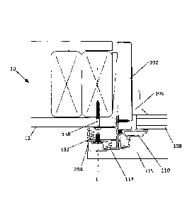
Improvements are
desired.
SUMMARY
[0003] According to one aspect of the present disclosure, an object is to
provide a window
assembly for mounting within an opening of a building structure, the window
assembly
comprising:
(a) a base frame assembly supporting at least one window pane and being
configured
for insertion into an opening in a wall, the base frame assembly defining an
outer
perimeter;
(b) an accessory support frame assembly being connected to and supporting the
base
frame assembly, the accessory support frame including a plurality of apertures
located laterally beyond the base frame outer perimeter, the plurality of
apertures
being configured for receiving a first plurality of fasteners extending into
the
building structure to secure the accessory support frame to the building
structure;
(c) an exterior accessory frame assembly connected to the accessory support
frame via
a second plurality of fasteners such that an interior facing surface of the
exterior
1
Date Recue/Date Received 2022-01-28
accessory frame overlaps with an exterior facing surface of the accessory
support
frame to cover the plurality of apertures and the first plurality of
fasteners;
(d) wherein the accessory support frame assembly plurality of apertures open
into an
internal cavity, the apertures being configured to allow ones of the first
plurality
of fasteners to be inserted into the internal cavity, wherein each of the
second
plurality of fasteners being engaged with one of the plurality of apertures to
secure
accessory frame members to the accessory support frame, wherein at least one
of
the first plurality of fasteners is aligned with at least one of the second
plurality of
fasteners along a common longitudinal axis, wherein the first plurality of
fasteners
are screws, wherein the second plurality of fasteners are one of push-in type
clips
and friction-type fasteners, wherein each of the second plurality of fasteners
is
provided with a shank and a head, and wherein the exterior accessory frame
includes at least one frame member having a longitudinal slot configured to
slidingly receive the fastener head to allow each of the second plurality of
fasteners to be aligned with a corresponding aperture in the accessory support
frame.
[0003a] According to another aspect of the present disclosure, an object is to
provide a modular
window assembly kit for mounting within an opening of a building structure,
the modular
window assembly kit comprising:
(a) a base frame assembly supporting at least one window pane and being
configured
for insertion into an opening in a wall, the base frame assembly defining an
outer
perimeter;
(b) an accessory support frame assembly being connected to and supporting the
base
frame assembly, and including a plurality of apertures located laterally
beyond the
base frame outer perimeter, the plurality of apertures being configured for
receiving a first plurality of fasteners extending into the building structure
to
secure the accessory support frame to the building structure;
(c) a plurality of exterior accessory frame assemblies, each being connected
to the
accessory support frame via a second plurality of fasteners such that an
interior
facing surface of the exterior accessory frame overlaps with an exterior
facing
surface of the accessory support frame to cover the plurality of apertures and
the
la
Date Recue/Date Received 2022-01-28
first plurality of fasteners, each of the plurality of exterior accessory
frame
assemblies having a cross-sectional profile that is different from at least
one other
exterior accessory frame assembly cross-sectional profile;
(d) wherein the accessory support frame assembly plurality of apertures open
into an
internal cavity, the apertures being configured to allow ones of the first
plurality
of fasteners to be inserted into the internal cavity, wherein each of the
second
plurality of fasteners being engaged with one of the plurality of apertures to
secure
accessory frame members to the accessory support frame, wherein at least one
of
the first plurality of fasteners is aligned with at least one of the second
plurality of
fasteners along a common longitudinal axis, wherein the first plurality of
fasteners
are screws, wherein the second plurality of fasteners are one of push-in type
clips
and friction-type fasteners, wherein each of the second plurality of fasteners
is
provided with a shank and a head, and wherein the exterior accessory frame
includes at least one frame member having a longitudinal slot configured to
slidingly receive the fastener head to allow each of the second plurality of
fasteners to be aligned with a corresponding aperture in the accessory support
frame.
10003b1 According to another aspect of the present disclosure, an object is to
provide a window
assembly for installation into an opening of a building structure, the window
assembly
comprising:
(a) a window assembly including a window pane extending along a first plane;
(b) a base frame supporting the window assembly, the base frame having an
outer
surface orthogonal to the first plane and defining an outer perimeter;
(c) a support frame connected to the base frame and extending away from the
outer perimeter in a direction parallel to the first plane, the support frame
including interior and exterior portions being parallel to the first plane and
defining an internal cavity therebetween;
(d) an accessory frame connected to the support frame;
(e) a plurality of first fasteners securing the support frame interior portion
to the
building structure, the first fasteners extending in a direction orthogonal to
the
first plane;
lb
Date Recue/Date Received 2022-01-28
(f) a plurality of second fasteners securing the accessory frame to the
support
frame exterior portion the plurality of second fasteners being separately
formed
from the accessory frame and support frame; and
(g) wherein the accessory frame conceals the interior cavity, the plurality of
first
fasteners, and the plurality of second fasteners such that heads of the first
fasteners are located between the interior and exterior portions of the
support
frame.
[0003c] According to another aspect of the present disclosure, an object is to
provide-a window
assembly for installation into an opening of a building structure, the window
assembly
comprising:
(a) a window assembly including a window pane extending along a first plane;
(b) a base frame supporting the window assembly, the base frame having an
outer
surface orthogonal to the first plane and defining an outer perimeter;
(c) a support frame connected to the base frame and extending away from the
outer
perimeter in a direction parallel to the first plane, the support frame
including
parallel interior and exterior portions defining an internal cavity
therebetween, the
support frame defining one or more mounting locations, at the interior
portion,
through which fasteners can extend to secure the support frame to the building
structure;
(d) an interior trim assembly connected directly to the base frame; and
(e) an accessory frame connectable to the support frame at the exterior
portion with
a plurality of fasteners separately formed from the accessory frame and the
support frame, the accessory frame, when connected to the support frame,
concealing the internal cavity and the one or more mounting locations from
view
from an exterior side of the window assembly.
[0003d] According to another aspect of the present disclosure, an object is to
provide-a method
of installing a window assembly comprising:
(a) providing a base frame including a plurality of base frame
members that
form a frame retaining at least one window pane extending along a first
plane;
lc
Date Recue/Date Received 2022-01-28
(b) providing an accessory support frame including interior and exterior
portions being parallel to the first plane and defining an internal cavity
therebetween;
(c) connecting the accessory support frame to the base frame;
(d) inserting the assembled base frame and accessory support frame into an
opening in a wall of a building structure;
(e) attaching the accessory support frame to the building structure with a
first
plurality of fasteners;
(f) selecting an exterior accessory frame from a plurality of differently
shaped
exterior accessory frames; and
(g) attaching the selected exterior accessory frame to the accessory
support
frame exterior portion via a second plurality of fasteners, separately formed
from the
accessory support frame and the exterior accessory frame, such that the
exterior accessory
assembly conceals the internal cavity, the first plurality of fasteners and
the second
plurality of fasteners once the exterior accessory assembly is connected to
the base frame
assembly.
[0003e] Other possible aspect(s), object(s), embodiment(s), variant(s) and/or
advantage(s) of the
present disclosure, all being preferred and/or optional, are briefly
summarized hereinbelow.
[0004] For example, window assemblies and methods for making window assemblies
are disclosed
herein. In one aspect, the window assembly can include a base frame assembly,
an accessory
support frame assembly, and an exterior accessory frame assembly. The base
frame assembly can
include a plurality of base frame members that form a frame that supports at
least one window
pane. The accessory support frame assembly can be connected to the base frame
assembly and
can be attached to a wall structure via a first plurality of fasteners such
that the accessory support
frame supports the base frame. The exterior accessory frame assembly can
id
Date Recue/Date Received 2022-01-28
CA 02902769 2015-08-31
include a plurality of accessory members that form a frame. Each of the
accessory members can
be connected to the base frame assembly via a second plurality of fasteners.
In one example, the
accessory members conceal the first plurality of fasteners once the exterior
accessory assembly is
connected to the base frame assembly.
[0005] In one example, a modular window assembly kit is provided, wherein
the accessory
support frame is defined as having an interior portion and an exterior
portion. In one aspect, a
first mounting feature is provided and located proximate the interior portion
of the accessory
support frame, wherein the first mounting feature connects the accessory
support frame to the
building structure. The kit can also include a plurality of exterior accessory
frame assemblies,
wherein an exterior profile of each exterior accessory frame assembly is
different from at least
one other exterior accessory frame assembly exterior profile. A second
mounting feature can
also be provided and located proximate the exterior portion of the base frame
assembly, wherein
the second mounting feature is constructed and arranged to connect the
accessory support frame
assembly to one of the plurality of exterior accessory frame assemblies.
[0006] A method of installing a window assembly is also described herein.
One step of the
method can include providing a base frame assembly including a plurality of
base frame
members that form a frame retaining at least one window pane. Another step can
be providing
an accessory support frame and connecting the accessory support frame to the
base frame. The
assembled base frame and accessory support frame can then be inserted into an
opening in the
wall of a building structure. The assembly can be attached to the building
structure via a first
plurality of fasteners that are engaged with the accessory support frame. In
one example, the
base frame assembly is not directly attached to the building structure with
fasteners or by other
means. In yet another step, an exterior accessory frame assembly is selected,
wherein the
exterior accessory frame assembly includes a plurality of accessory members
that form a frame.
The method can also include attaching the exterior accessory frame assembly to
the accessory
support frame via a second plurality of fasteners such that the exterior
accessory assembly
conceals the first plurality of fasteners once the exterior accessory assembly
is connected to the
base frame assembly.
2
CA 02902769 2015-08-31
DESCRIPTION OF THE DRAWINGS
[0007] Non-limiting and non-exhaustive embodiments are described with
reference to the
following figures, which are not necessarily drawn to scale, wherein like
reference numerals
refer to like parts throughout the various views unless otherwise specified.
[0008] Figure 1 is a perspective view of a window assembly having features
that are
examples of aspects in accordance with the principles of the present
disclosure.
[0009] Figure 2 is a cross-sectional view of the window assembly of Figure
1 through the
accessory support frame assembly and without an exterior accessory frame
installed.
[0010] Figure 3 is a cross-sectional view of the window assembly of Figure
1 through the sill
nose.
[0011] Figure 4 is a cross-sectional view of the accessory support frame
assembly of the
window assembly shown in Figure 1.
[0012] Figure 5 is a cross-sectional view of a first exterior accessory
frame assembly
configured for attachment to the accessory support frame assembly of the
window assembly
shown in Figure 1.
[0013] Figure 5A is a cross-sectional view of an alternative arrangement of
the first exterior
accessory frame assembly shown in Figure 5.
[0014] Figure 6 is a cross-sectional view of the window assembly shown in
Figure 1 with the
first exterior accessory frame of Figure 5 installed.
[0015] Figure 6A is a cross-sectional view of the window assembly shown in
Figure 1 with
the first exterior accessory frame of Figure 5A installed.
[0016] Figure 7 is a cross-sectional view of a second exterior accessory
frame assembly
configured for attachment to the accessory support frame assembly of the
window assembly
shown in Figure 1.
3
CA 02902769 2015-08-31
[0017] Figure 8 is a cross-sectional view of the window assembly shown in
Figure 1 with the
second exterior accessory frame of Figure 7 installed.
[0018] Figure 8A is a cross-sectional view of the window assembly shown in
Figure 1 with a
modified version of the assembly configuration shown in Figure 8.
[0019] Figure 8B is a cross-sectional view of the window assembly shown in
Figure 1 with a
modified version of the assembly configuration shown in Figure 8A.
[0020] Figure 9 is a cross-sectional view of a third exterior accessory
frame assembly
configured for attachment to the accessory support frame assembly of the
window assembly
shown in Figure 1.
[0021] Figure 10 is a cross-sectional view of the window assembly shown in
Figure 1 with
the third exterior accessory frame of Figure 9 installed.
[0022] Figure 11 is a cross-sectional view of the window assembly shown in
Figure 1 with a
modified version of an exterior frame.
[0023] Figure 12 is a cross-sectional view of a modular window assembly
with a modified
version of an exterior frame and accessory cover.
DETAILED DESCRIPTION
[0024] Various embodiments will be described in detail with reference to
the drawings,
wherein like reference numerals represent like parts and assemblies throughout
the several
views. Reference to various embodiments does not limit the scope of the claims
attached hereto.
Additionally, any examples set forth in this specification are not intended to
be limiting and
merely set forth some of the many possible embodiments for the appended
claims.
[0025] For the purpose of general illustration, Figure 1 shows a window
assembly 100
having a base frame assembly 102, a sash frame assembly 150 holding one or
more window
panes 108, and an interior trim assembly 105, as explained in detail below.
[0026] One aspect of the disclosure is base frame assembly 102. Base frame
assembly 102 is
the portion of window assembly 100 that is inserted into an opening of a wall
in a building or
4
CA 02902769 2015-08-31
other structure 10. The base frame assembly 102 provides the primary
structural support for
window assembly 100 and additionally provides a platform to which the other
components of
window assembly 100 can be mounted. As shown in FIG. 1, base frame assembly
102 defines a
frame having the shape of a rectangle or square from four base frame members.
Other shapes are
possible. For some types of windows, each of the four base frame members 102
may be cut from
a common base frame member stock such that they all have the same cross-
sectional profile.
Further, base frame member stock segments can be produced in lineal fashion
such that many
base frame members can be cut from a single length of stock. Thus, where
applicable, the use a
single lineal profile for all of the base frame members 102 results in a
reduction of frame part
types, part machining and assembly time. The base frame members 102 may be
constructed
from many materials, such as wood and extrudeable, pultrudeable or roll formed
materials,
including but not limited to aluminum, steel alloys, polyolefin polymers,
cellular PVC (polyvinyl
chloride or vinyl) polymers, cellulosic plastic composites, fiberglass
composites, polymeric
alloys or other extrudeable, pultrudeable and formable material. It is noted
that other
configurations for the base frame assembly 102 may be utilized without
departing from the
concepts herein.
[0027] The window assembly 100 can also be provided with a sash or glass
stop assembly
150 for securing a window pane 108 within the window assembly 100. In one
example, the sash
assembly is fixed with respect to the base frame assembly 102 such that the
window is fixed or
non-operable. In one example, the sash assembly 150 is provided as a moveable
assembly that
enables the window assembly 100 to be opened to the outdoors, where desired.
[0028] The sash assembly 150 can include an interior sash frame assembly
106 and an
exterior sash frame assembly 110 are provided that cooperate with the base
frame assembly 102
to secure the window pane 108. The interior sash frame assembly 108 is formed
from individual
frame members while the exterior sash frame assembly 110 is formed from
individual frame
members. As shown, the interior sash frame members are secured to
corresponding base frame
members 102 by fasteners, such as nails or screws. The exterior sash frame
members are also
secured to the corresponding base frame members 102 by fasteners 112, such as
by screws 112.
It is noted that other configurations for the sash assembly may be utilized
without departing from
the concepts herein.
CA 02902769 2015-08-31
[0029] The window assembly 100 may also be provided with an accessory
support frame
assembly 114 formed from individual frame members that form the frame assembly
114. In one
embodiment, and as shown at Figure 1, the accessory support frame assembly 114
can include
three frame members which form a frame with a structural sill nose 115 at the
bottom of the
window assembly 100. However, a sill nose 115 is not required for all
applications and a frame
can be formed entirely from the support frame members 114. For ease of
reference, the frame
members of the accessory support frame assembly 114 and sill nose 115 can be
referred to herein
as a frame member 114x. The accessory support frame assembly 114 is for
providing an
installation base to support a variety of differently styled exterior
accessory frame assemblies
104 that can be used depending upon application and the desired architectural
style for the
window assembly 100. As will be appreciated by one skilled in the art, the
disclosed accessory
support frame assembly 114 forms a portion of the exterior cladding of the
window assembly
100.
[0030] As most easily seen at Figures 2 and 3, the frame members 114x and
sill nose 115 are
attached to respective base frame members 102x via fasteners, such as screws
112. In one
example, the frame members 114x are attached to the building structure 10 via
fasteners 118,
such as screws 118 extending into one or more studs 11A or 11B. In the
embodiment shown, the
frame members 114x and sill nose 115 are secured to both the base frame
assembly 102 and the
building structure 10 via a plurality of fasteners 112, 118, respectively. In
one example, the
fasteners 112 secure the base frame assembly 102 to the support frame assembly
114 and the
fasteners 118 function to secure the entire window assembly 100 to the
building structure 10. In
such an example, the base frame assembly 102 can be further secured to the
building structure 10
with additional fasteners. Alternatively, the base frame assembly 102 can rely
completely on the
connection to the support frame assembly 114 for structural support with no
fasteners directly
securing the base frame assembly 102 to the building structure 10. In one
embodiment, the
corresponding members of the base frame assembly 102 and the support frame
assembly 114 are
formed as singular, integral components such that fasteners 112 are not
required.
[0031] As most easily seen at Figure 4, each of the frame members 114x has
an interior
portion 120 and an exterior portion 122 that are separated by an internal
cavity 124. As shown,
the interior portion 120 and fin 116 are adjacent to the building structure 10
and operate to align
6
CA 02902769 2015-08-31
the support frame assembly 114 to the building structure 10. In one aspect,
the exterior portion
supports the exterior accessory frame assemblies 104. Fins 128 and 130 are
also shown as being
provided to aid in aligning and/or securing the support frame members 114x
with the exterior
sash frame members 110x.
[0032] In one aspect, the exterior portion 122 can be provided with a
plurality of apertures
126. Apertures 126 can be configured to allow for fastener 118 to pass through
the exterior
portion 122 and into the internal cavity 124 of the frame members 114x such
that the fasteners
118 can secure the interior portion 120 to the building structure 10. The
interior portion 120 may
also be provided with an aperture aligned with aperture 126 such that fastener
118 does not have
to penetrate the interior portion 120 during installation. As explained
further, the apertures 126
also provide a mounting location for fasteners 132 associated with the
accessory frame 104,
resulting in the fasteners 132 and fasteners 118 being aligned along a common
longitudinal axis
L. It is noted that any number of apertures 126 can be provided, for example a
number of
apertures that exceeds the number of fasteners 132 such that an installer can
choose one of a
number of regularly spaced apertures 126.
[0033] Referring to Figures 5 and 6, a first example of an exterior
accessory frame 104 is
presented. As shown, accessory frame 104 can be mounted to the accessory
support frame 114
to provide a durable and aesthetically pleasing exterior appearance for the
window assembly 100.
The accessory frame 104 may include a plurality of accessory members 104x. In
one example,
four accessory members 104x are provided that together form a rectangular or
square frame. The
accessory frame 104 may also include three accessory members 104x, and in
conjunction with a
structural sill nose 115, form a frame, as shown in Figure 3.
[0034] Still referring to Figures 5 and 6, the accessory cover member 104x
includes a main
body 160 having an exterior surface 162 that can be used to form a 31/2 inch
frame with a stepped
appearance. As shown, the main body 160 has first interior surface 162 that
engages with a first
surface 122a of the exterior portion 122 of the frame member 114x. The main
body 106 has a
second interior surface 164 that engages and overlaps with a second surface
122b of the exterior
portion 122 of the frame member 114x to ensure a continuous exterior
appearance between the
frame member 114x and the cover member 104x. This configuration is
advantageous as the
7
CA 02902769 2015-08-31
window assembly 100 is designed such that both the frame members 114x and the
cover
members 104x are visible from the exterior, as are the exterior sash assembly
members 110x.
The main body also has a side edge portion 166 that engages with an exterior
surface 12 of the
building structure 10. In one aspect, the side edge portion 166 is provided
with a canted portion
166a that aids in attachment of the accessory cover to the siding by placing a
fastener through the
cover wall in this area. Canted portion 166a also forms a pocket for fastener
119 to allow for
brick or siding installation without interference from fastener 119 or a
related flange.
[0035] Referring to Figures 5A and 6A, a slightly modified version of the
accessory frame
104 is shown in which the main body side edge portion 166 is provided with a
support leg 166b
extending from the canted portion 166a. In this configuration, both the
support leg 166b and
canted portion 166a engage with the exterior surface 12 of the building
structure 10 to support
the side edge portion 166. This additional support more easily enables an
additional fastener 119
to be installed through the canted portion 166a and into the stud 11B or
another portion of the
building structure 10. As can be readily seen at Figure 6A, the fastener 119
is attached at an
angle such that the fastener 119 is non-orthogonal to the exterior surface 12
and non-parallel to
the fastener 118. This configuration allows for easier installation of the
fastener 119 by
providing a direct line of sight for a drill or screwdriver while also
ensuring that the head of the
fastener 119 is obscured by the main body when viewed directly from the front.
It is noted that
fastener 119 can also be used in the canted portion 166a for the configuration
shown in Figures 5
and 6.
[0036] Referring to Figures 7 and 8, a second example of an exterior
accessory frame 204 is
presented. As shown, accessory frame 204 can be mounted to the accessory
support frame 114
to provide another option for a durable and aesthetically pleasing exterior
appearance for the
window assembly 100. It is noted that the accessory support frame 114 is the
same as the frame
114 shown in Figure 6, even though the profile of the accessory frame 204 is
different from that
for frame 104. As with frame 104, the accessory frame 204 may include a
plurality of accessory
members 204x. In one example, four accessory members 204x are provided that
together form a
rectangular or square frame. The accessory frame 204 may also include three
accessory
members 204x, and in conjunction with a structural sill nose 115, form a
frame, similar to the
8
CA 02902769 2015-08-31
configuration shown in Figure 3. It is noted that accessory frame members 204
may also be bent
or used with non-rectangular frames.
[0037] Still referring to Figures 7 and 8, the accessory cover member 204x
includes a main
body 260 having an exterior surface 261 that can be used to form a brick mould
frame. As
shown, the main body 260 has first interior surface 262 that engages with a
first surface 122a of
the exterior portion 122 of the frame member 114x. The main body has a second
interior surface
264 that engages and overlaps with a second surface 222b of the exterior
portion 122 of the
frame member 114x to ensure a continuous exterior appearance between the base
frame member
114x and the cover member 204x. This configuration is advantageous as the
window assembly
100 is designed such that both the frame members 114x and the cover members
204x are visible
from the exterior, as are the exterior sash assembly members 110x. The main
body 206 also has
a side edge portion 266 that is exposed or faces bricks or other facing
materials of the building
structure 10. It is noted that accessory frame members 204 may also be bent or
used with non-
rectangular frames.
[0038] Referring to Figure 8A, a modified version of the arrangement shown
in Figures 7
and 8 is shown, wherein the accessory support frame members 114 are integrally
formed with the
exterior sash assembly frame members 110. In such an embodiment, the
integrated structure can
be referred to as an exterior support frame 114A. The exterior support frame
114A also differs
in that the attachment mechanism by which the accessory frame 204 attaches to
the exterior
support frame 114A is changed to accept a barb-type fastener 132A. As shown,
the exterior
support frame 114A is provided with a channel 133 for receiving the fastener
132A, wherein the
channel 133 does not create an opening into the interior space 124 of the
frame 114A.
Alternatively, the channel 133 can be open such that fasteners 118 can be
installed through the
opening. In the embodiment shown, an installer can simply drill a hole through
the channel 133
in order to install a fastener 118. In such instances, the resulting hole will
still be covered by the
accessory frame 204, once installed.
[0039] Referring to Figure 8B, a modified version of the arrangement shown
in Figure 8A is
presented, wherein the members of the accessory frame 204 are provided with a
different
configuration of a channel 234A. As shown, the accessory frame 204 is provided
with a channel
9
CA 02902769 2015-08-31
234A that is configured generally similarly to channel 133. In such an
embodiment, a double
barb-type fastener 234A can be used which extends between channels 133 and
234A to
interconnect the frames 114A, 204A. As with the embodiment of Figure 8A, an
installer can
drill a hole through the channel 133 in order to install the fastener, in this
case fastener 132B. In
such instances, the resulting hole will still be covered by the accessory
frame 204A, once
installed.
[0040] Referring to Figures 9 and 10, a third example of an exterior
accessory frame 304 is
presented. As shown, accessory frame 304 can be mounted to the accessory
support frame 114
to provide yet another option for a durable and aesthetically pleasing
exterior appearance for the
window assembly 100. It is noted that the accessory support frame 114 is the
same as the frame
114 shown in Figures 6 and 8 even though the profile of the accessory frame
304 is different
from that for frame 104. As with frame 104, the accessory frame 304 may
include a plurality of
accessory members 304x. In one example, four accessory members 304x are
provided that
together form a rectangular or square frame. The accessory frame 304 may also
include three
accessory members 304x, and in conjunction with a structural sill nose 115,
form a frame,
similar to the configuration shown in Figure 3.
[0041] Still referring to Figures 9 and 10, the accessory cover member 304x
includes a main
body 360 having an exterior surface 362 that can be used to form a stylized
frame. As shown,
the main body 360 has first interior surface 362 that engages with a first
surface 122a of the
exterior portion 122 of the frame member 114x. The main body has a second
interior surface
364 that engages and overlaps with a second surface 322b of the exterior
portion 122 of the
frame member 114x to ensure a continuous exterior appearance between the base
frame member
114x and the cover member 304x. This configuration is advantageous as the
window assembly
100 is designed such that both the frame members 314x and the cover members
304x are visible
from the exterior, as are the exterior sash assembly members 110x. The main
body 360 also has
a side edge portion 366 that is either exposed or faces bricks or other facing
materials of the
building structure 10.
[0042] Referring to Figure 11, an embodiment is shown in which the
accessory support
frame members 114, the exterior sash assembly frame members 110, and the
accessory frame
104 are provided as an integral structure. In such an embodiment, the
integrated structure can be
referred to as an exterior frame 114B. The exterior frame 114B can be attached
to the structure
with fasteners 118 which can be accessed through apertures 126. The apertures
126 can be
concealed by covers or inserts 127 since there is no accessory frame which
snaps over to cover
the apertures 126. As with the other shown embodiments, the window assembly
100 is secured
to the building structure 10 via fasteners 118 with fasteners 112 securing the
base frame
assembly 102 to the frame 114B, rather than having fasteners directly
attaching the base frame
assembly 102 to the building structure 10.
[0043] Referring to Figure 12, an embodiment is shown in which a modular
window assembly
10A is provided configured to accept the accessory frame 304. The attachment
of the support
frame assembly 114C to the building structure 10 and the attachment of the
accessory frame 304
to the support frame assembly 114 is the same as already described for the
example shown at
Figures 9-10, and therefore need not be described further here. However, in
this embodiment,
the window assembly 100 is of modular construction with a base frame assembly
102A provided
that is configured to accept various interior trim components 105 and the
exterior accessory
components 304. In this embodiment, a support frame assembly 114C is
configured to engage
the base frame assembly 102A in a snap fit-type arrangement rather than
relying on a connection
with fasteners 112. Additionally, the base frame assembly 102A is provided
with a nail fin 103
which enables the base frame assembly 112 to be secured to the building
structure 10 with
fasteners 118. The support frame assembly 114C is also configured such that
the window can be
supported via the support frame assembly 114C with fasteners 118 which are
then concealed by
accessory frame members 304. The configuration shown in Figure 12 is further
shown and
described in a US provisional patent application being concurrently filed with
this application
under attorney docket 04998.0006USP1 and entitled VERSATILE HYBRID WINDOW
SYSTEM, for example.
[0044] As explained previously, each provided accessory member 104x, 204x,
304x is
configured to be attached to a corresponding base frame member 102x of the
frame 102. As
shown, each accessory member 104x, 204x, 304x of the frame 104 has a
respective t-slot
arrangement 134, 234, 334 for holding a plurality of fasteners 132 equal to
the number of
apertures 126 provided along a member of the accessory support frame assembly.
The fasteners
11
Date Recue/Date Received 2022-01-28
CA 02902769 2015-08-31
132 are provided with a corresponding head 132a that is received by the
respective t-slot
arrangement 134, 234, 334. This configuration allows for the fasteners 132 to
be slid along the
length of the accessory member 104x, 204x, 304x within the slot 134, 234, 334
such that each
fastener can be easily aligned with the corresponding aperture 126. This
configuration also
allows for the fasteners 132 to be fully concealed from view once the
accessory members 104x,
204x, 304x are installed. The alternative arrangements shown at Figures 8A and
8B may also be
used with any of the disclosed configurations.
[0045] In one example, the fasteners 132 are friction-type fasteners or
clip fasteners, such as
Christmas tree fasteners or push-in clips, respectively. As shown, the
fasteners 132 are provided
with a ribbed shank 132b that engages the material surrounding aperture 126 to
secure the
accessory member 104x, 204x, 304x to the base frame member 102x. As shown, the
ribbed
shank 132b has a larger dimension than the apertures 126 such that an
interference or friction fit
occurs when pressed into the aperture 126. After insertion, the individual
ribs on a Christmas
tree type fastener 132 expand beyond the opening size of the aperture 126 and
provide resistance
to the fastener 132 being pulled back through the aperture 126. Some of the
ribs may be
compressed against the shank 132b at the location of the aperture 126 which
provides additional
friction. The ribs may also be provided with an angle such that less force is
required to insert
the fastener 132 into the aperture 126 as compared to the force to remove the
fastener 132 from
the aperture. The fasteners 132 are also shown as having a conical or
triangular tip section 132c
to allow for easier initial alignment of the fastener with respect to the
aperture 126. The
fasteners 132 may also be formed as expansion type clips that compress as they
pass through the
aperture 126, and then expand to a dimension greater than that of the aperture
126 when more
fully depressed through the aperture 126. The alternative arrangements shown
at Figures 8A and
8B may also be used with any of the disclosed configurations.
[0046] In one aspect, each of the exterior accessory members 104x, 204x,
304x may be cut
from stock material such that they all have the same cross-sectional profile.
Further, stock
material can be produced in lineal fashion such that many exterior accessory
members can be cut
from a single length of stock. Thus, the use of a single lineal profile for
accessory members of
the frames 104, 204, 304 results in a reduction of frame part types, part
machining, and assembly
time. In the exemplary embodiment shown, each of the exterior accessory
members of the
12
CA 02902769 2015-08-31
frames 104, 204, 304 is a painted aluminum extrusion, but may be constructed
from other
extrudeable, pultrudeable or roll formed materials as well, including but not
limited to steel
alloys, polyolefin polymers, cellular PVC (polyvinyl chloride or vinyl)
polymers, cellulosic
plastic composites, fiberglass composites, polymeric alloys or other
extrudeable, pultrudeable
and formable material.
[0047] The exterior accessory members of the frames 104, 204, 304 can be
provided in many
other cross-sectional shapes and sizes and are not limited to the examples
presented herein. It is
also noted that the exterior accessory members can be provided with different
shapes within the
same window assembly. For example, the bottom accessory member can be formed
in the shape
of a sill nose, the top accessory member can be formed in the shape of a drip
cap or cornice, and
the side accessory members can be formed from any number of other desired
shapes, such as flat
or stepped trim pieces. Additionally, the frames 104, 204, 304 can be more
than three or four
sided and do not necessarily have to be rectangular in shape. Other shapes are
possible for the
frames, for example, circular, ovular, triangular, pentagonal, hexagonal, and
so on.
[0048] The window assembly 100 may also include additional trim pieces, for
example jamb
extenders and interior trim components. Jamb extenders function to extend the
width of the
base frame assembly as necessary to ensure that the base frame members and the
jamb extenders
extend the entire width of the rough opening for the window. The trim
components can be
provided in the form of head stops and sill stops. It is also noted that the
built up construction of
the exterior components including an accessory cover attachable to a support
frame more easily
lend themselves to bending for curved window applications, in comparison to
similarly shaped
profiles where the entire exterior is a single component. Large width profiles
are difficult to
bend as the internal structures are prone to collapse with the large resulting
difference between
inside and outside radii. However, the disclosed embodiments using separable
accessory covers
and support frames can be individually bent and then assembled to form a wider
assembled
profile.
[0049] The various embodiments described above are provided by way of
illustration only
and should not be construed to limit the claims attached hereto. Those skilled
in the art will
readily recognize various modifications and changes that may be made without
following the
13
CA 02902769 2015-08-31
example embodiments and applications illustrated and described herein, and
without departing
from the true spirit and scope of the disclosure.
14