Note : Les descriptions sont présentées dans la langue officielle dans laquelle elles ont été soumises.
CA 02903364 2015-09-01
WO 2015/004268
PCT/EP2014/064925
- 1 -
CLEANING ASSEMBLY FOR A HARVESTER
Field of the Invention
The present invention generally relates to a cleaning assembly for a
harvester, such as a
combine harvester, operable to clean a crop, while moving along a direction of
the crop flow
from an upstream entrance to a downstream exit.
Background of the Invention
In a combine harvester, after a crop has been cut, it is passed through a
thresher which acts
to separate the grain from the stalks or the straw. The straw is transported
to the back of the
harvester by means of straw walkers, while the grain and other crop particles
are dropped
onto one or more sieves. The material other than grain (hereafter further
abbreviated with
"MOG") comprises chaff, short straw and other particles that the thresher has
separated from
the longer straw stems. The one or more sieves are reciprocated while air is
blown upwards
through it. The shaking of the sieve(s) distributes the grain evenly over the
area of the
sieve(s) and conveys the grain and MOG towards the back of the harvester. The
grain that
drops through the sieve(s) is collected in a sieve box using a grain auger
(also called
collecting trough) from which it is transported to a grain tank.
In GB 2224423, a combine harvester is described having a grain collecting and
cleaning
apparatus having a lower sieve element and three vertically spaced and offset
upper sieve
elements. The apparatus comprises a blower having a main outflow and an
additional
channel. The outflow openings of the additional channel are so arranged that a
drop step
between a stepped base disposed under a threshing basket and the front upper
sieve
element as well as the region below and behind the front upper sieve element
are subjected
to an air current. The middle and rear upper sieve elements are acted on by an
air current
from the main outflow channel of the blower. The grains separated out at the
middle and rear
upper sieve elements and other admixtures pass to the lower sieve element and
are there
subjected to a repeated sieving operation. The separated grains fall from the
lower sieve
element onto a grain base, which extends obliquely and at the lower end of
which a grain
worm is arranged operable to convey the grains to an elevator conveyor mounted
laterally
beside the machine frame. The stock mixture, which has been separated in the
end region of
the rear upper sieve element and the lower sieve element and consists
predominantly of
CA 02903364 2015-09-01
WO 2015/004268
PCT/EP2014/064925
- 2 -
grain and short straw components, passes by way of a return base to a
transverse conveyor
worm, which conveys the stock mixture into a mixture elevator.
In this grain collecting and cleaning apparatus, the blower is thus located at
the upstream
end this apparatus. The disadvantage thereof is that air is directed to the
rear, but not
sufficient relative to the huge length. There is too much air in front and not
enough at the
rear. This means that the fan will blow grain and MOG with a strong air blast
towards the rear
and there MOG will fall through the cleaning sieve, as there is no wind.
Consequently, no
efficient use of the available surface for sieve activity is obtained.
In order to reduce that effect, one should increase the fan blast even more,
ensuring the
grain to be blown out of the combine. This however is a very unstable
cleaning, hard to
adjust, with a bad grain sample as a consequence. Trying to improve the grain
sample will
reduce the capacity and vice versa.
In US 4,531,528, a cleaning shoe arrangement is disclosed having a generally
horizontal and
planar receiving element, receiving material from the threshing and separating
sections and
conveying at least a portion of it rearwardly to a chaffer having a downstream
discharge edge
and offset rearwardly and downwardly from the receiving element. A sieve
immediately
below the chaffer receives material passing downwards through the openings of
the chaffer.
A blower mounted ahead of and somewhat below the chaffer and sieve provides a
rearwardly and upwardly directed air blast to the underside of those elements
to assist their
screening operation. Clean grain passing downwards through the sieve is
intercepted by a
forwardly and downwardly sloping floor which delivers it to a clean grain
auger. At least some
of the material carried rearwardly by the chaffer and sieve finds its way into
the tailings
auger. The receiving element further includes a foraminous portion having a
series of
conventional fingers extending at the downstream delivery edge thereof. A
deflector carried
by this receiving element extends laterally over its full width and extends
downwardly and
forwardly from adjacent this downstream edge. Closely spaced beneath and
extending
almost the full length of the sieve portion of the receiving element is a
grain pan. The blower
has suitable outlets so that air may be delivered rearwardly and upwardly to
the underside of
the main chaffer and the sieves, respectively, by a main duct and also
rearwardly and
upwardly onto the underside of the sieve portion of the receiving element by
means of a
forwardly directed duct cooperating with a deflector or scoop. A transversely
extending sheet
metal deflector portion is disposed so as to receive crop material passing
over the rearward
CA 02903364 2015-09-01
WO 2015/004268
PCT/EP2014/064925
- 3 -
edge of the grain pan. The deflector surfaces cooperate to control the
combined flow of grain
from the grain pan and the downstream section of the sieve portion so that it
passes well
forward of the main sieve assembly and is released approximately vertically
above a
transversely extending downwardly and rearwardly sloping portion of the trough
of the clean
grain auger.
By locating a fan in the middle, a well balanced wind distribution is ensured,
left to right, front
to rear.
The problem with this cleaning shoe arrangement however is that clean grain
from the
receiving element that is falling onto the grain pan and that is guided by
means of the
deflector surfaces towards the clean grain auger, being the major part of the
cleaned grain,
falls in front of the main duct of the blower. This reduces the efficiency of
the airflow and
increases grain loss.
Object of the invention
The invention thus seeks to provide a cleaning assembly for a harvester having
a well-
balanced air distribution, having an efficient airflow and at the same time
having a minimal
grain loss.
Summary of the Invention
According to a first aspect of the invention, there is provided a cleaning
assembly for a
harvester operable to clean a crop, while moving along a direction of the crop
flow,
comprising:
- a fan assembly comprising:
= a fan operable to rotate about a rotation axis transverse to the
direction of the
crop flow for generating a flow of air; and
= a first fan outlet and a second fan outlet operable to output the flow of
air
generated by the fan, the first fan outlet being arranged at an upstream side
of
the rotational axis and the second fan outlet being arranged at a downstream
side of the rotational axis;
- a first sieve assembly comprising at least one reciprocable sieve and
extending along
the direction of the crop flow, an upstream end of the first sieve assembly
being
arranged near the first fan outlet such that the flow of air output by the
first fan outlet
generally flows along the first sieve assembly along the direction of the crop
flow; and
CA 02903364 2015-09-01
WO 2015/004268
PCT/EP2014/064925
-4-
- a second sieve assembly comprising at least one reciprocable sieve
and extending
along the direction of the crop flow, an upstream end of the second sieve
assembly
being arranged near the second fan outlet such that the flow of air output by
the
second fan outlet generally flows along the second sieve assembly along the
direction
of the crop flow, the second sieve assembly further comprising a clean grain
auger
arranged below the second sieve assembly for receiving cleaned grain
therefrom,
wherein the first sieve assembly further comprises a further clean grain auger
arranged
below the first sieve assembly for receiving cleaned grain therefrom.
The advantage of arranging the further clean grain auger below the first sieve
assembly for
receiving cleaned grain therefrom is that the grain of the first cleaning does
not have to pass
anymore in front of the second fan outlet. This increases the efficiency of
the airflow and
decreases grain loss. This arrangement also prevents that grain passing in the
vicinity of this
second fan outlet is blown away, allowing an efficient use of the available
surface for sieve
activity.
A further advantage is that by locating the fan in between the two clean grain
augers, a well-
balanced wind distribution on both sieve areas is obtained.
Still a further advantage is that there is no need for a return system on the
first cleaning by
the first sieving assembly since the return of the first cleaning goes towards
the second
cleaning performed by the second sieving assembly. Clean grain of the first
cleaning goes to
the clean grain elevator, but not into the auger case, meaning earlier grain
evacuation.
In an advantageous embodiment of a cleaning assembly according to the
invention, the
further clean grain auger is arranged transverse to the direction of the crop
flow of the first
fan outlet.
In a favourable embodiment of a cleaning assembly according to the invention,
the further
clean grain auger is operable to receive cleaned grain from an inclined grain
return pan
arranged below the first sieve assembly.
In a preferred embodiment of a cleaning assembly according to the invention,
the further
clean grain auger is arranged below the air flow outputted at the first fan
outlet, and/or the
clean grain auger is arranged below the air flow outputted at the second fan
outlet.
CA 02903364 2015-09-01
WO 2015/004268
PCT/EP2014/064925
- 5 -
This has the advantage that the efficiency of the airflow is further
increased.
In an advantageous embodiment of a cleaning assembly according to the
invention, the first
and second sieve assembly comprises a plurality of reciprocable sieves.
In a favourable embodiment of a cleaning assembly according to the invention,
- the first sieve assembly comprises at least one reciprocable first upper
sieve(s) and
one reciprocable first lower sieve arranged below the first upper sieve(s);
and
- the second sieve assembly comprises at least one reciprocable second
upper sieve(s)
and at least one reciprocable second lower sieve arranged below the second
upper
sieve(s).
In a preferred embodiment of a cleaning assembly according to the invention,
- the first upper sieve(s) is (are) operable to reciprocate in counter-
phase with the first
lower sieve(s);
- the second upper sieve(s) is (are) operable to reciprocate in counter-
phase with the
second lower sieve(s); and
- the first upper sieve(s) is (are) operable to reciprocate in counter-
phase with the
second upper sieve(s).
More preferably, the first and/or second sieve assembly comprises two upper
sieves.
The plurality of sieves of the first and/or second sieve assembly are
preferably configured to
perform cascade cleaning in combination with the fan. This has the advantage
that a better
cleaning of the grain is obtained.
In a favourite cleaning assembly according to the invention, the cleaning
assembly
comprises a first grain pan located after the upper sieve of the first sieve
assembly and
providing a bridge for the grain MOG mixture to the second sieve assembly,
wherein the
cleaning assembly comprises a system for preblowing after the first grain pan.
This has the advantage that the lighter chaff already is blown away.
CA 02903364 2015-09-01
WO 2015/004268
PCT/EP2014/064925
- 6 -
In an advantageous cleaning assembly according to the invention, the cleaning
assembly
comprises one single shaker shaft operable to reciprocate the sieves.
Consequently, the driving of the sieves of the cleaning assembly is not
complex. The
cleaning assembly is easily optimizable for functional performance and sample
quality
(throwing angles, strokes, etc.) No extra hanger and rocker arms are
necessary.
In order to compensate the slope of the ground on which the harvester is
travelling, the
cleaning assembly according to the invention may comprise a side slope
compensating
system operable to vary the lateral movement of the sieves.
In order to compensate the slope of the ground on which the harvester is
travelling, the
cleaning assembly comprises a mechanism for moving the sieves in mutually
orthogonal
directions.
In case of longer rotors towards the rear, for more threshing capacity, in a
possible
embodiment of a cleaning assembly according to the invention, the cleaning
assembly
comprises a shaker plate located after the downstream end of and above the
first sieve
assembly and being operable to reciprocate against the direction of the crop
flow to drop
crop back in the area where the blast of the fan is highest between the first
and the second
sieve assembly.
According to a second aspect of the invention, there is provided a method of
operating the
cleaning assembly according to the invention as described above, wherein a
sieve control
system controls the setup of the operational input parameters of the first and
second sieve
assemblies.
Preferably, the sieve control system performs the step of receiving from
inputs and/or
sensors separated operational input parameters associated with the first and
second sieve
assembly, the operational input parameters comprising for the first and second
sieve
assembly at least one value representative of:
- the frequency of the shaking movement of the first and second sieve
assembly;
- the stroke of the shaking movement of the first and second sieve
assembly;
- the sieve opening.
Brief Description of the Drawings
CA 02903364 2015-09-01
WO 2015/004268
PCT/EP2014/064925
-7-
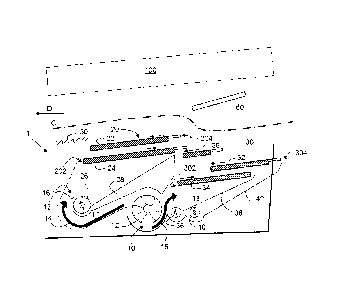
- Fig. 1 illustrates a front view of a schematic view of an embodiment of a
cleaning
assembly according to the invention;
- Fig. 2 illustrates a top view of the schematic view as shown in figure 1;
- Fig. 3 illustrates a schematic view of the linkages between the different
sieves to drive
and shake these sieves.
Detailed Description of Embodiment(s)
A cleaning assembly (1) according to the invention for a harvester operable to
clean crop
(not shown on the figures) while moving along a direction of the crop flow (C)
from an
upstream entrance (Cl) to a downstream exit (02), as shown in figures 1 and 2,
comprises
firstly a fan assembly (10). This direction of the crop flow (C) is opposite
to the driving
direction (D) of the harvester.
This fan assembly (10) comprises a fan (12) (also called blower) that is
operable to rotate
about a rotation axis (A) (see figure 2) transverse to the direction of the
crop flow (C) for
generating an air flow. The fan assembly (10) comprises a first fan outlet
(16) and a second
fan outlet (18) operable to output the flow of air (14, 15) generated by the
fan (12). The first
fan outlet (16) is arranged at an upstream side of the rotational axis (A) and
the second fan
outlet (18) is arranged at a downstream side of the rotational axis (A).
The cleaning assembly (1) according to the invention as shown in figures 1 and
2 also
comprises a first sieve assembly (20) and a second sieve assembly (30). The
upstream end
(202) of the first sieve assembly is arranged near the first fan outlet (16)
such that the air flow
from the first fan outlet (16) generally flows along the first sieve assembly
(20) and the
direction of the crop flow (C). The upstream end (302) of the second sieve
assembly (30) is
arranged near the second fan outlet (18) such that the air flow from the
second fan outlet
(18) generally flows along the second sieve assembly (30).
The embodiment of the cleaning assembly as shown in figures 1 and 2 has a
first sieve
assembly (20) comprising a first upper sieve (22) and a first lower sieve (24)
arranged below
this first upper sieve (22), while the second sieve assembly (30) comprises
two second upper
sieves (32, 36) and a second lower sieve (34) arranged below these two second
upper
sieves (32, 36). All sieves (22, 24, 32, 34, 36) are extending along the
direction of the crop
flow (C). As can be seen in figure 1, the different sieves (22, 24, 32, 34,
36) are configured to
perform cascade cleaning.
CA 02903364 2015-09-01
WO 2015/004268
PCT/EP2014/064925
- 8 -
The fan (10) provides a rearwardly and upwardly directed air blast to the
underside of the
different sieves (22, 24, 32, 34, 36) to assist their screening operation.
The different sieves (22, 24, 32, 34, 36) are reciprocable with respect to
each other in the
following way:
- the first upper sieve (22) is reciprocable in counter-phase with the
first lower sieve (24);
- the second upper sieves (32, 36) are reciprocable in counter-phase with
the second
lower sieve (34); and
- the first upper sieve (22) is reciprocable in counter-phase with the
second upper sieves
(32, 36).
In figure 3, the different linkages to drive the reciprocating movement of the
different sieves
(22, 24, 32, 34, 36) are shown. As can be seen therein, only one single shaker
shaft (51) is
necessary to reciprocate the sieves (22, 24, 32, 34, 36). It should however be
remarked that
instead of a single shaker shaft (51), also two or more shaker shafts can be
used to separate
the movement of the upper and the lower sieves (22, 24, 32, 34, 36). Also when
using two or
more shaker shafts, the movement of these upper and lower sieves (22, 24, 32,
34, 36) can
be controlled dependently or independently from each other.
As can be seen in figure 1, the second sieve assembly (30) comprises a clean
grain auger
(36) arranged below the second sieve assembly (30) and preferably below the
air flow
outputted at the second fan outlet (18). The clean grain auger (36) is located
below the air
flow outputted at the second fan outlet (18). Clean grain passing through the
sieves (32, 34,
36) of the second sieve assembly (30) is intercepted by an inclined grain
return pan (38)
arranged below the second sieve assembly (30) which delivers it to the clean
grain auger
(36).
The first sieve assembly (20) comprises a further clean grain auger (26)
arranged below the
first sieve assembly (20) and preferably below the air flow outputted at the
first fan outlet
(16). This further clean grain auger (26) is arranged transverse to the
direction of the crop
flow (C) at the first fan outlet (16). Clean grain passing through the sieves
(22, 24) of the first
sieve assembly (20) is intercepted by a further inclined grain return pan (28)
arranged below
the first sieve assembly (20) which delivers it to the further clean grain
auger (26). As can be
CA 02903364 2015-09-01
WO 2015/004268
PCT/EP2014/064925
- 9 -
seen in figure 1, this further clean grain auger (26) is located in a
deflector (13) of the air duct
(17) that is in connection with the first fan outlet (16).
As can be seen in figure 1, the cleaning assembly (1) also comprises a return
grain auger
(also called tailings auger) (40) operable for transporting tailings to a
separate threshing
cylinder. This return grain auger (40) is operable to receive cleaned grain
from a third
inclined grain return pan (42).
The cleaning assembly (1) according to the invention can comprise a first
grain pan (50)
located after the upper sieve (22) of the first sieve assembly (20). It's easy
to make this gran
pan larger towards the front in case of a drum and concave in front of the
rotors (not shown
on the figures).
The cleaning assembly (1) according to the invention optionally comprises a
side slope
compensating system (not shown on the figures) operable to vary the lateral
movement of
the sieves (22, 24, 32, 34, 36).
The cleaning assembly (1) also optionally comprises a mechanism for moving the
sieves (22,
24, 32, 34, 36) in mutually orthogonal directions to compensate the slope of
the ground on
which the harvester is travelling.
As is shown on figure 1, the cleaning assembly (1) according to the invention
optionally
comprises a shaker plate (60) located after the downstream end of the first
sieve assembly
(20) and above this first sieve assembly (20), more specifically the
downstream end (204) of
the first upper sieve (22). This shaker plate (60) is operable to reciprocate
against the
direction of the crop flow (C) to drop crop back in the area where the blast
of the fan (12) is
highest between the first and the second sieve assembly (20, 30). This is
particularly useful
in case of longer rotors (100) towards the rear for obtaining more threshing
capacity.
Although the present invention has been illustrated by reference to specific
embodiments, it
will be apparent to those skilled in the art that the invention is not limited
to the details of the
foregoing illustrative embodiments, and that the present invention may be
embodied with
various changes and modifications without departing from the scope thereof.
The present
embodiments are therefore to be considered in all respects as illustrative and
not restrictive,
the scope of the invention being indicated by the appended claims rather than
by the
CA 02903364 2015-09-01
WO 2015/004268
PCT/EP2014/064925
- 1 0 -
foregoing description, and all changes which come within the meaning and range
of
equivalency of the claims are therefore intended to be embraced therein. In
other words, it is
contemplated to cover any and all modifications, variations or equivalents
that fall within the
scope of the basic underlying principles and whose essential attributes are
claimed in this
patent application. It will furthermore be understood by the reader of this
patent application
that the words "comprising" or "comprise" do not exclude other elements or
steps, that the
words "a" or "an" do not exclude a plurality, and that a single element, such
as a computer
system, a processor, or another integrated unit may fulfil the functions of
several means
recited in the claims. Any reference signs in the claims shall not be
construed as limiting the
respective claims concerned. The terms "first", "second", third", "a", "b",
"c", and the like,
when used in the description or in the claims are introduced to distinguish
between similar
elements or steps and are not necessarily describing a sequential or
chronological order.
Similarly, the terms "top", "bottom", "over", "under", and the like are
introduced for descriptive
purposes and not necessarily to denote relative positions. It is to be
understood that the
terms so used are interchangeable under appropriate circumstances and
embodiments of
the invention are capable of operating according to the present invention in
other sequences,
or in orientations different from the one(s) described or illustrated above.