Note : Les descriptions sont présentées dans la langue officielle dans laquelle elles ont été soumises.
CA 02903453 2015-09-01
WO 2014/151090 PCT/US2014/024960
SYSTEMS AND METHODS FOR USING THREE-DIMENSIONAL LOCATION
INFORMATION TO IMPROVE LOCATION SERVICES
FIELD
[0001] Various embodiments relate to wireless communications, and more
particularly, to
networks, devices, methods and computer-readable media for acquiring three-
dimensional
location information, and using the acquired three-dimension location
information to locate users
and enhance their experience in relation to location-based services.
BACKGROUND
[0002] It is desirable to estimate the position (or "location") of a person in
a geographic area
with a reasonable degree of accuracy, and to associate that position with
nearby places, things
and services. Unfortunately, various techniques that estimate the position of
a user are often
expensive, slow or inaccurate. These shortcomings are pronounced in urban
environments,
where estimating the position of a person is difficult due to many challenges
that must be
overcome to deliver cost-effective and reliable position estimates. Even if
cheaper and more
reliable technologies are used, the scarcity of information regarding the
locations of places,
things and services, relative to the person, presents additional problems in
urban environments.
Accordingly, there is a need for improved techniques for estimating a position
of a person, and
for collecting assistance data that can be used with the position estimate to
connect that person to
a place, thing or service.
SUMMARY
[0003] Certain embodiments of this disclosure relate generally to networks,
devices, methods
and computer-readable media for acquiring and using three-dimensional location
information
associated with one or more receivers in transmitter network. Such networks,
devices, methods
and computer-readable media may identify estimated altitudes corresponding to
positions of the
one or more receivers in a building. A height for each of a plurality floors
in the building may be
1
CA 02903453 2015-09-01
WO 2014/151090 PCT/US2014/024960
identified based on the estimated altitudes. The identified floor heights may
then be used to
determine a location of a receiver in the building.
DRAWINGS
[0004] FIG. 1 depicts a positioning environment within which embodiments are
implemented.
[0005] FIG. 2 depicts aspects of receiver, transmitter and auxiliary
assistance system 270.
[0006] FIGs. 3A-3B illustrate a user interface at during operation of an auto-
rotation process.
[0007] FIG. 4 depicts an auto-rotation process.
[0008] FIG. 5 depicts a method for identifying a map corresponding to a floor
of a building.
[0009] FIG. 6 depicts positions of a receiver relative to a geo-fence
different times.
[0010] FIG. 7 depicts a method for confirming the accuracy of a position
estimate.
[0011] FIG. 8 depicts a method for crowd-sourcing altitude estimates to map
heights of floors.
DESCRIPTION
Overview of System
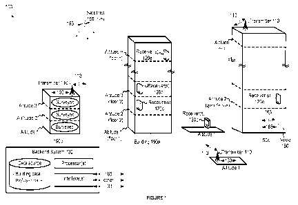
[0012] FIG. 1 illustrates a positioning environment 100 within which various
embodiments
disclosed herein may be implemented. The environment 100 includes a wide area
network of
synchronized transmitters 110 (also denoted herein as "beacons"), which are
depicted as
terrestrial, as well any number of receivers 120 configured to acquire and
track signals provided
from the transmitters 110, a network of satellites 150, or another network
node 160 (e.g.,
cellular, Wi-Fi, Ethernet, other communication network).
[0013] The environment 100 may further include a backend system 130 that
communicates
with various other systems, such as the transmitters 110, the receivers 120,
and the other
networks (e.g., the network node 160). The backend system 130 may include one
or more
processor(s), data source(s), interfaces and other components (not shown).
[0014] Components of the backend system 130 and the other systems (e.g.,
transmitters 110
and receivers 120) may be geographically distributed from one another in
different
neighborhoods, cities, counties, states, countries, or other types of regions,
such that the receiver
120 receives signals from the transmitters 110 in one location, and at least
some of the
processing related to those signals is carried out by the backend server 130
in another location. It
2
CA 02903453 2015-09-01
WO 2014/151090 PCT/US2014/024960
is noted that processing at one system (e.g., the transmitter 110, the
receiver 120, or the backend
system 130) may be initiated by signals received from another one of those
systems.
[0015] Various receivers 120a-e are depicted at various altitudes 1-n. Of
course, the
environment 100 may be configured to support more receivers and more altitudes
(or depths
below some reference altitude). Each receiver 120 may include a processor
(e.g., the processor
210 shown in FIG. 2) that determines position information based on signals
received from the
transmitters 110 or other networks (e.g., the satellites 150, the node 160).
Once known, the
position information may be used to estimate the position of the receiver 120
in terms of
Latitude, Longitude and Altitude (LLA).
[0016] Various techniques are used to estimate the position of an receiver,
including
trilateration, which is the process of using geometry to estimate a location
of the receiver using
distances (or "ranges") traveled by different "ranging" signals that are
received by the receiver
from different transmitters (or antennas when using a multi-antenna
configuration). If the time
of transmission of a ranging signal from a transmitter and the reception time
of the ranging signal
are known, then the difference between those times multiplied by speed of
light would provide
an estimate of the distance traveled by that ranging signal. These estimates
are often referred to
as "range measurements". In most cases, the range measurements are not equal
to the actual
ranges (i.e., shortest distances) between transmitters 110 and the receiver
120, mainly because
signals reflect off of objects (e.g., walls and other structures of buildings
190) that are disposed
between or near the transmitters 110 and the receiver 120. Consequently, the
estimate of the
receiver's position does not necessarily overlap the actual position.
[0017] The receivers 120 may receive signals from and/or send signals to the
transmitters 110,
the satellites 150 and the network node 160 via corresponding communication
links 113, 153 and
163. Communication connectivity between a receiver 120 and other systems
(e.g., the backend
system 130) may be carried out using wired means (e.g., Ethernet, USB, flash
RAM, or other
similar channels as is known or later developed in the art), or wireless means
(radio frequency,
Wi-Fi, Wi-Max, Bluetooth, or other wireless channels as is known or later
developed in the art).
[0018] The transmitters 110 may be configured to transmit signals that are
received by any of
the receivers 120, and to communicate with the backend system 130 via
communication links
133. In some embodiments, the transmitters 110 may transmit signals using one
or more
common multiplexing parameters¨e.g. time slot, pseudorandom sequence, or
frequency offset.
3
CA 02903453 2015-09-01
WO 2014/151090 PCT/US2014/024960
Each signal may carry different information that, once extracted, may identify
the transmitter
that transmitted the signal, ranging information that is used to measure a
distance to the
transmitter, and other information.
[0019] By way of example, various aspects that relate to signaling and
positioning of a receiver
based on signaling from transmitters, in a wide area network of transmitters
are described in co-
assigned U.S. Patent No. 8,130,141, issued March 6, 2012, entitled WIDE AREA
POSITIONING SYSTEM, and co-assigned U.S. Patent Application No. 13/296,067,
filed
November 14, 2011, entitled WIDE AREA POSITIONING SYSTEM, which are
incorporated
herein in their entirety and for all purposes, except where their content
conflicts with the content
of this disclosure.
[0020] FIG. 2 illustrates details of a receiver system 220, at which signals
from transmitters
may be received and processed to extract information used to compute an
estimated position of
the receiver system 220. The receiver system 220 may include any of a variety
of electronic
devices configured to receive RF or other signaling using wireless means
(radio frequency, Wi-
Fi, Wi-Max, Bluetooth, or other wireless channels as known or later developed
in the art), or
wired means (e.g., Ethernet, USB, flash RAM, or other similar channels as
known or later
developed in the art). Each receiver system 220 may be in the form of a
cellular or smart phone,
a tablet device, a PDA, a notebook or other computing device. It is noted that
User Equipment
(UE), Mobile Station (MS), User Terminal (UT), SUPL Enabled Terminal (SET),
Receiver (Rx),
and Mobile Device may be used to refer to the receiver system 220. As shown,
RF component
223 may control the exchange of information with other systems (e.g.,
satellite, terrestrial).
Signal processing may occur at a satellite component 224, or a terrestrial
component 225, which
may use separate or shared resources such as antennas, RF circuitry, and the
like. One or more
memories 222 may be coupled to a processor 221 to provide storage and
retrieval of data and/or
instructions relating to methodologies described herein that may be executed
by the processor
221. The receiver system 220 may further include one or more sensors 227 for
measuring
environmental conditions like pressure, temperature, humidity, acceleration,
direction of travel,
wind force, wind direction, sound, or other conditions. The receiver system
220 may further
include input and output (I/0) components 228 and 229, which may include a
keypad,
touchscreen display, camera, microphone, speaker, or others, which may be
controlled as known
4
CA 02903453 2015-09-01
WO 2014/151090 PCT/US2014/024960
in the art. It is noted that the receiver system 220 may be implemented by the
receivers 120
described herein, which may alternatively take on other forms as known by one
of skill in the art.
[0021] FIG. 2 further illustrates details of a transmitter system 210 at which
signals may be
generated and transmitted. The transmitter system 210 may include a processor
211 that carries
out signal processing (e.g., interpreting received signals and generating
transmission signals).
One or more memories 212 may provide storage and retrieval of data and/or
executable
instructions for performing functions described herein. The transmitter system
210 may further
include one or more antenna components (e.g., a satellite antenna or
terrestrial antenna) for
transmitting and receiving signals, a satellite RF component 214 for receiving
satellite signals,
from which location information and/or other information (e.g., timing,
dilution of precision
(DOP), or other) may be extracted, a terrestrial RF component 215 for
receiving signals from a
terrestrial network, and/or for generating and sending output signals, and an
interface 216 for
communicating with other systems. The transmitter system 210 may also include
one or more
environmental sensors 217 for sensing environmental conditions (e.g.,
pressure, temperature,
humidity, wind, sound, or other), which may be compared to such conditions as
sensed at a
receiver in order to estimate a position of the receiver based on similarities
and differences
between the conditions at the transmitter system 210 and the receiver. It is
noted that the
transmitter system 210 may be implemented by the transmitters described
herein, which may
alternatively take on other forms as known by one of skill in the art. Each
transmitter system
210 may also include various elements as are known or later developed in the
art for
sending/receiving signals to/from the antennas, including analog or digital
logic and power
circuitry, signal processing circuitry, tuning circuitry, buffer and power
amplifiers, and such.
[0022] Other components in FIG. 2 are described later in relation to
particular embodiments.
Overview of Various Embodiments
[0023] Various embodiments relating to the use of two-dimensional (2D) or
three-dimension
(3D) position estimates to improve location services may be implemented in the
environment
100. Certain embodiments, which are disclosed in further detail below,
include: 3D location
detection in outdoor and indoor environments; a user interface for providing a
map that auto-
rotates on a screen of a receiver depending on the heading of the receiver in
an environment;
cues provided to a user when navigating through an environment using a map
displayed on a
CA 02903453 2015-09-01
WO 2014/151090 PCT/US2014/024960
screen of a receiver; indoor map loading at an accurate floor level based on
the position estimate;
enabling/disabling applications based on position estimate;
enhancing/filtering estimates of a
receiver' s position (also referred to herein as a "position estimate" or
"position fix") using sensor
measurements (e.g., measurements of motion); estimating heights of floors,
things or places in a
building using crowd-sourced altitudes from position estimates; determining if
a receiver is
inside or outside of a building; using data corresponding to buildings in
urban environments
(e.g., address, reverse geo-code, height, number of floors, heights of floors,
atmospheric
conditions, information relating to places/things inside the building, and
other measurable or
quantifiable information); providing indoor and outdoor location services
relating to a user' s 3D
location, which may be particularly useful for a range of location services
(e.g., mapping of
unknown characteristics of environments, providing navigation, finding things,
sending targeted
advertising). Various enhancements to mobile applications using position
estimate are described
in further detail below.
User Interface (UI) with Map Application Auto-Rotate Feature
[0024] Various location services allow map applications to plot a user' s
current location on a
displayed map. Many of these map applications fail to help users navigate
outdoor or indoor
environments by providing mapped information along a heading direction of the
user. Maps
presented in known user interfaces are usually oriented in a fixed direction,
which can disorient a
user when the direction of the user' s heading does not align with the
orientation of the map.
Unfortunately, the user often must manually rotate his or her phone.
[0025] These problems are solved by tracking position estimates over time to
determine a
direction of travel, and/or by confirming or modifying that direction of
travel using sensed
motion. Once a direction of travel is known, an orientation of a map can be
auto rotated on a
screen (with suitable manual override to disable this feature) such that the
map orientation on the
screen is matched to the direction of heading. Motion may be sensed in various
ways, including
by inertial sensors (e.g., gyroscopes, accelerometers, compasses, and other
sensors configured to
determine orientation, direction of travel and speed of travel). Other
components may also be
used to "sense" motion relative to some local area transmission component at
known locations
(e.g., RFID sensors, local area beacons, and the like), where reception of
signals between a
receiver and transmission component(s), strength of signals and/or
trilateration using multiple the
6
CA 02903453 2015-09-01
WO 2014/151090 PCT/US2014/024960
signals from multiple transmission components can be used to determine the
direction of a user's
heading as the user approaches or moves away from those transmission
components.
Auto-Rotation
[0026] FIGs. 3A-B and FIG. 4 illustrate an auto-rotation process. FIGs. 3A-B
depict a screen
321 that displays maps 322a and 322b at two instances in time (e.g., Time 1
and Time 2). FIG. 4
illustrates a process for determining how to display the maps 322a-b at the
two times. An
estimate of a receiver's position at time t(n) is determined (410). A map tile
for the location of
the estimated position is loaded (420). Direction information of the map tile
(e.g., map
information direction layer) is used to orient the map tile in a set/pre-
determined orientation
(430). For example, the map tile may be oriented in a northern direction. A
heading at time t(n)
is determined (440). For example, a heading may be determined using position
estimates
between times t(n) to t(n-k), where k can be any number (e.g., 10 position
estimates). A
compass direction may also be used. Additional details regarding how a heading
may be
determined are provided later. A visual mark (e.g., an arrow) may be overlaid
on the map tile in
the direction of heading on the current position estimate relative to the
set/pre-determined
orientation of the map (450). The orientation of the screen may be determined
(e.g., landscape /
portrait) (460). Then, the map and the arrow are rotated in concert such that
the arrow is facing
the main orientation of the screen (470). Operations 410-470 may be repeated
for heading and
position estimates at subsequent times.
[0027] Of course, there are other ways to determine how to display the maps
322a-b. At the
first instance in time (Time 1), an estimate of a receiver's position and a
heading are determined.
The location of the position estimate in a geographic area is then determined,
and a map
corresponding to that location in the geographic area is identified.
Orientations of the map
relative to the heading and a screen of the receiver relative to heading are
then determined.
Finally, the map is displayed on the screen such that the orientations of the
map and the screen
align along the heading. The previous operations may be repeated for heading
and position
estimates at subsequent times (Time 2).
Heading
7
CA 02903453 2015-09-01
WO 2014/151090 PCT/US2014/024960
[0028] The heading may be determined using various techniques, where the
heading may be
provided to a map application that performs the auto-rotation method from
above. The heading
may be absolute (e.g., based on Northern, Eastern, Southern and Western
directions) or relative
(e.g., directionally relative to a past, current or future location on a map).
The heading may be
computed by a processor (e.g., the processor of the backend system 130 in FIG.
1, or the
processor 410 of FIG. 4), and various applications may access the computed
heading (e.g., via
SDK that an application developer may obtain from a network operator).
[0029] In one approach, consecutive position estimates are determined over a
period of time.
The heading may be computed by accumulating a set of position estimates (e.g.,
ten previous
position estimates) using corresponding pseudo-ranges to create a time-
sequenced location
vector. The changes in pseudo-ranges that correspond to the same transmitter
may be
determined, and relative changes may be evaluated (e.g., where decreases or
increases in range
towards a transmitter will result in a "direction vector" corresponding to
that transmitter). Since
the location of the transmitter is known, the processor (e.g., a position
engine) uses the location
of the current position estimate, along with the locations of the transmitters
and their direction
vectors, to determine an angle/direction of heading relative to each
transmitter. The headings for
each transmitter may then be combined to determine an overall heading.
Additional sensor
inputs may also be used (e.g., measurements from a compass, an accelerometer,
a gyroscope
and/or other inertial sensors) to fine tune the heading. Once the heading is
determined, a
message that includes the heading may be generated and sent to different
applications.
Cues to External Device
[0030] Mobile applications work well in stationary environments where the user
can give the
screen their full attention, however mobile applications do not work well when
the user is in
motion and taking cues from or otherwise reacting to the physical and virtual
environment
around the user. When a user is "on the move", it may be far better for the
user to get
complementary cues from the receiver (e.g., the receiver system 220 of FIG.
2). Such outputs
may include visual outputs (e.g., video or pictures via display, changing
states of lights), haptic
outputs (e.g., via vibration), and audio outputs (e.g., via speaker) at the
receiver¨e.g., from the
local outputs 229 shown in FIG. 2. Alternatively, such outputs could emit from
an auxiliary
assistance system 270 (see FIG. 2) as further described below.
8
CA 02903453 2015-09-01
WO 2014/151090 PCT/US2014/024960
[0031] As shown in FIG. 2, the receiver system 220 may be connected to an
auxiliary
assistance system 270 such as a watch, goggle, wrist band, or other device.
The connection may
be over a short range communication link such as Bluetooth, Zigbee, a cord or
other link, and
may be automatic or user-activated. Once connected, an application may be
launched on the
receiver system 220, and important cues may be sent to the auxiliary
assistance system 270
through respective interfaces 226 and 276. Alternatively, information may be
collected at the
auxiliary assistance system 270 (e.g., using sensors 277) and sent to the
receiver system 220 for
processing and cue generation.
[0032] One embodiment relates to a navigation application where the user gets
routed from
point A to point B. In this scenario, the receiver system 220 and auxiliary
assistance system 270
establish a connection, and the receiver system 220 launches a navigation
application at point A.
The receiver system 220 then generates signals that are intended to control
some output from the
receiver system 220 or the auxiliary assistance system 270 to provide
information/cues to the
user (e.g., direction from point A to B with respect to obstructions between
the points, location of
other users or places of interest along one or more potential pathways between
point A and point
B, and the like). Such cues may take the form of audio cues, visual cues or
haptic cues
indicating turns. This allows the user to navigate without looking at the
receiver system 220 or
the auxiliary assistance system 270. The auxiliary assistance system 270 may
also receive
indications about other receiver notifications (e.g., received call, email,
SMS).
Indoor Map Loading at Correct Floor Level
[0033] In accordance with certain aspects, an indoor location service allows
map applications
to plot a user's current location on an indoor map. However, indoor maps of
many buildings
have multiple floors and the user typically has to manually select the floor
level to view the
correct map of the floor in which they are present. Instead of manual
selection, an altitude of a
position estimate can be used to look up a floor level in a database that has
the mapping of each
floor level. Then, after identifying the floor level, an appropriate map
corresponding to that floor
may be loaded with appropriate manual overrides in case the user wants to see
the map of
another floor of the building. The building identity for the floor-level
matching may be
performed by reverse geocoding the position estimate that includes latitude
and longitude.
9
CA 02903453 2015-09-01
WO 2014/151090 PCT/US2014/024960
[0034] By way of example, FIG. 5 depicts a method for identifying a map
corresponding to a
floor level of a building. Initially, the latitude, longitude and altitude
(LLA) of a receiver is
determined (510). Based on the LLA, the building is identified from among
other buildings
(520). The building may reside at or near the latitude and longitude, and may
have a height that
is at least as high as the altitude. Optionally, a floor level of the building
is determined based on
the altitude (540). Each floor level in the building may be associated with a
particular height,
which can be looked up in a database. A map of a floor that corresponds to the
floor
level/altitude may be accessed and later displayed on an output of the
receiver (or auxiliary
assistance system 270) (550).
Enabling/Disabling Applications Based on Indoor 3D location
[0035] Three dimensional position estimates can be used by software
applications (e.g., MDM
services) of a receiver to control that receiver. For example, such
applications may
enable/disable specific functions based on a comparison of the receiver's
estimated position and
three-dimensional or two-dimensional geo-fences that specify rules that
control operations of the
receiver when it resides in the geo-fenced area. A remote server may send, to
each application
on the receiver, appropriate permissions to either be enabled or disabled
based on the position
estimate of the receiver relative to the geo-fence. It is understood that
other location technology
can also be used to track the estimated position of the receiver relative to
the geo-fence.
[0036] In an enterprise setting, specific access to data by certain
applications can be enabled or
disabled based on the receiver's location within the enterprise (e.g., a
particular area of a floor in
an office building). This can allow enterprises to ensure that sensitive data
may be accessed on
devices only when they may be within certain areas of the
office/floor/building. It can also be
used to turn off power-hungry applications when features of those applications
are unusable at
the user's current location. Similarly, entry into a geo-fenced area may
permit a receiver to
access information that is otherwise unavailable (e.g., sensitive, marketing,
or other information).
[0037] By way of example, FIG. 6 depicts positions of a receiver 620 relative
to a geo-fence at
Time 1, Time 2 and Time 3 in a building 690. As shown, the receiver 620 moves
from a first
altitude at Time 1, to a second altitude at Time 2 (at which a geo-fence is
established), and
eventually to a third altitude at Time 3. At Time 1 and Time 3, the receiver
620 may operate in a
CA 02903453 2015-09-01
WO 2014/151090 PCT/US2014/024960
first state (e.g., software application may run, data is not accessible). At
Time 2, the receiver 620
may operate in a second state (e.g., software application may not run, data is
accessible).
Filtering Position Estimates Using Other Sensor Input at a Receiver
[0038] In many location services, like GPS, one of two consecutive position
estimates may be
inaccurate. Occasionally, one of the consecutive position estimates can land
quite far off from
the receiver's location. In some cases, the two position estimates are
different even though the
receiver has not moved. Thus, it would be helpful to determine which of the
two position
estimates are inaccurate, which can be achieved using a software application
that uses input from
other sensors on the receiver to estimate if the receiver has actually moved a
distance separating
a first position estimate and a second position estimate. The distance may be
computed by
comparing latitude, longitude and altitude of the two position estimates.
Movement by the
receiver may be detected by any number of means that are known in the art,
including inertial
sensors that track motion in terms of direction and speed (e.g.,
accelerometers, gyroscopes and
others). The distance moved (as sensed by the sensors) can be compared to the
distance
separating the first and second position estimates. Of course, a similar
approach may be taken to
with more than two position estimates.
[0039] In one embodiment, a filters and thresholds are used to estimate if a
subsequent position
estimate is accurate. For example, when a threshold distance between
consecutive position
estimates is reached (e.g., 5 meters, 10 meters, 50 meters or some other
distance that is
dependent on precision required by a location service), a software application
checks
measurements from a sensor at the receiver to determine if the receiver moved,
and to determine
if the receiver moved the threshold distance or if the amount of movement is
within some
threshold value of the difference between the two position estimates. If
movement over the
threshold distance has occurred, or if the amount of movement is within the
threshold value of
the difference, then the second position estimate may be used as current
location of the receiver.
If the sensor input indicates that the movement over the threshold distance
has not happened, or
if the amount of movement is not within the threshold value of the difference,
then the second
position estimate may be discarded, and the current location may not be
changed/updated from
the first position estimate.
11
CA 02903453 2015-09-01
WO 2014/151090 PCT/US2014/024960
[0040] By way of example, FIG. 7 depicts a method for using sensed movement to
confirm
whether a position estimate is accurate. At a first instance in time, a first
estimate of a receiver' s
position is determined using a first set of range measurements from a network
of transmitters
(710). At a second instance in time, a second estimate the receiver's position
is determined using
a second set of range measurements from the network of transmitters (720). The
difference
between the first and second position estimates is measured in terms of
magnitude and direction
(730). In some embodiments, the measured distance is compared to a threshold
value of distance
to determine if the difference is greater than the threshold value. When the
distance is greater
than the threshold value, a measurement of distance moved between Time 1 and
Time 2 is
estimated using inertial sensors of the receiver by means known in the art
(e.g., tracking velocity,
which has magnitude and directional components) (740). In alternative
embodiments, the
comparison of the difference to the threshold value may be skipped, but the
sensed measurement
of distance moved between Time 1 and Time 2 is still estimated. The sensed
distance may be
compared the threshold value of distance, or to the difference between the
position estimates at
Time 1 and Time 2 (750). When the sensed distance is less than the threshold
value or not
within a predefined amount of distance from the measured difference, the
second position may
be ignored (760). When the sensed distance is greater than the threshold
value, or within the
predefined amount of distance from the measured difference, the second
position may be used
(770). Of course, a similar approach may be used to identify the first
position estimate as
inaccurate, and a similar approach may be used to identify one of three or
more position
estimates as inaccurate
Application to Crowd-Source Elevation to Floor-Level Data Mapping
[0041] Attention is now drawn to FIG. 1 to illustrate aspects of the following
disclosure related
to crowd-sourced mapping of floor levels in a building (e.g., the building
190a with n floors
designated by n altitudes). It is to be understood that discussion related to
mapping of floor
levels may extend to mapping of anything at different heights within a
building¨e.g., locations
of places like businesses, and locations of things like objects or
people¨where the heights are
associated with those places or things. It is also noted that similar mapping
may be made in
relation to latitude and longitude.
12
CA 02903453 2015-09-01
WO 2014/151090 PCT/US2014/024960
[0042] One approach to mapping heights is to manually measure each building to
find out the
height of each floor in a building. This is usually accomplished with a tape
measure or other
measurement tool. While this method may be accurate in capturing the elevation
to floor-level
mapping, it may be time consuming and labor intensive. An easier method is to
map individual
floor levels (or things/places) using crowd-sourced altitude computations
associated with
different positions of receiver(s). The altitudes may be stored in the data
source of the backend
system 130, and the processor of the backend system 130 may map particular
altitude values,
usually in meters (Height Above Ellipsoid or Mean Sea Level), to particular
floors of a building
190. Various methods for estimating the altitude of a receiver are known,
including those
methods discussed in U.S. Patent Application No. 13/296,067, filed November
14, 2011,
entitled WIDE AREA POSITIONING SYSTEM, which is incorporated herein in its
entirety and
for all purposes. In addition to altitude, estimates of the receiver's
latitude and longitude
coordinates may be recorded and used to identify the building within which the
receiver resides.
Alternatively, the building may be identified when the presence of the
receiver in the building is
detected (e.g., as it passes through a geo-fence of the building). Yet another
approach to
determine that the receiver is in a building is to compare the estimated
altitude to maximum
height of buildings, and ignore buildings with heights below that altitude.
One of skill in the art
will appreciate other approaches for determining that a receiver is in a
particular building.
[0043] In some embodiments, the user may be also asked to input, into the
receiver, the floor
level at which that user resides. The floor level may then be correlated to
the altitude that is
computed for that receiver. The building's reverse geocoded address may also
be determined
based on user input or based on the latitude and longitude of the estimated
position. Data
collected or otherwise determined at the receiver may be sent to a remote
database for storage
(e.g., the data source at the backend system 130), thus enabling later use of
the stored data.
[0044] In one embodiment, once at least two or more corroborating readings for
approximately
the same LLA are obtained, then a mapping of the altitude to a particular
floor level of a
particular building may be used for reference by other applications. The floor-
level-to-altitude
mapping data can also be given a confidence level based on the amount of
corroborating data.
[0045] In some embodiments, multiple altitude computations from the same
receiver or
multiple receivers may be determined over time (e.g., altitudes corresponding
to receivers 120a-c
in FIG. 1, or altitudes corresponding to the receiver 120 in FIG. 6). Groups
of computed
13
CA 02903453 2015-09-01
WO 2014/151090 PCT/US2014/024960
altitudes that that cluster together (e.g., within 1 meter of each other) may
corroborate an
assumption that those altitudes are associated with the same floor in a
building. Floor heights for
a building may then be inferred from the altitudes for different groups.
[0046] In some cases, altitudes for different groups may be compared to assign
altitudes to
particular floors. For example, if computed altitudes include 0 meters, 3
meters, 6 meters, 9
meters and 12 meters, as reported at the server from multiple receivers and
over multiple days
for the same building, it may be determined that the building includes at
least 5 floors with
separation of 3 meters between floors.
[0047] It may also be determined that certain heights corresponding to certain
floors have not
been collected, as may be determined when computed altitudes in ascending
order are not
separated by approximately the same distance (e.g., within 1 meter of the most
common distance
of separation between altitudes or an average distance of separation between
altitudes). Under
this scenario, heights and floors may be inferred by the shortest distance
separating two groups.
For example, if the computed altitudes include 0 meters, 3 meters, 6 meters, 9
meters, 15 meters
and 21 meters, then 12 and 18 meters may be assigned to fifth and seventh
floors, respectively,
and the computed altitudes may be assigned to the other floors (e.g., 0, 3, 6,
9, 15 and 21 meters
to floors 1, 2, 3, 4, 6 and 8). Using FIG. 1 as an illustration, altitudes of
the receivers 120a, 120b
and 120c in the building 190a may be mapped to floors n, 3 and 2,
respectively. However, the
altitudes for floors between floor 3 and floor n may not be known. Since the
difference between
floors 2 and 3 is known, and the distance between floors 1 and 2 may be
determined using
knowledge of street-level altitude to infer the altitude of the first floor,
the most common
separation between floors can be determined, and used to infer the heights of
floors between
floor 3 and floor n.
[0048] Over time, adjustments may be made as additional altitude computations
are received.
For example, if at a first instance of time, the computed altitudes include 0
meters, 6 meters, 12
meters and 18 meters, then it may be inferred that the building has at least
four floors that are
separated by at least 6 meters. However, once a computed altitude of 3 meters
is received, then
the assumed heights of floors may be adjusted to 3 meters, and the number of
floors may be set
at 7 floors or more. With reference to FIG. 1 as an illustration, using only
altitudes of the
receivers 120a and 120b may result in an initial assumption that each height
between the floors
in the building 190a is no more than the difference between altitude 3 and
altitude 1, instead of
14
CA 02903453 2015-09-01
WO 2014/151090 PCT/US2014/024960
the difference between altitude 2 and altitude 1 or altitude 3. However, once
the altitude of
receiver 120c is received, the initial assumption may be adjusted such that
the height between the
floors in the building 190a is based on the difference between altitude 2 and
altitude 1, and/or the
difference between altitude 2 and altitude 3.
[0049] Inaccurate assumptions of floor height may also be detected and
refined. If computed
altitudes include 0 meters, 3 meters, 7 meters, 9 meters and 12 meters, it may
be determined that
the 7 meter height of the third floor is inaccurate, and the height of the
third floor may be
adjusted to 6 meters since the average difference in heights between
neighboring floors is close
to 3 meters. One way of detecting an inaccurate height involves a calculation
of the average
separation between neighboring floor levels, or the most common separation
between
neighboring floors. The computed separation can then be compared against
separation between
different pairs of floors, and adjustments may be made when the separation
between two pairs of
floors is greater or less than the computed separation by some threshold
amount (e.g., 0.5
meters). Also, amounts of separation below and above a floor may be compared,
and the
average of those two amounts may be used to adjust the height of the floor so
that the separation
amounts below and above the floor are equal. Thus, the 7 meter height is
adjusted to 6 meters.
[0050] In some cases, a confidence level is associated with a height assigned
to a floor, or to
amounts of separation between floors. The confidence level can be related to
the number of
computed altitudes that have been collected for a particular range of heights,
where the greater
number of collected heights produces a higher level of confidence. Referring
back to the
previous example, the confidence level for 7 meters may be low when an amount
of heights that
have been collected fall below a threshold number, which may explain why the
height is 7
meters, not 6 meters. By comparison, the confidence levels for 3 meters and 9
meters may be
high when greater than the threshold number of heights have been collected.
Under such
circumstances, it may be determined that the 7 meter height of the third floor
is more likely to be
inaccurate than the other heights corresponding to other floors based on the
confidence levels for
each height/floor. Amounts of separation below and above the 7 meter height
may also be
associated with a low confidence value, at which point those amounts of
separation may be
weighted less than other amounts of separation when a weighted average of
separation between
neighboring floors is determined.
CA 02903453 2015-09-01
WO 2014/151090 PCT/US2014/024960
[0051] Of course, additional sources of information may be used, including
public records that
specify numbers of floors, and user information that associates a floor number
to a venue on that
floor (e.g., an employee or customer of a business on a particular floor). The
additional sources
of information may be used to further refine estimated heights of floors.
Also, using
corroborated groupings of altitudes is not required, and single altitude
estimates may be used.
[0052] By way of example, FIG. 8 depicts a method for crowd-sourcing altitude
estimates for
the purposes of mapping floors, things, or places in buildings to those
altitudes. Initially, groups
of estimated altitudes are identified (810). For example, a group may be
formed by estimated
altitudes that are within x units of each other (e.g., 1 meter). A height
corresponding to each
group may be identified (e.g., by performing a mathematical operation on the
group of estimated
altitudes, like computing an average or determining the most common altitude).
Each group
height may be mapped to different floors, things, or places in building (820).
The mapping may
relate different heights to each other. For example, a difference between
floors in a building may
be identified as the most common difference in height between consecutive
heights. Input that
identifies the floor level may alternatively obtained from a user of the
device, or by determining
that receivers in a group are within range of a local beacon that is located
at that floor level (e.g.,
the network node 160 in FIG. 1). Once heights of certain floors are known, the
heights of other
floors can be estimated when no group altitudes are available (830). For
example, the heights
may be determined based on height differences between other floors, where the
height difference
is projected up or down from mapped heights. Mapped heights may also be
adjusted (840). For
example, where a mapped height is not at an expected height, that mapped
height may be
adjusted to be closer to or at the expected height. The expected height may be
determined in a
similar manner as the estimated floors from operation 830.
3D Inside/Outside Location Detection
[0053] Using position estimates alone may make it difficult to
programmatically determine if
the receiver/user is within a building, outside a building, or at an adjacent
building. This is partly
because position estimates are often inaccurate by some amount of distance
from the true
position of a receiver. However, assistance information may be used along with
the position
estimate to determine a likelihood that the receiver' s true position is
inside a building, outside a
building, or in an adjacent building. The same is true of determining a
likelihood that the
16
CA 02903453 2015-09-01
WO 2014/151090 PCT/US2014/024960
receiver's true position is inside a particular area of a building, outside
that area, or in an
adjacent area. Such determinations are particularly advantageous for large
builds with many
areas (e.g., shopping malls), small neighborhoods, and the like. For
simplicity, discussion below
is provided in relation to building(s). However, the discussion extends to
area(s) within a
building, area(s) within a neighborhood, or area(s) within some other
localized area.
[0054] Certain embodiments use a method to determine if a receiver is within a
building (e.g.,
the receiver 120c inside the building 190a), if a receiver is just outside the
building (e.g., the
receiver 120d outside the building 190a), or if a receiver is in an adjacent
building (e.g., the
receiver 120e in the building 190c). The location may be determined based on a
current position
estimate of the receiver and assistance information associated with the
building(s), as accessed
from a data source (e.g., from the backend system 130).
[0055] Determining the location of the receiver, relative to a building or
buildings, may be
accomplished by the use of a SDK and API at the receiver. The SDK obtains the
current
position estimate of the receiver. The SDK uses a standard-defined API to send
the current
position estimate and, if available, a unique identifier of a detectable area
within a building (e.g.,
a venue, floor, and the like) to a remote server (e.g., the backend system
130). The remote server
responds to the SDK via the API in a standard data structure to indicate if
the position estimate is
within the building, outside the building, or at an adjacent building. Reverse
geocode
information corresponding to the building(s) may also be provided.
[0056] When a three-dimensional position estimate is sent to a remote server
via a standard
API, the remote server compares that position estimate against a set of pre-
built 3D geo-fences
for a building (e.g., maximum geographical boundaries of the building or areas
inside the
building in terms of latitude, longitude and altitude). By way of example, a
geo-fence at altitude
2 in building 190c is shown in FIG. 1. A programmable parameter related to a
relative distance
of the position estimate to the pre-built geo-fence can be used to determine
if the position
estimate is in the building (e.g., the building 190c), in an adjacent building
(e.g., the building
190a), or outside those buildings. Such a parameter may include a threshold
amount of distance
that is compared to the relative distance.
[0057] Relative distances from multiple beacons/geo-fences in neighboring
buildings may be
used to determine if a receiver is more likely to be in one of the buildings
or in between the
buildings. For example, if the position estimate is closer to a first geo-
fence in a first building
17
CA 02903453 2015-09-01
WO 2014/151090 PCT/US2014/024960
than a second geo-fence in a second building, then it may be determined that
the receiver is
within the first building. Or, if the position estimate is approximately
(e.g., within a few meters)
the same distance away from the first geo-fence and the second geo-fence, then
it may be
determined that the receiver is in between those buildings (i.e., outside of
those buildings). In
this way, relative distances between two buildings can be determined.
[0058] In alternative embodiments, height envelopes of buildings (or
accessible floors in
buildings) may be compared to the estimated altitude of a receiver to
determine if the receiver is
inside or outside that building. For example, if two buildings are adjacent to
each other, where a
first building is shorter than the altitude, and a second building is taller
than the altitude, it can be
determined that the receiver is in the second building. By way of another
example, if both
buildings are taller than the altitude, but the altitude corresponds to an
inaccessible area of the
first building (e.g., a secure floor), it is determined that the receiver is
in the second building.
[0059] By way of yet another example, an identifier received from a local area
network
associated with a particular venue (e.g., a coffee shop, a business, and the
like) can be used to
look up that network in a database, and then look up the building (or area of
a building) that
houses that venue. Similarly, an identifier received from a short-range
communication link
provided by a user device (e.g., a hot spot or other identifiable signal) can
be used to look up that
user device in a database, and then look up the building (or area of a
building) where that user
device is typically present, or identify where that user device is not
typically present.
[0060] Historical locations of the receiver may be tracked and associated with
particular
buildings or heights in areas of a city. The historical locations can be used
to determine how
likely the current location of the receiver is in a particular building/area.
For example,
knowledge that a receiver is regularly located in a building on certain days
and at certain times
can be used to identify that building as the most-likely location of the
receiver, from among other
nearby locations. Movements among buildings can also be tracked and used to
determine that
the receiver has exited the building through a geo-fence. Additionally,
knowledge of a user's
calendared events may be correlated to buildings and times, and then used to
determine whether
the user is indoors or outdoors based on the location and time of the event.
[0061] The determinations may be performed on the remote server, on the
receiver, or both.
The response may be in some coded form that conveys one of the following
relationships: "The
position estimate (or actual location) is within a first building-
address/name, confidence level";
18
CA 02903453 2015-09-01
WO 2014/151090 PCT/US2014/024960
"The position estimate (or actual location) is outside/near the first building
address/name,
confidence level"; and "The position estimate (or actual location) is in an
adjacent building
address/name, confidence level". The confidence levels may be related to the
relative
position/distance of the position estimate to the relevant pre-built geo-
fence(s), such that a higher
confidence level will be given when position/distance of the position estimate
is within some
maximum threshold distance from the pre-built geo-fence(s), or separated by
some minimum
threshold distance from the pre-built geo-fence(s).
[0062] It is noted that the above approaches can be similarly applied to
estimating a floor or
area, from among multiple floors or areas, at which a receiver likely resides.
Web-Based Services & Analytics Regarding Environmental and User Information
Web Service
[0063] Various embodiments operate in association with a multi-tier (e.g., 3-
tier) cloud-based
service. Other non-cloud based services may similarly be used. For example,
one component of
the cloud based service may include a data source (e.g., a building database
or database of
building information) built on a database software system such a as SQL-MySQL,
NoSQL-
Hadoop, or other technology. The data source may have a defined data
structure/schema that
identifies each building using, among other things, a building identifier, an
address,
latitude/longitude/altitude (LLA) coordinates, a LLA-based envelope of the
building, or other
unique identifier. The data may further identify the contents or other
characteristics of each
building¨e.g., floors, venues within the building, atmospheric conditions on a
per-time basis,
and other contents or characteristics. Other components of the cloud based
service may include:
middle-ware business-logic implementation to manipulate the data in the
building database and
to monitor access to the web service; and front-end interfaces to interact
with the building-
database and the middle-ware business logic.
Data
[0064] The building database may store various types of data. For example,
data may
represent an indoor map of every floor of a building including any sub-
structures or venues (e.g.,
stores within a mall, commercial or residence units in a high-rise building).
The data may map
19
CA 02903453 2015-09-01
WO 2014/151090 PCT/US2014/024960
(or otherwise associate) floor levels to altitudes, or ranges of altitudes
that correspond to
different floors of the building. For example, the value of the altitude may
be based on either
imperial or metric systems of measurement in either Height Above Ellipsoid
(HAE) or Mean Sea
Level (MSL) formats, or both.
[0065] The database may also store an RF-signature of every floor (or sections
of each floor).
The RF-signature can be obtained by either surveying the area of that floor
(e.g., as shown in the
building 190b of FIG. 1), or crowd-sourcing the RF signatures over a period of
time. The RF-
signature may characterize each available signal in that area based on
detectable signal
properties. For each area, the database may also store pseudoranges for each
signal, signal-to-
noise ratio or other indication of signal strength for each signal, and/or an
indication that the
signal is a multipath signal.
[0066] Data representing one or more pre-built 3D geo-fences for each
building, floor or
thing/place may be stored. Each geo-fence may be based on the geographic
perimeter of the
building, spaces within a building (e.g., store/shop within a mall, floor
space), or proximity to a
thing or place. For example, a geo-fence may designate a range of coordinates
along the
boundary of the geo-fence. In this manner, the geo-fences may be defined in
three dimensions.
A fourth dimension of time may also be used to indicate when a particular geo-
fence changes
one of its characteristics (e.g., for multipurpose areas, or areas that have
scheduled changes to an
associated characteristic like occupancy). With prebuilt geo-fences, whether a
particular position
coordinate (e.g., some or all of latitude, longitude, and altitude) falls
within or outside of physical
boundaries of a building, floor, or venue can be determined.
[0067] Accuracy of the data during collection or storage can be determined
using various
approaches (e.g., based on age, quality, relevance, correlation, and other
considerations). For
example, data may be tracked over time for changes, newly collected data may
be correlated to
stored data, the relevance or quality of data may be estimated and represented
as a stored
relevance or quality metric value, the age of data may be tracked and stored,
or other analysis
may be performed to evaluate the data before its use.
[0068] Of course, known mechanisms to add data to the database either manually
or
programmatically are contemplated.
Middleware
CA 02903453 2015-09-01
WO 2014/151090 PCT/US2014/024960
[0069] Middleware business logic may contain several features. For example,
the middleware
may have the ability to: process API requests from receivers; verify the
Developer API Keys and
take appropriate action if the key is valid or invalid; enforce business rules
on usage of the API;
and monitor the rate of usage of the database by the receiver on a per
receiver, per developer, per
user, or per key basis.
[0070] The middleware may also compare a position estimate corresponding to a
receiver in
the form of latitude, longitude, and latitude, or pseudo-ranges obtained from
the receiver, against
pre-built geo-fences to provide triggers such as "within a geo-fence",
"outside-a-geo-fence",
"number of times traversed a geo-fence", and others. The middleware may
determine and
provide such triggers to specify if an estimated position is within, outside
and adjacent to a
building. The middleware may include predictive software functions that can
estimate error
associated with an estimated position, any stored data or the estimated
position's relationship to
the stored data, and then assign a confidence to the presence of the receiver
within a building or
in a building adjacent to it.
[0071] The middleware may include filtering mechanisms to discount the
presence of a
device's estimated position within a building if the altitude component of
consecutive estimates
of the receiver's position is consistently (for a programmable period of time)
at a height where
the building has no floors, or where a user of the device is not authorized.
[0072] The middleware may include an ability to import altitude to floor-level
data and store it
into the building database. The middleware may further include an ability to
reverse geocode the
floor-level of a building based on the altitude in either HAE or MSL formats.
Front End
[0073] Front-end interfaces of the building data web service may contain
various features. For
example, the front end may include: an admin console user interface (UI) and
Admin-APIs with
role-based access that allows the data in the building database to be
manipulated; a set of defined
API methods with requisite access restrictions via developer keys to allow
customers/user to
programmatically access the information contained in the building database or
the results of the
computation performed by the middleware business logic layer/engine; a
customer account
portal to allow the users/customer to manage their accounts, billing, rate
limits and more; and
other features.
21
CA 02903453 2015-09-01
WO 2014/151090 PCT/US2014/024960
Indoor Map
[0074] An indoor map web service may include a specialized interface into the
building data
web service that allows the entire or portions of an indoor map corresponding
to a building or
group of buildings to be made available on a web browser or other application
(e.g., for E-911
dispatching, building management, enterprise mobility/service management).
In some
embodiments, an indoor map web service is integrated by a solutions provider
for the various
verticals such as E-911 consoles, building management software systems,
receiver management
systems, commercial LBS systems, independent developers and applications.
Analytics
[0075] A location analytics system may be configured to interface with the
building data web
service using its own multi-tier cloud server architecture. The location
analytics system may
contain various components, including: a location analytics database;
middleware business logic;
and front-end interfaces for interactions between users and the analytics
system.
Data
[0076] The location analytics database may store different types of data,
including: meta-data
about the buildings in the building database including elements such as
address, number of
tenants in the building, tenant information, tenant category, building
statistics and more;
temporal data about buildings (e.g., such as events happening in a building,
heat-mapping of
building); spatial data (e.g., climate/weather, geographical location, season,
demographic trend
and more); pre-built path information (e.g., which may string together meta-
data, temporal data
and spatial data for a set of buildings with its associated geo-fences to
create a "path" that
represents a reference lifestyle for a user type); lifestyle profile data
(e.g., specifying
demographic or interest information about users like a relationship relative
to other people like
being a mom, an occupation or role like student or engineer, an age group like
20-something, a
hobby or interest like being a sports fan or an outdoor enthusiast); user
profile data (e.g., gender,
age, friends, family); device characteristics (e.g., model, OS, operator);
historical path
information of individual assets/users with appropriate privacy protections
and non-identifiable
markers; historical location information about each device (e.g., based on the
device's unique
identifier); and others.
22
CA 02903453 2015-09-01
WO 2014/151090 PCT/US2014/024960
Middleware
[0077] The middleware business logic engine may implement several features,
including: an
ability to reverse geo-code locations within a building based on estimated
positions obtained
from a receiver using the location analytics database and the building
database; and
typecast/profile a user's behaviors based on their path information (e.g.,
where the user has
traveled with the receiver) and comparing it to pre-built path-profiles and
their own historical
path information with built-in filtering to minimize variance. The
typecast/profile of a user can
be based on that user's estimated position (or set of estimated positions over
time). It may be
used for a variety of applications, such as an ability to connect with an
advertisement network to
obtain and target highly relevant and hyper-local mobile advertisements, where
the level of
relevance may be obtained by the combining or correlating location analytics
(e.g., path/lifestyle
profile, building meta data, user profile, device characteristics and more). A
messaging platform
may be used to convey an advertisement and other notifications to the user's
receiver (e.g.,
pushed to a user based on user permissions).
Front End
[0078] The front-end interfaces of the building data web service may contain
several features,
including: an admin console UI and Admin-APIs with role based access that
allows the data in
the building database to be manipulated; a set of defined API methods with
requisite access
restrictions via developer keys to allow customers/user to programmatically
access the
information contained in the building database or the results of the
computation performed by the
middleware business logic layer/engine; a customer account portal to allow the
users/customer to
manage their accounts, billing, rate limits and more; and other features.
Example Methodologies
[0079] Functionality and operation disclosed herein may be embodied as one or
more methods
implemented by processor(s) at one or more locations. Non-transitory processor-
readable media
embodying program instructions adapted to be executed to implement the
method(s) are also
contemplated. The program instructions may be contained in at least one
semiconductor chip.
[0080] By way of example, not by way of limitation, method(s) may comprise:
identifying a
plurality of estimated altitudes corresponding to a plurality of historical
positions of the one or
23
CA 02903453 2015-09-01
WO 2014/151090 PCT/US2014/024960
more receivers in a building; and identifying a height for each of a plurality
floors in the building
based on the plurality of estimated altitudes.
[0081] Method(s) may further or alternatively comprise: identifying a first
set of estimated
altitudes that are within a threshold amount of distance from each other;
identifying a first height
that corresponds to the first set of estimated altitudes; and mapping the
first height to a first floor
of the building. In accordance with some aspects, the first height is based on
an average of each
estimated altitude in the first set of altitudes. In accordance with some
aspects, the threshold
amount of distance is 1 meter.
[0082] Method(s) may further or alternatively comprise: identifying a second
set of estimated
altitudes, from the plurality of estimated altitudes, that are within the
threshold amount of
distance from each other; identifying a second height that corresponds to the
second set of
estimated altitudes; and mapping the second height to a second floor of the
building.
[0083] Method(s) may further or alternatively comprise: identifying an
additional set of
estimated altitudes, from the plurality of estimated altitudes, that are
within the threshold amount
of distance from each other; identifying an additional height that corresponds
to the additional set
of estimated altitudes; and mapping the additional height to an additional
floor of the building
based on a first difference in height between the first height and the second
height.
[0084] Method(s) may further or alternatively comprise: determining a second
difference
between the additional height and the first height; determining a ratio of the
second difference to
the first difference; identifying a floor number of the first floor; and
determining a floor number
of the additional floor based on the ratio. Method(s) may further or
alternatively comprise:
mapping an additional height to an additional floor of the building based on a
difference in
height between the first height and the second height. Method(s) may further
or alternatively
comprise: dividing the plurality of estimated altitudes into sets of estimated
altitudes that are
within the threshold amount of distance from each other; identifying a total
number of the sets;
and determining a minimum number of floors in the building based on a total
number.
[0085] By way of example, not by way of limitation, method(s) may comprise:
determining a
first estimate of a receiver' s position in three dimensions; comparing the
first estimate of the
receiver' s position to a first geo-fence associated with a first building;
determining, based on the
comparison, a first relationship between the first estimated position and the
first building,
wherein the first relationship specifies whether the first estimated position
is within the first
24
CA 02903453 2015-09-01
WO 2014/151090 PCT/US2014/024960
building, outside of the first building, or within an adjacent building; and
determining a
confidence level related to the first relationship.
[0086] Method(s) may further or alternatively comprise: comparing the first
estimate of the
receiver' s position to a second geo-fence associated with a second building;
determining, based
on the comparison, a second relationship between the first estimated position
and the second
building, wherein the second relationship specifies whether the first
estimated position is within
the second building, outside of the second building, within the first
building, or within the
adjacent building; and determining a confidence level related to the second
relationship.
[0087] By way of example, not by way of limitation, method(s) may comprise:
determining a
first estimate of a receiver' s position; setting the current position of the
receiver as the first
estimate of the receiver' s position; determining a second estimate of the
receiver's position;
determining whether the second estimated position, relative to the first
estimated position,
indicates that the receiver has moved more than a threshold distance; after
determining that the
second estimated position, relative to the first estimated position, indicates
that the receiver has
moved more than a threshold distance, determining whether one or more sensors
of the receiver
indicate that the receiver actually moved more than the threshold distance;
setting, based on
determining that the one or more sensors of the receiver indicate that the
receiver moved more
than the threshold distance, the current position of the receiver as the
second estimate of the
receiver' s position; and maintaining, based on determining that the one or
more sensors of the
receiver indicate that the receiver did not move more than the threshold
distance, the current
position of the receiver as the first estimate of the receiver's position.
[0088] By way of example, not by way of limitation, method(s) may comprise:
determining a
first estimate of a receiver' s position; and disabling an application on the
receiver based on a
comparison of the first estimate of the receiver's position and a first set of
three-dimensional
position information corresponding to a first geo-fence inside a building.
Method(s) may further
or alternatively comprise: determining a second estimate of the receiver's
position; and
enabling the application on the receiver based on a comparison of the second
estimate of the
receiver's position and a second set of three-dimensional position information
corresponding to a
second geo-fence inside the building. In accordance with some aspects, the
application is
disabled to lower power consumption of the receiver. In accordance with some
aspects, the
application is disabled to prevent the receiver from accessing data from
inside the building.
CA 02903453 2015-09-01
WO 2014/151090 PCT/US2014/024960
[0089] By way of example, not by way of limitation, system(s) for collecting
and using data in
association with three-dimensional estimates of position that correspond to
one or more mobile
user devices may comprise: at least one data source that stores data
corresponding to one or more
buildings, wherein the data corresponding to each of the one or more buildings
specifies an
identifier, an address, latitude, longitude, an altitude of each floor, and a
map of each floor
corresponding to that building; and one or more processors that access the
data in association
with one or more requests from one or more mobile user devices.
[0090] In accordance with some aspects, the one or more processors verify one
or more
developer keys associated with the one or more mobile user devices before
giving the mobile
user device access to at least some of the data. In accordance with some
aspects, the one or more
processors enforce a first set of business rules associated with a first
request to use the data by a
first mobile user device In accordance with some aspects, the one or more
processors monitor a
first rate of usage of the data by a first mobile user device. In accordance
with some aspects, the
first rate of usage pertains only to use of the data in association with a
first key.
[0091] The processor(s) may: compare estimated latitude, longitude and
altitude of a mobile
user device to a three-dimensional geo-fence associated with a building; and
determine, based on
the comparison, whether the estimated latitude, longitude and altitude are
within the three-
dimensional geo-fence or outside of the three-dimensional geo-fence. The
processor(s) may:
compare estimated latitudes, longitudes and altitudes of a mobile user device
during a time
period to a three-dimensional geo-fence associated with a building; and
determine, based on the
comparison, a number of times the mobile user device traversed the geo-fence
during the time
period. The processor(s) may: determine whether estimated altitudes of a
mobile user device
exceeds a height of a building over a period of time; and discount the
presence of the mobile user
device in that building when the estimated altitudes exceed the height of the
building over the
period time. In accordance with some aspects, the one or more processors cause
a map of a floor
in a building to display on a first user device when an estimated altitude of
a second user device
correlates to the floor. In accordance with some aspects, the one or more
processors geo-code a
floor of a building using three-dimensional position estimates of mobile user
devices.
[0092] In accordance with some aspects, the processors identify an
advertisement to transmit
to a mobile user device based on historical path data associated with the
mobile user device.
26
CA 02903453 2015-09-01
WO 2014/151090 PCT/US2014/024960
[0093] In accordance with some aspects, the data corresponding to the
buildings specifies RF
signature information for signals received from different transmitters at
different floors.
[0094] In accordance with some aspects, the data corresponding to at least one
of the buildings
specifies a geo-fence associated with a floor in that building. In accordance
with some aspects,
the geo-fence is defined by a three-dimensional boundary. In accordance with
some aspects, the
geo-fence is further defined by a first time period when the floor is used for
a first purpose and a
second time period when the floor is used for a second purpose. In accordance
with some
aspects, the data corresponding to each building specifies a quality metric
value that represents
estimated quality of at least some of the data. In accordance with some
aspects, the data
corresponding to each building specifies a relevance metric value that
represents estimated
relevance of at least some of the data. In accordance with some aspects, the
data corresponding
to at least one of the buildings specifies demographic or interest information
associated with a
mobile user device.
[0095] Any portion of the functionality embodied in the method(s) above may be
combined
with any other portion of that functionality.
[0096] Systems that carry out functionality (e.g., embodied as methods) may
include one or
more devices, including transmitter(s) from which position information is
sent, receiver(s) at
which position information is received, processor(s)/server(s) used to compute
a position of a
receiver and carry out other functionality, input/output (I/0) device(s), data
source(s) and/or
other device(s). Outputs from a first device or group of devices may be
received and used by
another device during performance of methods. Accordingly, an output from one
device may
cause another device to perform a method even where the two devices are no co-
located (e.g., a
receiver in a network of transmitters and a server in another country).
Additionally, one or more
computers may programmed to carry out various methods, and instructions stored
on one or
more processor-readable media may be executed by a processor to perform
various methods.
Example Systems & Other Aspects
[0097] It is noted that the term "GPS" may refer to any Global Navigation
Satellite Systems
(GNSS), such as GLONASS, Galileo, and Compass/Beidou, and vice versa.
[0098] Various techniques are used to estimate the position of an receiver,
including
trilateration, which is the process of using geometry to estimate a location
of the receiver using
27
CA 02903453 2015-09-01
WO 2014/151090 PCT/US2014/024960
distances (or "ranges") traveled by different "ranging" signals that are
received by the receiver
from different beacons (or antennas when using a multi-antenna configuration).
If the time of
transmission of a ranging signal from a transmitter and the reception time of
the ranging signal
are known, then the difference between those times multiplied by speed of
light would provide
an estimate of the distance traveled by that ranging signal. These estimates
are often referred to
as "range measurements". In most cases, the range measurements are not equal
to the actual
ranges (i.e., shortest distances) between transmitters and the receiver,
mainly because signals
reflect off of objects disposed between the transmitters and the receiver.
Consequently, the
estimate of the receiver's position is not necessarily equal to the actual
position.
[0099] The various illustrative systems, methods, logical features, blocks,
modules,
components, circuits, and algorithm steps described herein may be implemented,
performed, or
otherwise controlled by suitable hardware known or later developed in the art,
or by firmware or
software executed by processor(s), or any such combination of hardware,
software and firmware.
Systems may include one or more devices or means that implement the
functionality (e.g.,
embodied as methods) described herein. For example, such devices or means may
include
processor(s) that, when executing instructions, perform any of the methods
disclosed herein.
Such instructions can be embodied in software, firmware and/or hardware. A
processor (also
referred to as a "processing device") may perform or otherwise carry out any
of the operational
steps, processing steps, computational steps, method steps, or other
functionality disclosed
herein, including analysis, manipulation, conversion or creation of data, or
other operations on
data. A processor may include a general purpose processor, a digital signal
processor (DSP), an
integrated circuit, a server, other programmable logic device, or any
combination thereof. A
processor may be a conventional processor, microprocessor, controller,
microcontroller, or state
machine. A processor can also refer to a chip or part of a chip (e.g.,
semiconductor chip). The
term "processor" may refer to one, two or more processors of the same or
different types. It is
noted that a computer, computing device and receiver, and the like, may refer
to devices that
include a processor, or may be equivalent to the processor itself.
[00100] A "memory" may accessible by a processor such that the processor can
read
information from and/or write information to the memory. Memory may be
integral with or
separate from the processor. Instructions may reside in such memory (e.g.,
RAM, flash, ROM,
EPROM, EEPROM, registers, disk storage), or any other form of storage medium.
Memory may
28
CA 02903453 2015-09-01
WO 2014/151090 PCT/US2014/024960
include a non-transitory processor-readable medium having processor-readable
program code
(e.g., instructions) embodied therein that is adapted to be executed to
implement the various
methods disclosed herein. Processor-readable media be any available storage
media, including
non-volatile media (e.g., optical, magnetic, semiconductor) and carrier waves
that transfer data
and instructions through wireless, optical, or wired signaling media over a
network using
network transfer protocols. Instructions embodied in software can be
downloaded to reside on
and operated from different platforms used by known operating systems.
Instructions embodied
in firmware can be contained in an integrated circuit or other suitable
device.
[00101] Functionality disclosed herein may be programmed into any of a variety
of circuitry
that is suitable for such purpose as understood by one of skill in the art.
For example,
functionality may be embodied in processors having software-based circuit
emulation, discrete
logic, custom devices, neural logic, quantum devices, PLDs, FPGA, PAL, ASIC,
MOSFET,
CMOS, ECL, polymer technologies, mixed analog and digital, and hybrids
thereof. Data,
instructions, commands, information, signals, bits, symbols, and chips
disclosed herein may be
represented by voltages, currents, electromagnetic waves, magnetic fields or
particles, optical
fields or particles, or any combination thereof. Computing networks may be
used to carry out
functionality and may include hardware components (servers, monitors, I/0,
network
connection). Application programs may carry out aspects by receiving,
converting, processing,
storing, retrieving, transferring and/or exporting data, which may be stored
in a hierarchical,
network, relational, non-relational, object-oriented, or other data source.
[00102] "Data" and "information" may be used interchangeably. A data source
which is
depicted as a single storage device may be realized by multiple (e.g.,
distributed) storage devices.
A data source may include one or more types of data sources, including
hierarchical, network,
relational, non-relational, object-oriented, or another type of data source.
As used herein,
computer-readable media includes all forms of computer-readable medium except,
to the extent
that such media is deemed to be non-statutory (e.g., transitory propagating
signals).
[00103] Features in system and apparatus figures that are illustrated as
rectangles may refer to
hardware, firmware or software. It is noted that lines linking two such
features may be
illustrative of data transfer between those features. Such transfer may occur
directly between
those features or through intermediate features even if not illustrated. Where
no line connects
two features, transfer of data between those features is contemplated unless
otherwise stated.
29
CA 02903453 2015-09-01
WO 2014/151090 PCT/US2014/024960
Accordingly, the lines are provide to illustrate certain aspects, but should
not be interpreted as
limiting. The words "comprise," "comprising," "include," "including" and the
like are to be
construed in an inclusive sense (i.e., not limited to) as opposed to an
exclusive sense (i.e.,
consisting only of). Words using the singular or plural number also include
the plural or singular
number respectively. The words "or" or "and" cover both any of the items and
all of the items in
a list. "Some" and "any" and "at least one" refers to one or more. The term
"device" may
comprise one or more components (e.g., a processor, a memory, a receiver, a
screen, and others).
The disclosure is not intended to be limited to the aspects shown herein but
is to be accorded the
widest scope understood by a skilled artisan, including equivalent systems and
methods.