Note : Les descriptions sont présentées dans la langue officielle dans laquelle elles ont été soumises.
A TIMBER-WORKING DEVICE AND METHOD OF OPERATION
FIELD OF THE DISCLOSURE
The present invention relates to a timber-working device and method of
operation.
BACKGROUND
It is well-known to mount timber-working devices, commonly referred to as
forestry or harvester
heads, to a carrier vehicle in order to perform a number of operations in
connection with timber
processing. These operations may include one, or a combination of, grappling
and felling a
standing tree, delimbing a felled stem, debarking the stem, and cutting the
stem into logs
(known as bucking) ¨ commonly using at least one chainsaw.
Feeding the stem along its length relative to the head is typically achieved
using arm mounted
rotary drives having a feed wheel at the end of opposing drive arms configured
to grasp the
stem, together with at least one frame mounted feed wheel.
Once a tree has been felled, or on picking up a previously felled stem, the
first step in
processing is usually to feed the stem through to one end. The accuracy of
this end finding
step influences the maximum length and thus value which may be obtained from a
stem.
Performing this step manually takes time and causes operator stress and
fatigue, which may
in turn lead to poor decision making with regard to control of the head and
lost value to the
forest owner. As such, when processing a single stem it is known to
automatically determine
when an end has been reached using a photocell to detect an end of the stern
as it passes.
Some forestry heads are configured for processing multiple stems at a time, in
which stems
may be fed through the head independently from each other, to align them
before bucking.
However, such heads are not capable of automatically finding the independent
ends of the
stems. This requires the operator to manually align the ends of the stems, or
perform a cut
with the saw which is potentially wasteful.
It is an object of the present invention to address the foregoing problems or
at least to provide
the public with a useful choice.
1
Date Recue/Date Received 2021-06-04
CA 02904241 2015-09-04
WO 2015/084183 PCT/NZ2014/000239
All references, including any patents or patent applications cited in this
specification are hereby
incorporated by reference. No admission is made that any reference constitutes
prior art. The
discussion of the references states what their authors assert, and the
applicants reserve the
right to challenge the accuracy and pertinency of the cited documents. It will
be clearly
understood that, although a number of prior art publications are referred to
herein, this
reference does not constitute an admission that any of these documents form
part of the
common general knowledge in the art, in New Zealand or in any other country.
Throughout this specification, the word "comprise" or "include", or variations
thereof such as
"comprises", "includes", "comprising" or "including" will be understood to
imply the inclusion of a
stated element, integer or step, or group of elements integers or steps, but
not the exclusion of
any other element, integer or step, or group of elements, integers or steps.
Further aspects and advantages of the present invention will become apparent
from the
ensuing description which is given by way of example only.
SUMMARY
According to another aspect of the present invention there is provided a
timber-working device,
including:
a frame, including a feed axis;
a drive system configured to position a first stem on a first side of the feed
axis, and a
second stem on a second side of the feed axis;
a first end sensor having a first sensing region extending into the first side
of the feed
axis, and configured to output a signal indicative of the presence of an end
of the first stem
within the first sensing region; and
a second end sensor having a second sensing region extending into the second
side of
the feed axis, and configured to output a signal indicative of the presence of
an end of the
second stem within the second sensing region.
In an embodiment the drive system may be configured to independently feed the
first stem and
second stem along the feed axis.
The timber-working device may include at least one controller configured to:
control the drive system to feed the first stem and the second stem along the
feed axis;
receive the signal from the first end sensor indicative of the end of the
first stem being
present within the first sensing region;
2
CA 02904241 2015-09-04
WO 2015/084183 PCT/NZ2014/000239
control the drive system to align the end of the first stem with a
predetermined point
along the feed axis;
receive the signal from the second end sensor indicative of the end of the
second stem
being present within the second sensing region; and
control the second drive arm to align the end of the second length of material
with the
predetermined point along the feed axis.
According to an embodiment of the present invention there is provided a method
for aligning a
first stem and a second stem, the method including the steps of:
positioning the first stem on a first side of a feed axis, and the second stem
on a second
side of the feed axis;
feeding the first stem and the second stem along the feed axis;
receiving a signal from a first end sensor having a first sensing region
extending into the
first side of the feed axis, the signal being indicative of the end of the
first stem being present
within the first sensing region;
aligning the first stem with a predetermined point along the feed axis;
receiving a signal from a second end sensor having a second sensing region
extending
into the second side of the feed axis, the signal being indicative of the end
of the second stem
being present within the second sensing region; and
aligning the second stem with the predetermined point along the feed axis.
According to another aspect of the present invention there is provided an
article of manufacture
having computer storage medium storing computer readable program code
executable by a
computer to implement a method for aligning a first stem and a second stem,
the code
including:
computer readable program code positioning the first stem on a first side of a
feed axis,
and the second stem on a second side of the feed axis;
computer readable program code feeding the first stem and the second stem
along the
feed axis;
computer readable program code receiving a signal from a first end sensor
having a first
sensing region extending into the first side of the feed axis, the signal
being indicative of the
end of the first stem being present within the first sensing region;
computer readable program code aligning the first stem with a predetermined
point
along the feed axis;
3
CA 02904241 2015-09-04
WO 2015/084183 PCT/NZ2014/000239
computer readable program code receiving a signal from a second end sensor
having a
second sensing region extending into the second side of the feed axis, the
signal being
indicative of the end of the second stem being present within the second
sensing region; and
computer readable program code aligning the second stem with the predetermined
point along the feed axis.
The timber-working device may be a forestry or harvester head, and may be
referred to as such
throughout the specification. Forestry heads typically have the capacity to
grapple and fell a
standing tree, delimb and/or debark a felled stem, and cut the stem into logs.
However, a
person skilled in the art should appreciate that the present invention may be
used with other
to timber-working devices, and that reference to the timber-working device
being a forestry head
is not intended to be limiting.
The drive system may include a first drive mechanism located on the first side
of the feed axis,
and a second drive mechanism located on the other side of the feed axis. The
first drive
mechanism may be operable independently from the second drive mechanism.
One well known system for forestry heads uses opposing drive arms, one on each
side of the
feed axis. Each drive arm may include a feed wheel configured to be brought in
contact with
stem. The arms may be driven, for example by hydraulic cylinders, to pivot
relative to the
frame of the device in order to grapple the stem with the feed wheels. The
feed wheels may
each connected to a rotary drive such that they may be used to drive or feed
the stems along
the feed axis of the head.
The drive system may further include one or more frame mounted feed wheels.
The drive
system may include a frame mounted feed wheel on either side of the feed axis,
which may be
controlled independently to each other. Where two stems are grasped by the
drive arms, these
frame mounted wheels may be controlled together with those of the respective
drive arms to
independently control the relative positions of the two stems along the feed
axis.
It should be appreciated that this is not intended to be limiting, and the
apparatus may include
only a single frame mounted feed wheel, for example aligned with the feed
axis. Where the
apparatus is processing two stems and it is desirable to feed the stems
independently, the
frame mounted wheel may be locked or permitted to spin freely, with the arm
mounted feed
wheels used to control feeding.
The timber-working device may include a distance measuring device. For
example, the
distance measuring device may be a measuring wheel as known in the art. The
measuring
wheel may be brought into contact with a stem, and an encoder used to
determine its
revolutions and therefore distance travelled. In another embodiment, distance
may be
determined on the basis of the runtime of the drive system.
4
CA 02904241 2015-09-04
WO 2015/084183 PCT/NZ2014/000239
The timber-working device may include a cutting device ¨ for example at least
one saw. It is
known for forestry heads to include a main chainsaw which is primarily used
for the felling and
cross cutting of stems. Further, some forestry heads may include a secondary
or topping
chainsaw. The topping saw is typically of a lower specification than the main
saw, and used
primarily during processing once a tree is felled.
Reference to the cutting device being a chainsaw is not intended to be
limiting, as the saw may
take other forms ¨ for example a disc saw. Further, the cutting device may
take other forms
known in the art, for example a shear.
The predetermined point along the feed axis may be a cutting position at which
the stems are
to be severed by the cutting device. As such, embodiments of the present
invention may
include the method step of cutting the stems with the cutting device once they
are aligned.
The cutting position may be set, for example, to create clean ends on the
stems before further
processing ¨ in which case the ends of the stem would be aligned with a
position a short
distance past the cutting device.
Alternatively, the cutting position may be that required to produce logs of a
desired length from
the stems ¨ in which case the stems may be fed through the head by a measured
distance.
The end sensors may be any suitable means known to a person skilled in the art
for
determining the location of an end or edge of a length of material. It should
be appreciated that
the predetermined point with which the stems are to be aligned may be the
position of the
sensing regions of the end sensors.
In an embodiment the end sensors may be non-contact sensors. Components used
in or with
forestry heads are generally exposed to harsh operating conditions ¨ both in
terms of the shock
and vibration generated during use and operation of the head, and also the
high levels of dust,
dirt, and debris present in the surrounding environment. In such an
environment it may be
desirable to reduce the number of moving parts and mechanical linkages in
order to eliminate
likely points of failure. The use of non-contact sensors may assist with this.
For example, the end sensor may be an optical sensor. Optical sensing
solutions are known
for the detection of edges based on the transmission of light and subsequent
detection of
reflected light ¨ and are relatively robust in the presence of the shocks and
vibration generated
during operation of a head. However, it should be appreciated that this is not
intended to be
limiting, and that other sensing technologies may be implemented with
embodiments of the
present invention, for example contact or ultrasonic sensors.
Reference to a sensing region should be understood to mean the area within
which the end of
a stem will be detected.
5
CA 02904241 2015-09-04
WO 2015/084183 PCT/NZ2014/000239
For example, the sensing region of an optical sensor will be delimited by the
transmission angle
of light emitted, and its detection capabilities.
Such regions may have edges or boundaries, the location of which may be
described with
reference to the apparatus or characteristics thereof. For example, an inner
edge of a sensing
region may be considered to be that closest to the feed axis.
The end sensors may be positioned such that inner edges of the sensing regions
are offset
from the feed axis. It may be possible for a portion of the stems to cross
over the feed axis into
the other side during processing. As such, it is desirable to reduce the
likelihood of the end of a
stem primarily positioned on one side falsely triggering the end sensor on the
other side.
In an embodiment, at least one of the sensing regions may be offset from the
feed axis by less
than half of the minimum width of a stem to be processed by the timber-working
device. For
example, where the smallest diameter stem is 75 millimetres, one of the
sensors may be
positioned such that the inner edge of the sensing region is offset by less
than 37.5 millimetres
from the feed axis. In doing so, where a single stem is processed by the head,
at least one of
the sensors may be used to find the end of that stem.
The various illustrative logical blocks, modules, circuits, and algorithm
steps described in
connection with the embodiments disclosed herein may be implemented as
electronic
hardware, computer software, or combinations of both. In particular, they may
be implemented
or performed with a general purpose processor such as a microprocessor, or any
other suitable
means known in the art designed to perform the functions described.
The steps of a method or algorithm and functions described in connection with
the
embodiments disclosed herein may be embodied directly in hardware, in a
software module
executed by a processor, or in a combination of the two. If implemented in
software, the
functions may be stored as processor readable instructions or code on a
tangible,
non-transitory processor-readable medium ¨ for example Random Access Memory
(RAM),
flash memory, Read Only Memory (ROM), hard disks, a removable disk such as a
CD ROM, or
any other suitable storage medium known to a person skilled in the art. A
storage medium may
be connected to the processor such that the processor can read information
from, and write
information to, the storage medium.
BRIEF DESCRIPTION OF DRAWINGS
Further aspects of the present invention will become apparent from the
following description
which is given by way of example only and with reference to the accompanying
drawings in
which:
6
CA 02904241 2015-09-04
WO 2015/084183 PCT/NZ2014/000239
FIG. 1 is a side view of an exemplary timber-working system including,
for example, a
forestry head according to one aspect of the present invention;
FIG. 2 is an elevated view of the forestry head;
FIG. 3 is a diagrammatic view of an exemplary control system for the
timber-working
system;
FIG. 4 is an end view of the forestry head in use, and
FIG. 5 is a flowchart illustrating an exemplary method for operating
the forestry head
according to one aspect of the present invention.
DETAILED DESCRIPTION
FIG. 1 illustrates a timber-working system including a carrier 10 for use in
forest harvesting.
The carrier 10 includes an operator cab 12 from which an operator (not shown)
controls the
carrier 10. The carrier 10 further includes a boom assembly 14, to which a
timber-working
device in the form of a forestry head 16 is connected.
Connection of the head 16 to the boom 14 includes a rotator 18, configured to
rotate the head
16 about the generally vertical axis of rotation marked by dashed line 20. A
tilt bracket 22
further allows rotation of the head 16 between a prone position (as
illustrated) and a standing
position.
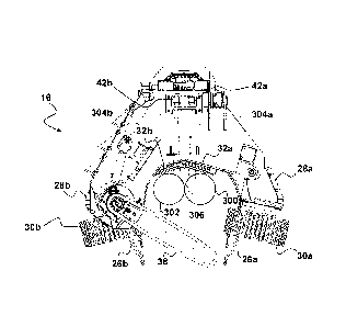
Referring to FIG. 2, the head 16 includes a frame 24 to which the tilt bracket
22 of FIG. us
pivotally attached. Right hand (RH) and left hand (LH) delimb arms 26a and 26b
are pivotally
attached to the frame 24, as are opposing RH and LH feed arms 28a and 28b. RH
and LH
feed wheels 30a and 30b are attached to RH and LH feed arms 28a and 28b
respectively,
which together with RH and LH frame-mounted feed wheels 32a and 32b may be
controlled to
feed one or more stems (not illustrated) along feed axis 34 of the head 16.
Feed wheels 30a,
30b, 32a and 32b may collectively be referred to as the 'feed mechanism.' A
measuring wheel
36 may be used to measure the length of the stem as it passes.
A main chainsaw 38, and a topping chainsaw 40, are attached to the frame 24.
The main saw
38 is typically used to fell a tree when the head 16 is in a harvesting
position, and to buck
stems into logs in the processing position of the head 16 (as seen in FIG. 1).
The topping saw
40 may be used to cut off a small-diameter top portion of the stem(s) to
maximize the value
recovery of the trees.
RH and LH optical sensors 42a and 42b are attached to the frame 24 on either
side of the feed
axis 34. The operation of the sensors 42a and 42b will be discussed further
below.
7
CA 02904241 2015-09-04
WO 2015/084183 PCT/NZ2014/000239
The various operations of the head 16 may be controlled by the operator using
hand and foot
controls as known in the art. Further, certain automated functions of the
harvester head 16
may be controlled by an electronic control system 100 as shown by FIG. 3.
The control system 100 includes one or more electronic controllers, each
controller including a
processor and memory having stored therein instructions which, when executed
by the
processor, causes the processor to perform the various operations of the
controller.
For example, the control system 100 includes a first controller 102 on board
the carrier 10 and
a second controller 104 on board the head 16. The controllers 102, 104 are
connected to one
another via a communications bus 110 (e.g., a CAN bus).
io A human operator operates an operator input device 108, for example hand
and foot controls,
located at the operator's cab 12 of the carrier 10 to control the head 16.
Details of operation
are output to an output device 110 ¨ for example a monitor. Certain automated
functions may
be controlled by first controller 102 and/or second controller 104.
The RH and LH optical sensors 42a and 42b are electronically coupled to the
second controller
104, and configured to output respective signals indicative of the end of a
stem being present
within the respective sensing regions associated with the sensors 42a and 42b.
A measuring wheel encoder 112 is electrically coupled to the second controller
104, and
configured to output a measuring signal indicating the length of the stem(s)
that has passed the
measuring wheel 36.
The head 16 has a number of valves 114 arranged, for example, in a valve block
and coupled
electrically to the second controller 104 so as to be under its control. The
valves 114 include,
for example, drive valves configured to control operation of the motors
associated with the RH
and LH feed wheels 30a and 30b and RH and LH frame-mounted feed wheels 32a and
32b.
The valves 114 further include drive valves for controlling operation of the
saws 38 and 40.
The control system 100 is configured to implement method 200 of FIG. 5, which
will be
described with reference to FIGS. 1 through 3, together with FIG. 4 showing
the head 16 in
use.
In step 202, a human operator operates the operator input device 108 to grasp
a first stem 300
and a second stem 302 with the delimb arms 26a and 26b, and feed arms 28a and
28b such
that the stems are positioned between the arm-mounted feed wheels 30a and 30b,
and frame-
mounted feed wheels 32a and 32b. The first stem 300 is positioned to the RH
side of the feed
axis 34 (see FIG. 2, not illustrated in FIG. 4), while the second stem 302 is
positioned to the LH
side of the feed axis 34.
In step 204, the first controller 102 receives from operator input device 108
a signal indicative of
8
CA 02904241 2015-09-04
WO 2015/084183 PCT/NZ2014/000239
a request to find the ends of the stems 300 and 302. In response to that
signal, the first
controller 102 broadcasts a request to find the ends of the stems 300 and 302
on bus 106.
In step 206, the second controller 104 receives the request to find the ends
of the stems 300
and 302, and outputs control signals to the valves 114 responsible for control
of the arm-
.. mounted feed wheels 30a and 30b, and frame-mounted feed wheels 32a and 32b
to feed the
stems 300 and 302 along the feed axis 34.
In step 208, as the stems 300 and 302 are fed along feed axis 34 the RH and LH
optical
sensors 42a and 42b output signals indicative of the presence of ends of the
first stem 300 and
second stem 302 being within a RH sensing region 304a and LH sensing region
304b
respectively. It may be seen that the RH and LH sensing regions 304a and 304b
do not
intersect each other, nor the path of the stem on the other side of the feed
axis 34. This
prevents a false finding of an end being located due to triggering by the end
of the other stem.
In step 208 the second controller 104 determines whether the ends of the first
stem 300 and/or
second stem 302 has been located, and outputs a control signal to valves 114
to control
.. operation of the feed mechanism.
Control of the feed mechanism will depend on the conditions detected. For
example, where
only the end of stem 300 has been located, feed arm-mounted feed wheel 30a and
frame-
mounted feed wheel 32a may be stopped, while arm-mounted feed wheel 30b and
frame-
mounted feed wheel 32b continue to feed stem 302 through until its end is
located.
Once both ends have been located, processing of the stems 300 and 302 may be
performed
as known in the art. For example, the stems 300 and 302 may be driven forward
by a
predetermined distance from their respective ends, and the saw operated to
sever the stems
and produce two logs at the desired length.
Referring to FIG. 4, it may be seen that where a single stem 306 (shown in
dashed line) is to be
processed by the head 16, either (or both) of the sensing regions 304a or 304b
of sensors 42a
and 42b respectively may be used to detect the presence of the end of the stem
306.
It is envisaged that the operator may input a selection of a single stem or
double stem mode of
operation into the control system 100 based on their observation of the number
of stems being
picked up by the head. The appropriate control routine may then be selected by
the first
controller 102 for implementation.
Aspects of the present invention have been described by way of example only
and it should be
appreciated that modifications and additions may be made thereto without
departing from the
scope thereof as defined in the appended claims.
9