Note : Les descriptions sont présentées dans la langue officielle dans laquelle elles ont été soumises.
CA 02904521 2015-09-08
WO 2014/142588 PCT/KR2014/002134
1
Description
Title of Invention: TRANSMISSION OF ACKNOWLEDGE-
MENTINFOR1VIATION IN ADAPTIVELY CONFIGURED TDD
COMMUNICATION SYSTEMS
Technical Field
[1] The present application relates generally to wireless communications
and, more
specifically, to transmitting acknowledgement information in adaptively
configured
time division duplex (TDD) communication systems.
Background Art
[2] The present application claims priority to U.S. Provisional Patent
Application Serial
No. 61/780,227 filed March 13. 2013, entitled "Transmissions of
Acknowledgement
Signals in Adaptively Configured TDD Communication Systems," U.S. Provisional
Patent Application Serial No. 61/824,855, filed May 18, 2013, entitled
"Transmission
of Uplink Control Information in Adaptively Configured TDD Communication
Systems," U.S. Provisional Patent Application Serial No. 61/877,121, filed
September
12, 2013, entitled "Transmission and Coding of Uplink Control Information in
Adaptive TDD Communication Systems." and U.S. Provisional Patent Application
61/898.269. filed October 31, 2013, entitled "Transmission and Coding of
Uplink
Control Information in Adaptive TDD Communication Systems." The above-
identified
provisional patent applications are hereby incorporated by reference in their
entirety.
[31 Wireless communication has been one of the most successful innovations
in modern
history. Recently, the number of subscribers to wireless communication
services
exceeded five billion and continues to grow quickly. The demand of wireless
data
traffic is rapidly increasing due to the growing popularity among consumers
and
businesses of smart phones and other mobile data devices, such as tablets,
"note pad"
computers, net books, and eBook readers.
Disclosure of Invention
Technical Problem
[4] In order to meet the high growth in mobile data traffic, improvements
in radio
interface efficiency and allocation of new spectrum is of paramount
importance.
Solution to Problem
[51 This disclosure provides a method and apparatus for
transmittingacknowledgement
information signaling in adaptively configured time division duplex (TDD)
commu-
nication systems.
[6] In a first embodiment, a method is provided. The method includes
transmitting, by a
CA 02904521 2015-09-08
WO 2014/142588 PCT/KR2014/002134
2
base station to a User Equipment (UE), configuration information for a first
Time
Division Duplex (TDD) UpLink-DownLink (UL-DL) configuration, a second TDD
UL-DL configuration, and a third TDD UL-DL configuration. The method also
includes transmitting, by the base station to the UEin a DL or special
SubFrame (SF)
of the third TDD UL-DL configuration, either a Physical DL Control CHannel
(PDCCH) or an Enhanced PDCCH (EPDCCH) conveying a DL Control Information
(DCI) format that schedules to the UE either a reception of a Physical DL
Shared
CHannel (PDSCH) or a release of a Semi-Persistently Scheduled (SPS) PDSCH in
the
DL or special SF. If the DCI format is conveyed by the EPDCCH it includes an
Ac-
knowledgement Resource Offset (ARO) field.In response to receiving, by the UE,
the
first TDD UL-DL configuration, the second TDD UL-DL configuration, and the
third
TDD UL-DL configuration, the UE determines, according to the second TDD UL-DL
configuration, an UL SF to transmit acknowledgement information in response to
at
least one reception of PDSCH or SPS PDSCH release in a set of DL or special
SFs of
the third TDD UL-DL configuration. The UE also receives a number of PDSCHs and
SPS PDSCH release in a subset of the set of DL or special SFs. The UE also de-
termines acknowledgement information for the set of DL and special SFs in
response
to at least the reception of the number of PDSCHs and SPS PDSCH release in the
subset of the set of DL or special SFs. The UE further determines a first
subset of the
set of DL or special SFs that are DL or special SFs in the first TDD UL-DL con-
figuration for which acknowledgement information is transmitted in the UL SF
and a
second subset of the set of DL or special SFs comprising of DL or special SFs
that are
not in the first subset. The UE also determines a first set of resources and a
second set
of resources in the UL SF. A resource in the first set of resources
corresponds to a SF
in the subset that is in the first subset. The resource is determined either
using afirst
offset if the reception is scheduled by a PDCCH or using the ARO field and
asecond
offset if the reception is scheduled by an EPDCCH. A resource in the second
set of
resources corresponds to a SF in the subset that is in the second subset. The
resource is
determined using athird offset if the reception is scheduled by a PDCCH or
using the
ARO field and the second offset if the reception is scheduled by an EPDCCH.
The UE
also selects, from the first set of resources or from the second set of
resources, a
resource of a physical UL control channel to transmit the acknowledgement in-
formation based on the values of the acknowledgement information. The UE
further
transmits, to the base station, the acknowledgement information in the
selected
resource.
171 In a second embodiment, a method is provided. The method includes
transmitting, by
a base station to a User Equipment (UE),configuration information for a first
Time
Division Duplex (TDD) UpLink-DownLink (UL-DL) configuration and a second TDD
CA 02904521 2015-09-08
WO 2014/142588 PCT/KR2014/002134
3
UL-DL configuration. Each UL SubFrame (SF) in the second TDD UL-DL con-
figuration is also an UL SF in the first TDD UL-DL configuration. The method
also
includes transmitting, by the base station to the UEin a DL SF of the first
TDD UL-DL
configuration, a control channel conveying a DL Control Information (DCI)
format
that schedules a transmission by the UE of a Physical UL Shared CHannel
(PUSCH) in
an UL SF of the first TDD UL-DL configuration and includes at least a field of
binary
elements.The UE can transmit acknowledgement information in the PUSCH if the
UL
SF is also an UL SF in the second TDD UL-DL configuration. If the UE can
transmit
acknowledgment information in the UL SF, the field functions as a DL
Assignment
Index (DAI) informing the UE of a number of DL or special SFs for the UE to
transmit
acknowledgement information. If the UE cannot transmit acknowledgment
information
in the UL SF and the UE operates with a TDD UL-DL configuration that does not
have
more UL SFs than DL and special SFs, the field value is always set to zero.
l8l In a third embodiment, a method is provided. The method includes
transmitting, by a
base station to a User Equipment (UE), configuration information for a first
Time
Division Duplex (TDD) UpLink-DownLink (UL-DL) configuration, a second TDD
UL-DL configuration, and a third TDD UL-DL configuration. The method also
includes transmitting, by the base station to the UEin a DL or special
SubFrame (SF)
of the third TDD UL-DL configuration, a Physical DL Control CHannel (PDCCH).
The PDCCH is of a first type or of a second type and conveys a DL Control In-
formation (DCI) format that schedules to the UE in the DL or special SF either
a
reception of a Physical DL Shared CHannel (PDSCH) or a release of a Semi-
Persistently Scheduled (SPS) PDSCH. In response to receiving, by the UE, the
first
TDD UL-DL configuration, the second TDD UL-DL configuration, and the third TDD
UL-DL configuration, the UEdetermines,according to the second TDD UL-DL con-
figuration, an UL SF to transmit acknowledgement information in response to at
least
one reception of PDSCH or SPS PDSCH release in a set of DL or special SFs of
the
third TDD UL-DL configuration. The UE receives a number of PDSCHs and SPS
PDSCH release in a subset of the set of DL or special SFs. The UE also
determines ac-
knowledgement information for the set of DL and special SFs in response at
least to
the reception of the number of PDSCHs and SPS PDSCH release in the subset of
the
set of DL or special SFs. The UE furtherdetermines a first subset of the set
of DL or
special SFs that are DL or special SFs in the first TDD UL-DL configuration
for which
acknowledgement information is transmitted in the UL SF and a second subset of
the
set of DL or special SFs comprising of DL or special SFs that are not in the
first
subset. The UE transmits, to the base station, the acknowledgement
information. Ac-
knowledgement information corresponding to the first set of DL or special SFs
and the
second set of DL SFs is transmitted in the UL SF. Each SF in the subset of the
one or
CA 02904521 2015-09-08
WO 2014/142588 PCT/KR2014/002134
4
more DL or special SFs is either in the first set or in the second set. The UE
further
transmits to the base station, the acknowledgement information.
Acknowledgement in-
formation corresponding to DL or special SFs in the first subset is ordered
prior to ac-
knowledgement information corresponding to DL SFs in the second subset if the
transmission is in a Physical UL Control CHannel (PUCCH) and wherein acknowl-
edgement information is ordered according to the index of a DL or special SF
in the
second TDD UL-DL configuration if the transmission is in a Physical UL Shared
CHannel (PUSCH).
I91 In a fourth embodiment, a base station is provided. The base station
includes a
transmitter configured to transmit, to a User Equipment (UE),signaling
indicating a
first Time Division Duplex (TDD) UpLink-DownLink (UL-DL) configuration,
signaling indicating a second TDD UL-DL configuration, and signaling
indicating a
third TDD UL-DL configuration. The base station also includes a transmitter
configured to transmit, to the UE,either a Physical DL Control CHannel (PDCCH)
or
an Enhanced PDCCH (EPDCCH), in a DL or special SubFrames (SFs) of the third
TDD UL-DL configuration, conveying a DL Control Information (DCI) format that
schedules to the UE either a reception of a Physical DL Shared CHannel(PDSCH)
or a
release of a Semi-Persistently Scheduled (SPS) PDSCH in the DL or special SF.
If the
DCI format is conveyed by the EPDCCH it includes an Acknowledgement Resource
Offset (ARO) field. The base station includes a receiver configured to
receive, from
the UE, acknowledgement information in a resource of a physical UL control
channel
from a first set of resources or from a second set of resources. The base
station
includes a processor configured to determinean UL SF, according to the second
TDD
UL-DL configuration, for receiving acknowledgement information for a set of DL
or
special SFs in the third TDD UL-DL configuration. The acknowledgement
information
is in response to at least one transmission of PDSCH or SPS PDSCH release in
the set
of DL or special SFs. The base station also includes a processor configured to
de-
terminea first subset of the set of DL or special SFs that are DL or special
SFs in the
first TDD UL-DL configuration for which acknowledgement information is
transmitted in the UL SF and a second subset of the set of DL or special SFs
comprising of DL or special SFs that are not in the first subset. The base
station further
includes a processor configured to determinethe first set of resources and the
second
set of resources in the UL SF. A resource in thefirst set of resources
corresponds to a
SF in the first set and is determined either using the first offset if the
transmission is
scheduled by a PDCCH or using the ARO field and asecond offset if the
transmission
is scheduled by an EPDCCH. A resource in the second set of resources
corresponds to
a SF that is in the second set and is determined using athird offset if the
transmission is
scheduled by a PDCCH or using the ARO field and the second offset if the
CA 02904521 2015-09-08
WO 2014/142588 PCT/KR2014/002134
transmission is scheduled by an EPDCCH.
[10] In a fifth embodiment, a User Equipment (UE) is provided. The UE
includes a
receiver configured to receive, from a base station,signaling indicating a
first Time
Division Duplex (TDD) UpLink-DownLink (UL-DL) configuration, signaling in-
dicating a second TDD UL-DL configuration, and signaling indicating a third
TDD
UL-DL configuration. The UE also includes a receiver configured to receive,
from the
base station,either a Physical DL Control CHannel (PDCCH) or an Enhanced PDCCH
(EPDCCH), in a DL or special SubFrames (SFs) of the third TDD UL-DL con-
figuration, conveying a DL Control Information (DCI) format that schedules to
the UE
either a reception of a Physical DL Shared CHannel (PDSCH) or a release of a
Semi-
Persistently Scheduled (SPS) PDSCH in the DL or special SF. If the DCI format
is
conveyed by the EPDCCH it includes an Acknowledgement Resource Offset (ARO)
field. The UE includes a transmitter configured to transmit, to the base
station. ac-
knowledgement information in a resource of a physical UL control channel from
a first
set of resources or from a second set of resources. The UE includes a
processor
configured to determinean UL SF, according to the second TDD UL-DL
configuration,
for the transmitting the acknowledgement information for a set of DL or
special SFs in
the third TDD UL-DL configuration.The acknowledgement information is in
response
to at least one reception of PDSCH or SPS PDSCH release in the set of DL or
special
SFs. The UE also includes a processor configured to determinea first subset of
the set
of DL or special SFs that are DL or special SFs in the first TDD UL-DL
configuration
for which acknowledgement information is transmitted in the UL SF and a second
subset of the set of DL or special SFs comprising of DL or special SFs that
are not in
the first subset. The UE further includes a processor configured to
determinethe first
set of resources and the second set of resources in the UL SF. A resource in
the first set
of resources corresponds to a SF in the first set and is determined either
using afirst
offset if the reception is scheduled by a PDCCH or using the ARO field and
asecond
offset if the reception is scheduled by an EPDCCH. A resource in the second
set of
resources conesponds to a SF that is in the second set and is determined using
athird
offset if the reception is scheduled by a PDCCH or using the ARO field and the
second
offset if the reception is scheduled by an EPDCCH.
[11] In a sixth embodiment, a base station is provided. The base station
includes a
transmitter configured to transmit, to a User Equipment (UE),signaling
indicating a
first Time Division Duplex (TDD) UpLink-DownLink (UL-DL) configurationand
signaling indicating a second TDD UL-DL configuration. Each UL SubFrame (SF)
in
the second TDD UL-DL configuration is also an UL SF in the first TDD UL-DL con-
figuration. The base station also includes a transmitter configured to
transmit, to the
UE in a DL SF of the first TDD UL-DL configuration,a control channelconveying
a
CA 02904521 2015-09-08
WO 2014/142588 PCT/KR2014/002134
6
DL Control Information (DCI) format that schedules a transmission, by the UE,
of a
Physical UL Shared CHannel (PUSCH) in an UL SF of the first TDD UL-DL con-
figuration and includes at least a field of binary elements. The UE can
include ac-
knowledgement information in the PUSCH if the UL SF is also an UL SF in the
second TDD UL-DL configuration. If the UE can transmit acknowledgment in-
formation in the UL SF, the field functions as a DL Assignment Index (DAI)
informing the UE of a number of DL or special SFs for the UE to transmit
acknowl-
edgement information. If the UE cannot transmit acknowledgment information in
the
UL SF and the UE operates with a TDD UL-DL configuration that does not have
more
UL SFs than DL and special SFs, the field value is always set to zero.
[12] Before undertaking the DETAILED DESCRIPTION below, it may be
advantageous
to set forth definitions of certain words and phrases used throughout this
patent
document. The term "couple" and its derivatives refer to any direct or
indirect commu-
nication between two or more elements, whether or not those elements are in
physical
contact with one another. The terms "transmit," "receive," and "communicate,"
as well
as derivatives thereof, encompass both direct and indirect communication. The
terms
"include" and "comprise," as well as derivatives thereof, mean inclusion
without
limitation. The term -or" is inclusive, meaning and/or. The phrase "associated
with,"
as well as derivatives thereof, means to include, be included within,
interconnect with,
contain, be contained within, connect to or with, couple to or with, be
communicable
with, cooperate with, interleave, juxtapose, be proximate to, be bound to or
with, have,
have a property of, have a relationship to or with, or the like. The term
"controller"
means any device, system or part thereof that controls at least one operation.
Such a
controller may be implemented in hardware or a combination of hardware and
software
and/or firmware. The functionality associated with any particular controller
may be
centralized or distributed, whether locally or remotely. The phrase "at least
one of,"
when used with a list of items, means that different combinations of one or
more of the
listed items may be used, and only one item in the list may be needed. For
example, "at
least one of: A, B, and C" includes any of the following combinations: A, B,
C, A and
B. A and C, B and C, and A and B and C.
[13] Moreover, various functions described below can be implemented or
supported by
one or more computer programs, each of which is formed from computer readable
program code and embodied in a computer readable medium. The terms
"application"
and "program" refer to one or more computer programs, software components,
sets of
instructions, procedures, functions, objects, classes, instances, related
data, or a portion
thereof adapted for implementation in a suitable computer readable program
code. The
phrase "computer readable program code" includes any type of computer code,
including source code, object code, and executable code. The phrase "computer
7
readable medium" includes any type of medium capable of being accessed by a
computer, such as read only memory (ROM), random access memory (RAM), a hard
disk drive, a compact disc (CD), a digital video disc (DVD), or any other type
of
memory. A "non-transitory" computer readable medium excludes wired, wireless,
optical, or other communication links that transport transitory electrical or
other
signals. A non-transitory computer readable medium includes media where data
can
be permanently stored and media where data can be stored and later
overwritten, such
as a rewritable optical disc or an erasable memory device.
According to an aspect of the present invention, there is provided a method
for receiving acknowledgement information in a wireless communication system
using time division duplex (TDD), the method comprising:
identifying a first uplink-downlink (UL-DL) configuration, a second UL-DL
configuration, and a third UL-DL configuration, wherein the first UL-DL
configuration is a semi-statically configured UL-DL configuration, the second
UL-
DL configuration is a reference UL-DL configuration for acknowledgement
transmission timing, and the third UL-DL configuration is a dynamically
adapted
UL-DL configuration;
transmitting, by a base station to a user equipment (UE), downlink control
information in a DL or special subframe (SF) of the third UL-DL configuration;
transmitting downlink data scheduled by the downlink control information in
the DL or special SF; and
receiving acknowledgement information associated with the downlink data on
a resource in an UL SF which is determined based on the second UL-DL
configuration,
wherein in case that the DL or special SF is included in DL and special SFs in
the first UL-DL configuration, the resource is determined based on a first
offset, and
wherein in case that the DL or special SF is not included in DL and special
SFs in the first UL-DL configuration, the resource is determined based on a
second
offset.
According to another aspect of the present invention, there is provided a
method for transmitting acknowledgement information in a wireless
communication
system using time division duplex (TDD), the method comprising:
Date Recue/Date Received 2020-08-06
7a
identifying a first uplink-downlink (UL-DL) configuration, a second UL-DL
configuration, and a third UL-DL configuration, wherein the first UL-DL
configuration
is a semi-statically configured UL-DL configuration, the second UL-DL
configuration
is a reference UL-DL configuration for acknowledgement transmission timing,
and the
third UL-DL configuration is a dynamically adapted UL-DL configuration;
receiving, from a base station by a user equipment (UE), downlink control
information in a DL or special subframe (SF) of the third UL-DL configuration;
receiving downlink data scheduled by the downlink control information in the
DL or special SF; and
transmitting acknowledgement information associated with the downlink data
on a resource in an UL SF which is determined based on the second UL-DL
configuration,
wherein in case that the DL or special SF is included in DL and special SFs in
the first UL-DL configuration, the resource is determined based on a first
offset, and
wherein in case that the DL or special SF is not included in DL and special
SFs
in the first UL-DL configuration, the resource is determined based on a second
offset.
According to another aspect of the present invention, there is provided a base
station for receiving acknowledgement information in a wireless communication
system using time division duplex (TDD), the base station comprising:
a RF transceiver configured to transmit and receive signals to and from a user
equipment (UE); and
a controller coupled with the RF transceiver and configured to:
identify a first uplink-downlink (UL-DL) configuration, a second UL-DL
configuration, and a third UL-DL configuration, wherein the first UL-DL
configuration
is a semi-statically configured UL-DL configuration, the second UL-DL
configuration
is a reference UL-DL configuration for acknowledgement transmission timing,
and the
third UL-DL configuration is a dynamically adapted UL-DL configuration,
transmit downlink control information in a DL or special subframe (SF) of the
third UL-DL configuration,
transmit downlink data scheduled by the downlink control information in the
DL or special SF, and
receive acknowledgement information associated with the downlink data on a
Date Recue/Date Received 2020-08-06
resource in an UL SF which is determined based on the second UL-DL
configuration,
wherein in case that the DL or special SF is included in DL and special SFs in
the first UL-DL configuration, the resource is determined based on a first
offset, and
wherein in case that the DL or special SF is not included in DL and special
SFs
in the first UL-DL configuration, the resource is determined based on a second
offset.
According to another aspect of the present invention, there is provided a user
equipment (UE) for transmitting acknowledgement information in a wireless
communication system using time division duplex (TDD), the UE comprising:
a RF transceiver configured to transmit and receive signals to and from a base
station; and
a controller coupled with the RF transceiver and configured to:
identify a first uplink-downlink (UL-DL) configuration, a second UL-DL
configuration, and a third UL-DL configuration, wherein the first UL-DL
configuration
is a semi-statically configured UL-DL configuration, the second UL-DL
configuration
is a reference UL-DL configuration for acknowledgement transmission timing,
and the
third UL-DL configuration is a dynamically adapted UL-DL configuration,
receive downlink control information in a DL or special subframe (SF) of the
third UL-DL configuration,
receive downlink data scheduled by the downlink control information in the DL
or special SF, and
transmit acknowledgement information associated with the downlink data on a
resource in an UL SF which is determined based on the second UL-DL
configuration,
and
wherein in case that the DL or special SF is included in DL and special SFs in
the first UL-DL configuration, the resource is determined based on a first
offset, and
wherein in case that the DL or special SF is not included in DL and special
SFs
in the first UL-DL configuration, the resource is determined based on a second
offset.
[14] Definitions for other certain words and phrases are provided throughout
this
patent document. Those of ordinary skill in the art should understand that in
many if
not most instances, such definitions apply to prior as well as future uses of
such
defined words and phrases.
Date Recue/Date Received 2020-08-06
7c
Brief Description of Drawings
[15] For a more complete understanding of the present disclosure and its
advantages, reference is now made to the following description taken in
conjunction
with the accompanying drawings, in which like reference numerals represent
like
parts:
[16] FIGURE 1 illustrates an example wireless communication network according
to this disclosure;
[17] FIGURE 2 illustrates an example user equipment (UE) according to this
disclosure;
[18] FIGURE 3 illustrates an example eNodeB (eNB) according to this
disclosure;
[19] FIGURE 4 illustrates an example PUSCH transmission structure over a
Transmission Time Interval (TTI) according to this disclosure;
[20] FIGURE 5 illustrates an example UE transmitter structure for data
information and UCI in a PUSCH according to this disclosure;
[21] FIGURE 6 illustrates an example eNB receiver structure for data
information
and UCI in a PUSCH according to this disclosure;
[22] FIGURE 7 illustrates an example PUCCH Format 3 structure in one TTI slot
for HARQ-ACK transmission with joint coding according to this disclosure;
[23] FIGURE 8 illustrates an example UE transmitter block diagram for HARQ-
ACK information using a PUCCH Format 3 according to this disclosure;
[24] FIGURE 9 illustrates an example NB receiver block diagram for HARQ-
ACK information using a PUCCH Format 3 according to this disclosure;
[25] FIGURE 10 illustrates an example PUCCH Format la/lb structure in one slot
of a TTI according to this disclosure;
[26] FIGURE 11 illustrates an example transmitter structure for a PUCCH Format
la/lb according to this disclosure;
[27] FIGURE 12 illustrates an example receiver structure for a PUCCH Format
Date Recue/Date Received 2020-08-06
CA 02904521 2015-09-08
WO 2014/142588 PCT/KR2014/002134
8
la/lbaccording to this disclosure;
[28] FIGURE 13 illustratesan example of different interference
characteristics in different
flexible TTIs according to this disclosure;
[29] FIGURE 14 illustrates example HARQ-ACK transmissions in a same UL TTI
for 2
different TDD UL-DL configurationsaccording to this disclosure;
[30] FIGURE 15 illustrates an example indexing of DL TTIs in an adapted TDD
UL-DL
configuration, relative to a conventional TDD UL-DL configuration, for
determining
PUCCH resources for respective HARQ-ACK signal transmissionsaccording to this
disclosure;
[31] FIGURE 16 illustrates an example determination of a PUCCH resource for
HARQ-
ACK signal transmission using a PUCCH resource offset depending on a DL TTI
index of a respective PDSCH reception in an adapted TDD UL-DL configuration
according to this disclosure;
[32] FIGURE 17 illustrates an example implicit or explicit determination of
a PUCCH
resource for HARQ-ACK signaling depending on whether or not a respective DL
TTI
index is included in a conventional TDD UL-DL configuration, respectively,
according
to this disclosure;
[33] FIGURE 18 illustrates an example determination by a UE whether to
multiplex UCI
in a PUSCH depending on an associated UL PC process according to this
disclosure;
[34] FIGURE 19 illustrates an exampledetermination by a UE whether to
multiplex UCI
in a PUSCH depending on a respective TTI according to this disclosure;
[35] FIGURE 20 illustrates an example use of an UL DAI field included in a
DCI format
scheduling a PUSCH transmission in a TTI depending on whether or not a UE mul-
tiplexes HARQ-ACK in the PUSCH in the TTI according to this disclosure;
[36] FIGURE 21 illustrates an effective bundling window size if HARQ-ACK is
only
multiplexed in a PUSCH of predetermined UL TTIs according to this disclosure;
[37] FIGURE 22 illustrates an exampleUE decision for multiplexing UCI in a
PUSCH
transmitted in a TTI according to a UCI type and the TTI type according to
this
disclosure;
[38] FIGURE 23 illustrates an example multiplexing in a same PUCCH of a
first CQI cor-
responding to a first set of TT1s, of second CQI corresponding to a second set
of TTIs,
and of a single PMI corresponding to both sets of TTIsaccording to this
disclosure;
[39] FIGURE 24 illustrates an exampleUE transmitter block diagram for HARQ-
ACK, P-
CSI for a first set of TTIs, and P-CSI for a second set of TTIsaccording to
this
disclosure;
1401 FIGURE 25 illustrates an exampleeNB receiver block diagram for HARQ-
ACK, P-
CSI for a first set of TTIs, and P-CSI for a second set of TTIs according to
this
disclosure;
CA 02904521 2015-09-08
WO 2014/142588 PCT/KR2014/002134
9
[41] FIGURE 26 illustrates an example resource allocation for PUCCH Format
3
depending on a maximum total payload according to this disclosure;
1421 FIGURE 27 illustrates an example PUCCH Format 3 transmission over 2
RBs
according to this disclosure;
[43] FIGURE 28 illustrates an exampleDL or UL scheduling and HARQ-ACK
transmission for a UE operating with an adapted TDD UL-DL configuration
followed
by operation with a conventional TDD UL-DL configuration according to this
disclosure;
[44] FIGURE 29 illustrates an example transmission of HARQ-ACK information
from a
UE in response to detection or absence of detection by the UE of a PDCCH
intended to
a group of UEs where the HARQ-ACK information is included with other HARQ-
ACK information transmitted from the UE in response to PDCCH detections as-
sociated with UE-specific DL scheduling according to this disclosure; and
[45] FIGURE 30 illustrates an example interpretation of a field in a DCI
format
scheduling a PUSCH either as an UL index or as an UL DAI by a UE configured to
operate with an adapted TDD UL-DL configuration and with TDD UL-DL con-
figuration 0 as theconventionalTDD UL-DL configurationaccording to this
disclosure.
Mode for the Invention
[46] The present application claims priority to U.S. Provisional Patent
Application Serial
No. 61/780,227 filed March 13, 2013, entitled "Transmissions of
Acknowledgement
Signals in Adaptively Configured TDD Communication Systems," U.S. Provisional
Patent Application Serial No. 61/824,855, filed May 18, 2013, entitled
"Transmission
of Uplink Control Information in Adaptively Configured TDD Communication
Systems," U.S. Provisional Patent Application Serial No. 61/877,121, filed
September
12, 2013, entitled "Transmission and Coding of Uplink Control Information in
Adaptive TDD Communication Systems," and U.S. Provisional Patent Application
61/898,269, filed October 31, 2013, entitled "Transmission and Coding of
Uplink
Control Information in Adaptive TDD Communication Systems." The above-
identified
provisional patent applications are hereby incorporated by reference in their
entirety.
[47] FIGURES 1 through 30, discussed below, and the various embodiments
used to
describe the principles of the present disclosure in this patent document are
by way of
illustration only and should not he construed in any way to limit the scope of
the
disclosure.Those skilled in the art will understand that the principles of the
present
disclosure may be implemented in any suitably arranged wireless communication
system.
[48] The following documents and standards descriptions are hereby
incorporated into the
present disclosure as if fully set forth herein: 3GPP TS 36.211 v11.1.0, "E-
UTRA,
CA 02904521 2015-09-08
WO 2014/142588 PCT/KR2014/002134
Physical channels and modulation" (REF 1); 3GPP TS 36.212 v11.1.0, "E-UTRA,
Multiplexing and Channel coding" (REF 2): 3GPP TS 36.213 v11.1.0, "E-UTRA,
Physical Layer Procedures" (REF 3); and 3GPP TS 36.331 v11.1.0, "E-UTRA, Radio
Resource Control (RRC) Protocol Specification." (REF 4).
[49] This disclosure relates to the adaptation of communication direction
in wireless com-
munication networks that utilize Time Division Duplex (TDD). A wireless commu-
nication network includes a DownLink (DL) that conveys signals from
transmission
points (such as base stations or eNodeBs) to user equipments (UEs). The
wireless com-
munication network also includes an UpLink (UL) that conveys signals from UEs
to
reception points such as eNodeBs.
[50] FIGURE 1 illustrates an example wireless network 100 according to this
disclosure.
The embodiment of the wireless network 100 shown in FIGURE 1 is for
illustration
only. Other embodiments of the wireless network 100 could be used without
departing
from the scope of this disclosure.
[51] As shown in FIGURE 1, the wireless network 100 includes an eNodeB
(eNB) 101,
an eNB 102, and an eNB 103. The eNB 101 communicates with the eNB 102 and the
eNB 103. The eNB 101 also communicates with at least one Internet Protocol
(IP)
network 130, such as the Internet, a proprietary IP network, or other data
network.
[52] Depending on the network type, other well-known terms may be used
instead of
"eNodeB" or "eNB," such as "base station" or "access point." For the sake of
con-
venience, the terms "eNodeB" and "eNB" are used in this patent document to
refer to
network infrastructure components that provide wireless access to remote
terminals.
Also, depending on the network type, other well-known terms may be used
instead of
"user equipment" or "UE," such as "mobile station," "subscriber station,"
"remote
terminal," "wireless terminal," or "user device." For the sake of convenience,
the terms
"user equipment" and "UE" are used in this patent document to refer to remote
wireless equipment that wirelessly accesses an eNB, whether the UE is a mobile
device
(such as a mobile telephone or smartphone) or is normally considered a
stationary
device (such as a desktop computer or vending machine).
[53] The eNB 102 provides wireless broadband access to the network 130 for
a first
plurality of user equipments (UEs) within a coverage area 120 of the eNB 102.
The
first plurality of UEs includes a UE 111, which may be located in a small
business
(SB); a UE 112, which may be located in an enterprise (E); a UE 113, which may
be
located in a WiFi hotspot (HS); a UE 114, which may be located in a first
residence
(R); a UE 115, which may be located in a second residence (R); and a UE 116,
which
may be a mobile device (M) like a cell phone, a wireless laptop, a wireless
PDA, or the
like. The eNB 103 provides wireless broadband access to the network 130 for a
second
plurality of UEs within a coverage area 125 of the eNB 103. The second
plurality of
CA 02904521 2015-09-08
WO 2014/142588 PCT/KR2014/002134
11
UEs includes the UE 115 and the UE 116. In some embodiments, one or more of
the
eNBs 101-103 may communicate with each other and with the UEs 111-116 using
5G,
LTE, LTE-A, WiMAX, or other advanced wireless communication techniques.
11541 Dotted lines show the approximate extents of the coverage areas 120
and 125, which
are shown as approximately circular for the purposes of illustration and
explanation
only. It should be clearly understood that the coverage areas associated with
eNBs,
such as the coverage areas 120 and 125, may have other shapes, including
irregular
shapes, depending upon the configuration of the eNBs and variations in the
radio en-
vironment associated with natural and man-made obstructions.
11551 As described in more detail below, various components of the network
100 (such as
the cNBs 101-103 and/or the UEs 111-116) support transmitting acknowledgement
in-
formation signaling in the network 100, which can utilize TDD.
11561 Although FIGURE 1 illustrates one example of a wireless network 100,
various
changes may be made to FIGURE 1. For example, the wireless network 100 could
include any number of eNBs and any number of UEs in any suitable arrangement.
Also, the eNB 101 could communicate directly with any number of UEs and
provide
those UEs with wireless broadband access to the network 130. Similarly, each
eNB
102-103 could communicate directly with the network 130 and provide UEs with
direct wireless broadband access to the network 130. Further, the eNB 101,
102, and/or
103 could provide access to other or additional external networks, such as
external
telephone networks or other types of data networks.
11571 FIGURE 2 illustrates an example UE 114 according to this disclosure.
The em-
bodiment of the UE 114 shown in FIGURE 2 is for illustration only, and the
other UEs
in FIGURE 1 could have the same or similar configuration. However, UEs come in
a
wide variety of configurations, and FIGURE 2 does not limit the scope of this
disclosure to any particular implementation of a UE.
11581 As shown in FIGURE 2, the UE 114 includes an antenna 205, a radio
frequency (RF)
transceiver 210. transmit (TX) processing circuitry 215, a microphone 220, and
receive
(RX) processing circuitry 225. The UE 114 also includes a speaker 230, a main
processor 240, an input/output (I/O) interface (IF) 245, a keypad 250, a
display 255,
and a memory 260. The memory 260 includes a basic operating system (OS)
program
261 and one or more applications 262.
11591 The RF transceiver 210 receives, from the antenna 205, an incoming RF
signal
transmitted by an eNB or another UE. The RF transceiver 210 down-converts the
incoming RF signal to generate an intermediate frequency (IF) or baseband
signal. The
IF or baseband signal is sent to the RX processing circuitry 225, which
generates a
processed baseband signal by filtering, decoding, and/or digitizing the
baseband or IF
signal. The RX processing circuitry 225 transmits the processed baseband
signal to the
CA 02904521 2015-09-08
WO 2014/142588 PCT/KR2014/002134
12
speaker 230 (such as for voice data) or to the main processor 240 for further
processing
(such as for web browsing data).
[60] The TX processing circuitry 215 receives analog or digital voice data
from the mi-
crophone 220 or other outgoing baseband data (such as web data, e-mail, or
interactive
video game data) from the main processor 240. The TX processing circuitry 215
encodes, multiplexes, and/or digitizes the outgoing baseband data to generate
a
processed baseband or IF signal. The RF transceiver 210 receives the outgoing
processed baseband or IF signal from the TX processing circuitry 215 and up-
converts
the baseband or IF signal to an RF signalthat is transmitted via the antenna
205.
[61] The main processor 240 can include one or more processors or other
processing
devices and can execute the basic OS program 261 stored in the memory 260 in
order
to control the overall operation of the UE 114. For example, the main
processor 240
could control the reception of forward channel signals and the transmission of
reverse
channel signals by the RF transceiver 210, the RX processing circuitry 225,
and the TX
processing circuitry 215 in accordance with well-known principles. In some em-
bodiments, the main processor 240 includes at least one microprocessor or
micro-
controller.
[62] The main processor 240 is also capable of executing other processes
and programs
resident in the memory 260. The main processor 240 can move data into or out
of the
memory 260 as required by an executing processsuch as operations in support of
transmitting acknowledgement signals in adaptively configured time division
duplex
(TDD) communication systems. In some embodiments, the main processor 240 is
configured to execute the applications 262 based on the OS program 261 or in
response
to signals received from eNBs, other UEs, or an operator. The main processor
240 is
also coupled to the I/0 interface 245, which provides the UE 114 with the
ability to
connect to other devices such as laptop computers and handheld computers. The
I/O
interface 245 is the communication path between these accessories and the main
processor 240.
[63] The main processor 240 is also coupled to the keypad 250 and the
display unit 255.
The operator of the UE 114 can use the keypad 250 to enter data into the UE
114. The
display 255 may be a liquid crystal display or other display capable of
rendering text
and/or at least limited graphics, such as from web sites. The display 255
could also
represent a touchscreen.
[64] The memory 260 is coupled to the main processor 240. Part of the
memory 260 could
include a random access memory (RAM), and another part of the memory 260 could
include a Flash memory or other read-only memory (ROM).
[65] As described in more detail below, the transmit and receive paths of
the UE 114
(implemented using the RF transceiver 210, TX processing circuitry 215, and/or
RX
CA 02904521 2015-09-08
WO 2014/142588 PCT/KR2014/002134
13
processing circuitry 225) support downlink signaling for uplink and downlink
adaptation in adaptively configured TDD systems.
[66] Although FIGURE 2 illustrates one example of UE 114, various changes
may be
made to FIGURE 2. For example, various components in FIGURE 2 could be
combined, further subdivided, or omitted and additional components could be
added
according to particular needs. As a particular example, the main processor 240
could
be divided into multiple processors, such as one or more central processing
units
(CPUs) and one or more graphics processing units (GPUs). Also, while FIGURE 2
il-
lustrates the UE 114 configured as a mobile telephone or smartphone, UEs could
be
configured to operate as other types of mobile or stationary devices. In
addition,
various components in FIGURE 2 could be replicated, such as when different RF
components are used to communicate with the eNBs 101-103 and with other UEs.
[67] FIGURE 3 illustrates an example eNB 102 according to this disclosure.
The em-
bodiment of the eNB 102 shown in FIGURE 3 is for illustration only, and other
eNBs
of FIGURE 1 could have the same or similar configuration. However, eNBs come
in a
wide variety of configurations, and FIGURE 3 does not limit the scope of this
disclosure to any particular implementation of an eNB.
[68] As shown in FIGURE 3, the eNB 102 includes multiple antennas 305a-
305n,
multiple RF transceivers 310a-310n. transmit (TX) processing circuitry 315,
and
receive (RX) processing circuitry 320. The eNB 102 also includes a controller/
processor 325, a memory 330, and a backhaul or network interface 335.
[69] The RF transceivers 310a-310n receive. from the antennas 305a-305n,
incoming RF
signals, such as signals transmitted by UEs or other eNBs. The RF transceivers
310a-310n down-convert the incoming RF signals to generate IF or baseband
signals.
The IF or baseband signals are sent to the RX processing circuitry 320, which
generates processed baseband signals by filtering, decoding, and/or digitizing
the
baseband or IF signals. The RX processing circuitry 320 transmits the
processed
baseband signals to the controller/ processor 325 for further processing.
[70] The TX processing circuitry 315 receives analog or digital data (such
as voice data,
web data, e-mail, or interactive video game data) from the
controller/processor 325.
The TX processing circuitry 315 encodes, multiplexes, and/or digitizes the
outgoing
baseband data to generate processed baseband or IF signals. The RF
transceivers
310a-310n receive the outgoing processed baseband or IF signals from the TX
processing circuitry 315 and up-converts the baseband or IF signals to RF
signals that
are transmitted via the antennas 305a-305n.
1711 The controller/processor 325 can include one or more processors or
other processing
devices that control the overall operation of the eNB 102. For example, the
controller/
processor 325 could control the reception of forward channel signals and the
CA 02904521 2015-09-08
WO 2014/142588 PCT/KR2014/002134
14
transmission of reverse channel signals by the RF transceivers 310a-310n, the
RX
processing circuitry 320, and the TX processing circuitry 315 in accordance
with well-
known principles. The controller/processor 325 could support additional
functions as
well, such as more advanced wireless communication functions. For instance,
the
controller/processor 325 could support beam forming or directional routing
operations
in which outgoing signals from multiple antennas 305a-305n are weighted
differently
to effectively steer the outgoing signals in a desired direction. Any of a
wide variety of
other functions could be supported in the eNB 102 by the controller/processor
325. In
some embodiments, the controller/ processor 325 includes at least one
microprocessor
or microcontroller.
[72] The controller/processor 325 is also capable of executing programs and
other
processes resident in the memory 330, such as a basic OS and operations in
support of
providing channel state information for scheduling downlink transmissions in
adaptively configured time division duplex (TDD) communication systems. The
controller/processor 325 can move data into or out of the memory 330 as
required by
an executing process.
[73] The controller/processor 325 is also coupled to the backhaul or
network interface
335. The backhaul or network interface 335 allows the eNB 102 to communicate
with
other devices or systems over a backhaul connection or over a network. The
interface
335 could support communications over any suitable wired or wireless
connection(s).
For example, when the eNB 102 is implemented as part of a cellular
communication
system (such as one supporting 5G, LTE, or LTE-A), the interface 335 could
allow the
eNB 102 to communicate with other eNBs over a wired or wireless backhaul
connection. When the eNB 102 is implemented as an access point, the interface
335
could allow the eNB 102 to communicate over a wired or wireless local area
network
or over a wired or wireless connection to a larger network (such as the
Internet). The
interface 335 includes any suitable structure supporting communications over a
wired
or wireless connection, such as an Ethernet or RF transceiver.
[74] The memory 330 is coupled to the controller/processor 325. Part of the
memory 330
could include a RAM, and another part of the memory 330 could include a Flash
memory or other ROM.
[75] As described in more detail below, the transmit and receive paths of
the eNB 102
(implemented using the RF transceivers310a-310n, TX processing circuitry 315,
and/
or RX processing circuitry 320) support downlink signaling for uplink and
downlink
adaptation in adaptively configured TDD systems.
1761 Although FIGURE 3 illustrates one example of an eNB 102, various
changes may be
made to FIGURE 3. For example, the eNB 102 could include any number of each
component shown in FIGURE 3. As a particular example, an access point could
CA 02904521 2015-09-08
WO 2014/142588 PCT/KR2014/002134
include a number of interfaces 335, and the controller/processor 325 could
support
routing functions to route data between different network addresses. As
another
particular example, while shown as including a single instance of TX
processing
circuitry 315 and a single instance of RX processing circuitry 320, the eNB
102 could
include multiple instances of each (such as one per RF transceiver).
[77] In some wireless networks, DL signals include data signals conveying
information
content, control signals conveying DL Control Information (DCI), and Reference
Signals (RS). An eNB transmits data information through respective Physical DL
Shared CHannels (PDSCHs). An eNB transmits DC1 over Physical DL Control
CHannels (PDCCHs) or Enhanced PDCCHs (EPDCCHs). A PDCCH is transmitted
over one or more Control Channel Elements (CCEs) while an EPDCCH is
transmitted
over ECCEs (see also REF 1). An eNB, such as eNB 102, transmits one or more of
multiple types of RS including a UE-Common RS (CRS), a Channel State
Information
RS (CSI-RS), and a DeModulation RS (DMRS). A CRS is effectively transmitted
over
an entire DLBandWidth (BW) and can be used by UEs, such as UE 114, to
demodulate
PDSCH or PDCCH, or to perform measurements. eNB 102 also can transmit CSI-RS
with a smaller density in the time and/or frequency domain than a CRS. DMRS is
transmitted only in a BW of a respective PDSCH or PDCCH and UE 114 can use a
DMRS to coherently demodulate information in a PDSCH or EPDCCH (see also REF
1).
1781 In some wireless networks, UL signals can include data signals
conveying in-
formation content, control signals conveying UL Control Information (UCI), and
RS.
UE 114 transmits data information or UCI through a respective Physical UL
Shared
CHannel (PUSCH) or a Physical UL Control CHannel (PUCCH). If UE 114 transmits
data information and UCI in a same Transmission Time Interval (TTI), UE 114can
multiplex both in a PUSCH. UCI includes Hybrid Automatic Repeat reQuestAC-
Knowledgement (HARQ-ACK) information, indicating correct (ACK) or incorrect
(NACK) detection of data Transport Blocks (TBs) in a PDSCH, Scheduling Request
(SR) indicating whether UE 114 has data in its buffer, and Channel State
Information
(CSI) enabling eNB 102 to select appropriate parameters for PDSCH or PDCCH
trans-
missions to UE 114. If UE 114 fails to detect a PDCCH scheduling a PDSCH, UE
114
can indicate this using a HARQ-ACK state referred to as DTX. A DTX and a NACK
can often be mapped on a same value (NACK/DTX value, see also REF 3). UL RS
includes DMRS and Sounding RS (SRS). DMRS is transmitted only in a BW of a re-
spective PUSCH or PUCCH. eNB 102 can use a DMRS for coherent demodulation of
information in a PUSCH or PUCCH. SRS is transmitted by UE 114 to provide eNB
102with an UL CSI.
1791 CSI transmission can be periodic (P-CSI) in a PUCCH with parameters
configured to
CA 02904521 2015-09-08
WO 2014/142588 PCT/KR2014/002134
16
UE 114 by higher layer signaling, such as for example Radio Resource Control
(RRC)
signaling, or aperiodic (A-CSI) in a PUSCH as triggered by an A-CSI request
field
included in a DCI format conveyed by a PDCCH scheduling the PUSCH (see also
REF
2). DMRS is transmitted only in a BW of a respective PUSCH or PUCCH and eNB
102 can use a DMRS to demodulate information in a PUSCH or PUCCH. SRS is
transmitted byUE 114 in order to provide eNB 102 with an UL CSI. SRS
transmission
from UE 114 can be periodic (P-SRS) at predetermined instances with
transmission pa-
rameters configured to UE 114 by higher layer signaling or it can be aperiodic
(A-SRS) as triggered by a DCI format conveyed by a PDCCH scheduling PUSCH or
PDSCH (see also REF 2).
[80] A CSI report from UE 114 includes a Channel Quality Indicator (CQI)
and the CSI
reportcan also include a Precoding Matrix Indicator (PMI). The CQI indicates
to eNB
102 a Modulation and Coding Scheme (MCS) for a PDSCH transmission to UE 114.
The PMI indicates a combining of a PDSCH transmission from multiple eNB
antenna
ports in accordance with a Multiple Input Multiple Output (MIMO) transmission
method. An RI report from UE 114 provides information to a serving eNB for a
number of spatial layers that can be supported for a PDSCH. Table 1 indicates
exemplary values for a 4-bit CQI (16 index values) transmitted in a PUCCH (see
also
REF 3). Table 2 indicates a mapping for an MCS field, Imcs in a DCI format
scheduling
a PDSCH toa modulation order (Qõ,) and a Transport Block Size (TB S) index,
ITBs, for
data transmission in the PDSCH. When UE 114experiences a high Signal-to-Noise
and
Interference Ratio (SINR), it can be configured by eNB 102 aCQ1 Table having
16
index values, similar to Table 1, and a Modulation and TBS index Table,
similar to
Table 2, but also including use of 256QAM modulation to support higher values
for
spectral efficiency.
[81] Table 1
CA 02904521 2015-09-08
WO 2014/142588
PCT/KR2014/002134
17
[Table 1]
4-bit CQI Table
CQI Modulatio code rate x 1024 efficiency
index n
0 out of range
1 QPSK 78 0.1523
2 QPSK 120 0.2344
3 QPSK 193 0.3770
4 QPSK 308 0.6016
QPSK 449 0.8770
6 QPSK 602 1.1758
7 16QAM 378 1.4766
8 16QAM 490 1.9141
9 16QAM 616 2.4063
64QAM 466 2.7305
11 64QAM 567 3.3223
12 64QAM 666 3.9023
13 64QAM 772 4.5234
14 64QAM 873 5.1152
64QAM 948 5.5547
[82]
[83] Table 2
CA 02904521 2015-09-08
WO 2014/142588 PCT/KR2014/002134
18
[Table 2]
Modulation and TBS index table for PDSCH
MCS IndexImcs Modulation OrderQ,, TBS IndexITas
0 2 0
1 2 1
2 2 2
3 2 3
4 2 4
2 5
6 2 6
7 2 7
8 2 8
9 2 9
4 9
11 4 10
12 4 11
13 4 12
14 4 13
4 14
16 4 15
17 6 15
18 6 16
19 6 17
6 18
21 6 19
22 6 20
23 6 21
[84] A DMRS or SRS transmission can be through a transmission of a
respective Zadoff-
Chu (ZC) sequence (see also REF 1). Different CSs of a ZC sequence can provide
or-
thogonal ZC sequences and can be allocated to different UEs to achieve
orthogonal
multiplexing of respective HARQ-ACK signals and RS in a same PRB. Such or-
CA 02904521 2015-09-08
WO 2014/142588
PCT/KR2014/002134
19
thogonal multiplexing can also be in the time domain using Orthogonal Covering
Codes (OCC). In this manner, as is subsequently described, a PUCCH
multiplexing
capacity per RB is increased by a factor of 3 (determined by the OCC with the
smaller
length). A PUCCH resource npuccll in a RB for HARQ-ACK signal or DMRS
transmission is defined by a pair of an OCC no, and a CS . If all
resources within a
PUCCH RB are used, resources in an immediately next RB can be used.
[85] A PUSCH or a PUCCH transmission power is determined so that an
associated
signal is received with a desired SINR at eNB 102 while controlling a
respective in-
terference to neighboring cells thereby achieving a reception reliability
target and
ensuring proper network operation. UL Power Control (PC) includes Open-Loop
Power Control (OLPC) with cell-specific and UE-specific parameters and Closed
Loop
Power Control (CLPC) corrections provided by eNB 102 through Transmission
Power
Control (TPC) commands (see also REF 3). If a PUSCH transmission is scheduled
by
a PDCCH, a TPC command is included in a respective DCI format. TPC commands
can also be provided by a separate PDCCH conveying a DCI format 3 or a DCI
format
3A, jointly referred to as DCI format 3/3A, providing TPC commands to a group
of
UEs. A DCI format includes Cyclic Redundancy Check (CRC) bits and UE 114
identifies a DCI format type from a respective Radio Network Temporary
Identifier
(RNTI) used to scramble the CRC bits. For DCI format 3/3A, a RNTI is a TPC-
RNTI
UE 114 is configured by higher layer signaling. For a DCI format scheduling a
PUSCH transmission from UE 114 or a PDSCH transmission to UE 114, a RNTI is a
Cell RNTI (C-RNTI). Additional RNTI types also exist. A power of a SRS
transmission follows a power of a PUSCH transmission power.
[86] FIGURE 4 illustrates an example PUSCH transmission structure over a
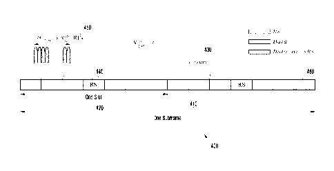
TTI
according to this disclosure. The embodiment of the PUSCH transmission
structure
400 over a TTI shown in FIGURE 4 is for illustration only. Other embodiments
could
be used without departing from the scope of the present disclosure.
[87] As shown in FIGURE 4, a TTI corresponds to one subframe 410 that
includes two
slots. Each slot 420 includes u-/- symbols 430 for transmitting data
information,
N symb
UCI. or RS. Some TTI symbols in each slot are used for transmitting DMRS 440.
A
transmission BW includes frequency resource units that are referred to as
Resource
Blocks (RBs). Each RB includes ,RB sub-
carriers, or Resource Elements (REs),
N
sc
and UE 114 is allocated RBs 450 for a total of
IVIPUSCJJ
PUSC H I" RB REs for a PUSCH transmission BW. The last
PUSCH = N
scsc
CA 02904521 2015-09-08
WO 2014/142588 PCT/KR2014/002134
TTI symbol may be used to multiplex SRS transmissions 460 from one or more
UEs.
A number of TTI symbols available for data/UCl/DMRS transmission is
PUSCH U , where A if a last TTI
Ns ym b =2 = (N
syrnb-1)-N sRs SRS
symbol is used to transmit SRS and pi otherwise.
N sRs
[88] FIGURE 5 illustrates an example UE transmitter structure for data
information and
UCI in a PUSCH. The embodiment of the UE transmitter 500 shown in FIGURE 5 is
for illustration only. Other embodiments could be used without departing from
the
scope of the present disclosure. In certain embodiments, transmitter 500 is
located
within UE 114.
[89] As shown in FIGURE 5, coded CSI symbols 205 and coded data symbols 510
are
multiplexed by multiplexer 520. Coded HARQ-ACK symbols are then inserted by
multiplexer 530 by puncturing data symbols and/or CSI symbols. A transmission
of
coded RI symbols is similar to one for coded HARQ-ACK symbols (not shown). The
Discrete Fourier Transform (DFT) is obtained by DFT unit 540, REs 550 corre-
sponding to a PUSCH transmission BW are selected by selector 555, an Inverse
Fast
Fourier Transform (IFFT) is performed by IFFT unit 560, an output is filtered
and by
filter 570 and applied a certain power by Power Amplifier (PA) 580 and a
signal is
then transmitted 590. For brevity, additional transmitter circuitry such as
digital-
to-analog converter, filters, amplifiers, and transmitter antennas as well as
encoders
and modulators for data symbols and UCI symbols are omitted for brevity.
[90] FIGURE 6 illustrates an example eNBreceiver structure for data
information and
UCI in a PUSCH. The embodiment of the eNB receiver 600 shown in FIGURE 6 is
for
illustration only. Other embodiments could be used without departing from the
scope
of the present disclosure. In certain embodiments, eNB receiver 600 is located
within
eNB 102.
[91] As shown in FIGURE 6, a received signal 610 is filtered by filter 620,
a Fast Fourier
Transform (FFT) is applied by FFT unit 630, a selector unit 640 selects REs
650 used
by a transmitter, an Inverse DFT (IDFT) unit applies an IDFT 660, a de-
multiplexer
670 extracts coded HARQ-ACK symbols and places erasures in corresponding REs
for
data symbols and CSI symbols and finally another de-multiplexer 680 separates
coded
data symbols 690 and coded CSI symbols 695. A reception of coded RI symbols is
similar to one for coded HARQ-ACK symbols (not shown). Additional receiver
circuitry such as a channel estimator, demodulators and decoders for data and
UCI
symbols are not shown for brevity.
[92] For HARQ-ACK transmission in a PUCCH, or for a joint HARQ-ACK and P-
CSI
CA 02904521 2015-09-08
WO 2014/142588 PCT/KR2014/002134
21
O HARQ-ACK bits or a payload of HARQ-ACK
HARQ-ACK HARQ-ACK
bits and bits can be encoded using, for example, a block code. A
cone-
.P-CSJ
sponding PUCCH format is referred to as PUCCH Format 3. Considering for
brevity in
the following only the case of HARQ-ACK bits, the block code can be a
( Ay
A Reed-Mueller (RM) code (also see REF 2). For a 32,0 H4,--=_ ACK)
Frequency Division Duplex (FDD) system, one or two HARQ-ACK bits can also be
transmitted using PUCCH Format la or PUCCH Format lb, respectively, while for
a
Time Division Duplex (TDD) system up to four HARQ-ACK bits can be transmitted
using PUCCH Format lb with resource multiplexing (see also REF 3).
[93] FIGURE 7 illustrates an example PUCCH Format 3 structure in one TTI
slot for
HARQ-ACK transmission with joint coding according to this disclosure. The em-
bodiment of the transmitter 700 shown in FIGURE 7 is for illustration only.
Other em-
bodiments could be used without departing from the scope of the present
disclosure.
[94] As shown in FIGURE 7, after encoding and modulation using
respectively, for
example, a (.-2 A RM code punctured to a
HARQ-ACK)
RM code and Quaternary Phase Shift Keying (QPSK)
(24,0 HARQ-ACK)
modulation (not shown for brevity), a set of same HARQ-ACK bits 710 is
multiplied
720 with elements of an OCC 730 and is subsequently DFT precoded 740. For
example, for 5 symbols per slot carrying HARQ-ACK bits, the OCC has length 5
[OCC(0), OCC(1), OCC(2), OCC(3), OCC(4)1 and can be either of {1, 1. 1,1, 11,
or
11, exp(j2a/5), exp(j4n/5), exp(j6n/5), exp(j8n/5)1, or [1, exp(j4n/5),
exp(j8n/5).
exp(j2a/5), exp(j6a/5)1, or {1, exp(j6a/5), exp(j2a/5), exp(j8a/5),
exp(j4a/5)1, or {1,
exp(j8n/5), exp(j6n/5), exp(j4n/5), exp(j2n/5)}. The output is passed through
an II-4-T
750 and it is then mapped to a TTI symbol 760. As the previous operations are
linear,
their relative order may be inter-changed. A PUCCH is transmitted in one RB
over one
TTI. Consequently, 24 encoded HARQ-ACK bits are transmitted in each slot and
they
are mapped to 12 QPSK symbols. The same or different HARQ-ACK bits may be
transmitted in the second slot of a TTI. In addition to HARQ-ACK signals, RS
are
transmitted in each slot to enable coherent demodulation of HARQ-ACK signals.
A RS
is constructed from a length-12 ZC sequence 770 that is passed through an IFFT
780
and mapped to another TTI symbol 790. Multiplexing of RS from different UE is
achieved by using different CSs of a same ZC sequence.
[95] Although the PUCCH Format 3 structure in FIGURE 7 can support HARQ-ACK
CA 02904521 2015-09-08
WO 2014/142588 PCT/KR2014/002134
22
payloads larger than a few bits, it requires large overhead as HARQ-ACK signal
trans-
missions from a maximum of 5 UEs (as determined by the OCC length) can be ac-
commodated per RB.Moreover, amaximum supportable HARQ-ACK payload (or
HARQ-ACK and P-CSI payload) is limited to only about 22 bits as a resulting
code
rate becomes too large for reliable reception in case of payloads larger than
22 bits. For
a HARQ-ACK payload (or HARQ-ACK and P-CSI payload) between about 12 and 21
bits, a dual RM code can be used where a mapping to successive elements of a
DFT
can alternate between elements from an output of a first RM code and elements
from
an output of a second RM code in a sequential manner (see also REF 1).
[96] FIGURE 8 illustrates an example UE transmitter block diagram for HARQ-
ACK in-
formation using a PUCCH Format 3 according to this disclosure. The embodiment
of
the UE transmitter 800 shown in FIGURE 8 is for illustration only. Other
embodiments
could be used without departing from the scope of the present disclosure. In
certain
embodiments, UE transmitter 800 is located within UE 114.
[97] As shown in FIGURE 8, HARQ-ACK information bits 805 are encoded and
modulated 810 and then multiplied 820 with an element of an OCC 825 for a re-
spective TTI symbol. After DFT precoding 830, REs 840 of an assigned PUCCH RB
are selected 850, an IFFT is performed 860 and finally a Cyclic Prefix (CP)
870 and
filtering 880 are applied to a transmitted signal 890.
[98] FIGURE 9 illustrates an example eNB receiver block diagram for HARQ-
ACK in-
formation using a PUCCH Format 3according to this disclosure. The embodiment
of
the eNBreceiver 900 shown in FIGURE 9 is for illustration only. Other
embodiments
could be used without departing from the scope of the present disclosure. In
certain
embodiments, eNBreceiver 900 is located within eNB 102.
[99] As shown in FIGURE 9, a received signal 910 is filtered 920 and a CP
is removed
930. Subsequently, eNB 102 receiver applies a FFT 940, selects 955 REs 950
used by
UE 114transmitter, applies an IDFT 960, multiplies 970 with a OCC element 975
for a
respectiveTTI symbol, sums the outputs for TTI symbols conveying HARQ-ACK in-
formation over each slot 980, and demodulates and decodes summed HARQ-ACK
signals over both slots 990 of a TTI to obtain an estimate of transmitted HARQ-
ACK
information bits 995.
[100] FIGURE 10 illustrates anexample PUCCH Format lailb structure in one
slot of a
TTI according to this disclosure.The example of the PUCCH format structure
1000
shown in FIGURE 10 is for illustration only. Other embodiments could be used
without departing from the scope of the present disclosure.
[101] As shown in FIGURE 10, HARQ-ACK bits 1010 modulate 1020 a ZC sequence
1030 using Binary Phase Shift Keying (BPSK) or QPSK modulation. A modulated ZC
sequence is transmitted after performing an IFFT 1040. A RS is transmitted
through an
CA 02904521 2015-09-08
WO 2014/142588 PCT/KR2014/002134
23
unmodulated ZC sequence 1050.
[102] FIGURE 11 illustrates an example transmitter structure for a PUCCH
Format
la/lbaccording to this disclosure.The embodiment of the transmitter 1100 shown
in
FIGURE 11 is for illustration only. Other embodiments could be used without
departing from the scope of the present disclosure. In certain embodiments,
the
transmitter 1100 is located within UE 114.
[103] As shown in FIGURE 11, a ZC sequence is generated in the frequency-
domain 1110.
A first RB and a second RB are selected 1120 for transmission 1130 of the ZC
sequence in a first slot and in a second slot, respectively, an IFFT is
performed 1140,
and a CS applies to the output 1150 that is then filtered 1160 and transmitted
1170.
[104] FIGURE 12 illustrates an example receiver structure for a PUCCH
Format la/lb
according to this disclosure. The embodiment of the receiver 1200 shown in
FIGURE
12 is for illustration only. Other embodiments could be used without departing
from
the scope of the present disclosure. In certain embodiments, receiver 1200 is
located
within eNB 102.
[105] As shown in FIGURE 12, a received signal 1210 is filtered 1220, a CS
is restored
1230, a FFT 1240 is applied, a first RB and a second RB 1250 in a first slot
and in a
second slot, respectively, are selected 1260, and a signal is correlated 1270
with a
replica 1280 of a ZC sequence. An output 1290 can then be passed to a channel
es-
timation unit, such as a time-frequency interpolator, in case of the RS, or to
a detection
unit for the transmitted HARQ-ACK bits.
[106] In a TDD communication system, a communication direction in some TTIs
is in the
DL, and a communication directionin some other TTIs is in the UL. Table 3
lists in-
dicative UL-DL configurations over a period of 10 TTIs (a TTI has a duration
of 1 mil-
lisecond (msec)), which is also referred to as frame period. "D" denotes a DL
TTI, "U"
denotes a UL TTI, and "S" denotes a special TTI that includes a DL
transmission field
referred to as DwPTS, a Guard Period (GP), and a UL transmission field
referred to as
UpPTS. Several combinations exist for a duration of each field in a special
TTI subject
to the condition that the total duration is one TTI.
[107] Table 3
CA 02904521 2015-09-08
WO 2014/142588 PCT/KR2014/002134
24
[Table 3]
TDD UL-DL configurations
TDD UL-DL DL-to-UL Switch-point TTI number
Configuration periodicity 0 I 2 3
4 5 6 7 8 9
0 5 ms DS UUUDS
UUU
1 5 ms DS UUDDS
UUD
2 5 ms DS UDDDS
UDD
3 10 ms DS
UUUDDDDD
4 10 ms DS
UUDDDDDD
10 ms DS UDDDDDDD
6 5 ms DS UUUDS
UUD
[1081 In a TDD system, a HARQ-ACK signal transmission from UE 114 in
response to
PDSCH receptions in multiple DL TTIs may be transmitted in a same UL TTI. A
number of DL TTIs for which associated HARQ-ACK signal transmissions
from
UEs are in a same UL TTI is referred to as a bundling window of size A
PUCCH resource determination can depend on whether a downlink control channel
scheduling a PDSCH or a release of a Semi-Persistently Scheduled (SPS) PDSCH
is a
PDCCH one or an EPDCCH one (see also REF 3). Table 4 indicates DL TTIs
where k ________ K, for which an HARQ-ACK signal transmission is in UL TTI
n.
[109] Table 4
CA 02904521 2015-09-08
WO 2014/142588 PCT/KR2014/002134
[Table 4]
TDD UL-DL TTI n
Configuration 0 1 2 3 4 5 6 7 8 9
0 - - 6 4 - - 6 - 4
1 --7,6 4 - --7,6 4 -
2 - - 8, 7, 4, 6 - - -
8, 7, 4, - -
6
3 - - 7, 6, 11 6.5 5, 4 - - - - -
4 - - 12, 8, 7, 11 6. 5, 4, - -
- - - -
7
5 - - 13, 12, 9, 8, 7, 5, 4, 11, -
- - - - - -
6
6 - - 7 7 5 - - 7 7 -
[110] Downlink association set index K :
ft- 0,K I k"M-1
[111] In case of EPDCCH, a determination of a PUCCH resource npuccu for a
HARQ-ACK
signal transmission from a first UE antenna port, in response to a detection
of a re-
spective EPDCCH in TTI m, can be based on [Math Figure 11 (see also REF 3)
[112] MathFigure 1
[Math.1]
tn-1
e 1
n PUCCH n ECCE,n-k E N ECCE,n-k11 -1(AR0)-EN PUCCH
m /1=0
[113] In Math Figure 1.
n CC E,tal
is a lowest ECCE index of a EPDCCH scheduling a respective PDSCH or a SPS
PDSCH release in TTI
in
, where
0 < rn <A4-1
IV EEC E,n-.1
CA 02904521 2015-09-08
WO 2014/142588 PCT/KR2014/002134
26
is a total number of ECCEs in TTI
/1- km
7,,r(el)
PUCCII
is an offset informed to UE 114 through higher layer signaling by eNB 102, and
ARO)
is a function of a Acknowledgement Resource Offset (ARO) field, including of 2
bits,
in a DC1 format conveyed by a EPDCCH. For simplicity, an equation for a PUCCH
resource determination is not described (see also REF 3).
[114] In case of PDCCH on DL TTI
- k-
, a PUCCH Format la/lb resource
PUCCH
from a first UE antenna port is determined as in [Math Figure 21 (see also REF
3)
[115] MathFigure 2
[Math.21
7i7(1)
n PUCCH-011-111-1) 9 N 'N +1
n CCE,n-k:FIV PUCCR
[116] In Math Figure 2.
n CCE,ri-k
is a lowest CCE index of a PDCCH scheduling a respective PDSCH or a SPS
PDSCH release in TTI
, where
0 < < - 1
RI3
N c= max { 0, Di(Ns, ' - 4)]!36]
where
CA 02904521 2015-09-08
WO 2014/142588 PCT/KR2014/002134
27
is the 'floor' function that rounds a number to its immediately lower integer,
is a value from {0, 1, 2, 3} making
N- <12 <N
c- CC E c+ 1
D
v RB
is a number of RBs in a DL operating bandwidth, and
ATM
PUCCR
is an offset informed to UE 114 through signaling of a System Information
Block
(SIB) by eNB 102(see also REF 3).
[117] The TDD UL-DL configurations in Table 3 provide 40% and 90% of DL
TTIs per
frame to be DL TTIs (and the remaining to be UL TTIs). Despite this
flexibility, a
semi-static TDD UL-DL configuration that can be updated every 640 msec or less
frequently by SIB signaling or, in case of DL Carrier Aggregation and a
secondary cell
by RRC signaling(see also REF3 and REF 4), may not match well with short-term
data
traffic conditions. For the remaining of this disclosure, such a TDD UL-DL con-
figuration will be referred to as a conventional (or non-adapted) TDD UL-DL
con-
figuration and it is assumed to be used by conventional (or legacy) UEs in a
cell. For
this reason, a faster adaptation period of a TDD UL-DL configuration can
improve
system throughput,particularly for a low or moderate number of connected UEs.
For
example, when there is more DL traffic than UL traffic, the TDD UL-DL
configuration
can be adapted every 10, 20, 40, or 80 msecto include more DL TTIs. Signaling
for
faster adaptation of a TDD UL-DL configuration can be provided by several
mechanisms,including signaling a DCI format in a PDCCH, Medium Access Control
(MAC) signaling, or RRC signaling.
[118] An operating constraint in an adaptation of a TDD UL-DL configuration
in ways
other than conventional ones is the possible existence of UEs that cannot be
aware of
such adaptation. Such UEs are referred to as conventional UEs. Since
conventional
UEs perform measurements in DL TTIs using a respective CRS, such DL TTIs
cannot
be changed to UL TTIs or to special TTIs by a faster adaptation of a TDD UL-DL
con-
figuration. However, an UL TTI can be changed to a DL TTI without impacting
con-
ventional UEs becauseeNB 102 can ensure that such UEs do not transmit any
signals
in such UL TTIs. In addition, an UL TTI common to all TDD UL-DL configurations
could exist to enable eNB 102 to possibly select this UL TTI as the only UL
one. In
CA 02904521 2015-09-08
WO 2014/142588 PCT/KR2014/002134
28
some implementations, including all TDD UL-DL configurations in Table 3, this
UL
TTI is TTI#2.
[119] A TTI is referred to as DL flexible TTI if the TTI is an UL TTI in a
conventional
TDD UL-DL configuration and is adapted to a DL TTI. A TTI is referred to as UL
flexible TTI if the TTI is an UL TTI in a conventional TDD UL-DL configuration
that
could be adapted to a DL TTI in an adapted TDD UL-DL configuration but the TTI
remains an UL TTI. A TTI is referred to as DL fixed TTI if the TTI is a DL TTI
in a
conventional TDD UL-DL configuration. A TTI is referred to as UL fixed TTI if
the
TTI is an UL TTI in a TDD UL-DL configuration a UE uses to determine UL TTIs
for
transmitting HARQ-ACK information in response to PDSCH receptions. A special
TTI in a conventional configuration can be adapted only to a DL TTI.
[120] Considering the above, Table 5 indicates flexible TTIs (denoted by
'F') for each
TDD UL-DL configuration in Table 3.Evidently, as DL TTIs in a conventional TDD
UL-DL configuration cannot be changed to UL TTIs, not all TDD UL-DL config-
urations can be used for adaptation. For example, if TDD UL-DL configuration 2
is the
conventional one, an adaptation can be only to TDD UL-DL configuration 5.
Therefore, an indication for an adaptation for a TDD UL-DL configuration can
be
considered by UE 114 as invalid if, for example, it switches a DL TTI in the
con-
ventional TDD UL-DL configuration in an UL TTI. Invalid indications can be
caused,
by example, by the misdetection from UE 114 of a DCI format conveying an in-
dication for an adapted TDD UL-DL configuration.
[121] Table 5
[Table 5]
Flexible TTIs(F) for TDD UL-DL configurations
TDD UL-DL DL-to-UL Switch-point TTI number
Configuration periodicity 0 1 2 3
4 5 6 7 8 9
0 5 ms
DSUFFDFFFF
1 5 ms
DSUFDDFFFD
2 5 ms DS UDDDF
F DD
3 10 ms DS UF F
DDDDD
4 10 ms DS UF
DDDDDD
10 ms DS UDDDDDDD
6 5 ms
DSUFFDFFFD
[122] If eNB 102 can adapt a TDD UL-DL configuration more frequently than
by RRC
signaling, for example using physical layer signaling or MAC layer signaling,
then
CA 02904521 2015-09-08
WO 2014/142588 PCT/KR2014/002134
29
flexible TTIs (which can be only UL TTIs in the conventional TDD UL-DL con-
figuration) should not carry any periodic UL signaling from conventional UEs
as this
is configured by RRC signaling. This implies that in flexible TTIs
conventional UEs
should not be configured transmissions of SRS, or CSI, or SR, or HARQ-ACK
signaling in response to SPS PDSCH. Additionally, if a reference TDD UL-DL con-
figuration is used for HARQ-ACK signaling in response to dynamic PDSCH re-
ceptions, a respective UL TTI should not be a flexible TTI. However, there is
a need
for UE 114 to transmit SRS in UL flexible TTIs since, as it is further
subsequently
discussed, the interference experienced by a signal transmission from UE 114
can be
different than in UL fixed TTIs and eNB 102 needs to obtain a respective UL
CSI for
UE 114 in a flexible TTI.
[123] eNB 102 can signal an adapted TDD UL-DL configuration, for example,
using a
PDCCH that includes at least 3 bits for indicating a TDD UL-DL configuration
from
Table 3. The PDCCH can be transmitted either in UE 114-common space or in UE
114-dedicated space and in one or more predetermined TTIs. An adapted TDD UL-
DL
configuration remains valid over a predetermined number of TT1s. Typically,
for a
PDCCH intended for a group of UEs or for all UEs in a cell, there is no HARQ-
ACK
transmission from UE 114 to inform eNB 102 whether or not it detected the
PDCCH.
Consequently, for UE 114 that did not detect the PDCCH conveying an adapted
TDD
UL-DL configuration, communication with eNB 102 is compromised as UE 114 can
have an incorrect understanding of a direction (DL or UL) for a flexible TTI,
thereby
failing to receive PDCCH scheduling PDSCH or PUSCH transmissions when it in-
correctly assumes that a flexible TTI is an UL one and needlessly attempting
to detect
PDCCH when it incorrectly assumes that a flexible TTI is a DL one.
[124] To establish a HARQ-ACK transmission timing that is independent from
an adapted
TDD UL-DL configuration, in order to avoid a missed detection of a respective
PDCCH affecting HARQ-ACK transmission, eNB 102 can use higher layer signaling
to inform UE 114 of a first TDD UL-DL reference configuration UE 114 can
assume
for transmitting HARQ-ACK signals and of a second TDD UL-DL reference con-
figuration UE 114 can assume for receiving HARQ-ACK signals. For example, the
first TDD UL-DL reference configuration can be configuration 5 while the
second
TDD UL-DL configuration can be configuration 0. Then, UE 114 always transmits
HARQ-ACK signals in TTI#2 and receives HARQ-ACK signals in TTI#0 or TTI#5.
[125] An advantage of using TDD UL-DL configuration 5 as a reference
configuration for
transmitting HARQ-ACK information from UE 114 and using TDD UL-DL con-
figuration 0 as a reference configuration for receiving HARQ-ACK information
by UE
114 is that UE 114allows an adapted UL-DL TDD configuration to be any one from
Table 3 subject to a restriction that TTIs indicated as DL ones in the
conventional UL-
CA 02904521 2015-09-08
WO 2014/142588
PCT/KR2014/002134
DL TDD configuration are not changed to UL ones.
[126] From Table 4, UE 114cantransmit HARQ-ACK information, in a same UL
TTI, in
response to PDSCH receptions in a number of DL
TTIs that is referred to as a
bundling window with size Ai, . A consequence of using UL-DL TDD configuration
5 as a reference one is that HARQ-ACK, P-CSI, or SR can only be transmitted in
TTI#2. As TTI#2 can also be the only UL TTI where UE 114 transmits P-SRS, a
mul-
tiplexing capacity of a PUCCH Format 3 can be further constrained by the
puncturing
of a last TTI symbol to accommodate P-SRS transmissions.
[127] If UE 114 determines a HARQ-ACK payload assuming TDD UL-DL
configuration
5, a total HARQ-ACK payload can be 18 bits, in case UE 114 is configured with
a
PDSCH transmission mode that conveys 2 data TBs, and UE 114 encodes the HARQ-
ACK payload using dual RM coding (UE 114 generates HARQ-ACK information for
every DL TTI regardless of whether it receives a DL DCI format in a DL TTI). A
dis-
advantage of dual RM coding over single RM coding is a performance loss that
exists
when actual HARQ-ACK information includes less than 12 bits. Additionally, if
UE
114 determines a HARQ-ACK payload associated with TDD UL-DL configuration 5
and also needs to multiplex P-CSI in a PUCCH Format 3 transmission, a total
combined payload can exceed 22 bits that is a maximum payload that can be
supported
by PUCCH Format 3 in one RB. Then, HARQ-ACK spatial domain bundling needs to
apply to result to a smaller HARQ-ACK payload. With HARQ-ACK spatial domain
bundling, UE 114 generates an ACK only if both data TBs in a PDSCH are
correctly
received; otherwise UE 114generates a NACK. A disadvantage of HARQ-ACK spatial
domain bundling is that it results to a reduced DL throughput as UE 114
reports a
NACK even when UE 114correctly receives one of two data TBs in a PDSCH.
Moreover, with or without HARQ-ACK bundling, if UE 114 also multiplexes in a
PUCCH Format 3 a P-CSI for a fixed DL TTI or a P-CSI for a flexible DL TTI, a
resulting total payload can be large thereby resulting to a high coding rate
and worse
reception reliability. The above reception reliability problems are further
exacerbated if
UE 114 is also configured for operation with DL Carrier Aggregation (CA) or Co-
ordinated Multi-Point (CoMP) transmission as respective maximum payloads
further
increase since HARQ-ACK and P-CSI may need to be provided for each respective
carrier or cell.
[128] An UL DCI format scheduling a PUSCH transmission from UE 114includes
a field
that consists of two bits and functions either as an UL Downlink Assignment
Index
(UL DA1) indicating to UE 114 a number of DL TTIs with respective PDSCH trans-
missions or SPS release that UE 114 should include HARQ-ACK information for in
CA 02904521 2015-09-08
WO 2014/142588 PCT/KR2014/002134
31
the PUSCH or, for TDD UL-DL configuration 0(as a PDSCH transmission to UE 114
can only be scheduled in a same TTI as the PUSCH transmission to UE 114) as an
UL
index field indicating one or more UL TTIs for respective PUSCH transmissions
(see
also REF 2). A mapping of the UL DAI bits to a number of DL TTIs for UE 114 to
include HARQ-ACK information in a respective PUSCH is given in Table 6. For a
bundling window size xi> 4' an UL DAI field maps to multiple numbers of DL
TTIs and UE 114 can select one of them based on a number of detected PDCCHs
(see
also REF 3).
[129] Table 6
[Table 6]
Value of Downlink Assignment Index(DAI) in an UL DCI format
DAI (MSB, LSB) Number of TTIs with PDSCH transmission
0,0 1 or 5 or 9
0,1 2 or 6
1,0 3 or 7
1,1 0 or 4 or 8
[130] One likely combination of TDD UL-DL configurations used by UE 114 for
reception
and transmission of HARQ-ACK information are TDD UL-DL configuration 0 and
TDD UL-DL configuration 5, respectively, because they allow a maximum
flexibility
in selecting an adapted TDD UL-DL configuration. The present disclosure
assumes
that the conventional TDD UL-DL configuration is assumed by UE 114 for
reception
of HARQ-ACK information and a TDD UL-DL configuration is configured by eNB
102 to UE 114 for determining UL subframes (and information payload) for HARQ-
ACK transmission. However, TDD UL-DL configuration 0 may not be an adapted
TDD UL-DL configuration and then, due to an absence of an UL DAI field in an
UL
DCI format, a HARQ-ACK payload UE 114 needs to multiplex in a PUSCH is de-
termined by assuming that each DL TTI in a respective bundling window conveys
a
PDSCH. When TDD UL-DL configuration 5 is assumed by UE 114 for transmitting
HARQ-ACK information, a bundling window size is 9 and a significant number of
PUSCH resources, linearly scaling with a total HARQ-ACK payload (see also REF
2),
may be needlessly used to transmit HARQ-ACK information as a number of PDCCHs
UE 114 detects can be significantly smaller than 9.
[131] When a PDCCH is used to convey an adapted TDD UL-DL configuration to
UEs in
a cell, such as for example a PDCCH conveying a DCI Format 1C (see also REF 2)
transmitted in a UE-common space, it is possible that some UEs can be in a dis-
CA 02904521 2015-09-08
WO 2014/142588 PCT/KR2014/002134
32
continuous reception mode (DRX mode) when the PDCCH is transmitted. Con-
sequently, such UEs will not be aware of an adapted TDD UL-DL configuration
and
will have to operate using a possibly different TDD UL-DL configuration. This
TDD
UL-DL configuration can be one configured by higher layer signaling or the con-
ventional one and then associated UEs can be scheduled as conventional UEs
during a
time period for an adapted TDD UL-DL configuration. Therefore, it is possible
that
UE 114 needs to transmit in a same PUCCH or PUSCH first HARQ-ACK information
in response to PDSCH receptions scheduled with an adapted TDD UL-DL con-
figuration and second HARQ-ACK information in response to PDSCH receptions
scheduled with a non-adapted TDD UL-DL configuration.
[132] A PUSCH transmission power in anUL flexible TTI can be different than
in an UL
fixedTTI as interference in the former may be from a combination of DL
transmissions
or UL transmissions in adjacent cells while interference in the latter is
always from UL
transmissions in adjacent cells. Two separate UL PC processes can be
considered for
UE 114; a first for use in UL fixedTTIs and in UL flexibleTTIs where UE 114 ex-
periences UL-dominant interference and a second for use in UL flexibleTTIs
where
UE 114 experiences DL-dominant interference. Each UL PC process can have its
own
OLPC process or its own CLPC process. or both.
[133] FIGURE 13 illustrates an exampleof different interference
characteristics in different
flexible TTIs according to this disclosure. The embodiments of the
interference charac-
teristics shown in different flexible TTIs shown in FIGURE 13 are for
illustration only.
Other embodiments could be used without departing from the scope of the
present
disclosure.
[134] As shown in FIGURE 13, TDD UL-DL configuration 1 is used in reference
cell#1
1310, TDD UL-DL configuration 2 is used in interfering cell#2 1320, and TDD UL-
DL configuration 3 is used in interfering cell#3 1330. In fixed TTI#2 in
cell#1 1340,
cell#2 1350, and cell#3 1360, an interference experienced by UL transmissions
is sta-
tistically same and a conventional UL PC process can apply. In flexible TTI#3
in
cell#1 1342, an interference experienced by UL transmissions is different than
in fixed
TTI#2 as flexible TTI#3 is used for DL transmissions in cell#2 1352 and for UL
trans-
missions in cell#3 1362. Therefore, UE 114 in cell#1 that is located towards
cell#2 can
experience significantly different interference in TTI#3 than in TTI#2. In
flexible
TTI#7 in cell#1 1344, an interference experienced by UL transmissions is
different
than in fixed TTI#2. or flexible TTI#3, as flexible TTI#7 is used for UL
transmissions
in cell#2 1354 and for DL transmissions in cell#3 1364. Therefore, UE 114 in
cell#1
that is located towards cell#3 can experience significantly different
interference than
an interference experienced in TTI#2 or in TTI#3. Finally, in flexible TTI#8
in cell#1
1346, an interference experienced by UL transmissions is different than in
fixed
CA 02904521 2015-09-08
WO 2014/142588 PCT/KR2014/002134
33
TTI#2, or in flexible TTI#3, or in flexible TTI#7, as flexible TTI#8 is used
for DL
transmissions in both cell#2 1356 and cell#3 1366. Therefore, not only there
exists in-
terference variation between the two TTI types (fixed and flexible) but also
there exists
interference variation in different flexible TTTs.
[135] A consequence of larger interference variations in an UL flexible TTI
relative to a
UL fixedTTI is that a reception reliability of data TBs transmitted in a PUSCH
in a
flexible UL TTI can be worse than the one of data TBs transmitted in a PUSCH
is a
fixed UL TTI. This is not a serious issue for transmissions of data TBs that
can benefit
from HARQ retransmissions but it is a serious issue for UCI transmissions in
the
PUSCH which have stricter reliability requirements and cannot benefit for HARQ
re-
transmissions. For UCI transmissions in the PUCCH, a reference TDD UL-DL con-
figuration can be used so that UCI in the PUCCH is always transmitted in UL
fixed
TTIs.
[136] A consequence of UL-dominant interference in a flexible DL TTI is
that a separate
interference measurement and CSI report is needed relative to a CSI report for
fixed
DL TTIs or for a flexible DL TTI with DL-dominant interference. Therefore UE
114
should support at least two CSI processes for channel measurements (using a
CSI-RS)
and for interference measurements (using two respective CSI-IMs).
[137] From Table 4 it is observed that when different UEs have different
understanding of
a TDD UL-DL configuration. a respective bundling window size is also different
and
therefore an index of a same DL TTI within a respective bundling window is
different.
As UE 114 determines a PUCCH resource for transmitting a HARQ-ACK signal in
response to a PDSCH reception from an index of a respective DL TTI in a
bundling
window, this can lead to a PUCCH resource collision where two or more
different UEs
use a same PUCCH resource to transmit respective HARQ-ACK signals. A remedy is
for eNB 102 to configure separate PUCCH resources to be used for each TDD UL-
DL
configuration (conventional or adapted one) but this can significantly
increase PUCCH
overhead.
[138] FIGURE 14 illustrates exampleHARQ-ACK transmissions in a same UL TTI
for 2
different TDD UL-DL configurationsaccording to this disclosure. The
embodiments of
the HARQ-ACK transmissions shown in FIGURE 14 are for illustration only. Other
embodiments could be used without departing from the scope of the present
disclosure.
[139] As shown in FIGURE 14, TDD UL-DL configuration 1 (bundling window
size of
xi= 2) is a conventional one1410 and the TDD UL-DL configuration us adapted
to TDD UL-DL configuration 2 (bundling window size of xi 4) 1420. Then,
TTI#5 1430 for a conventional UE and TTI#4 1440 for UE 114 supporting adaptive
CA 02904521 2015-09-08
WO 2014/142588 PCT/KR2014/002134
34
TDD UL-DL configuration have a same index in respective bundling windows. If
all
other parameters in respective PUCCH resource determination functions are
same, a
conventional UE receiving PDSCH in TTI#5 and UE 114 supporting adaptive TDD
UL-DL configuration receiving PDSCH in TTI#4 will use a same PUCCH resource in
TTI#2 1450 for respective HARQ-ACK signaling, thereby leading to colliding
PUCCH resources and unreliable receptions of HARQ-ACK signals.
[140] Embodiments of this disclosure provide mechanisms for supporting UCI
trans-
missions, and particularly HARQ-ACK transmissions, from UE 114 configured for
operation with an adaptive TDD UL-DL configuration. Embodiments of this disclo-
sureprovide a mechanism for avoiding resource collisions between a
transmission of
HARQ-ACK information from UE 114 configured to operate with an adaptive TDD
UL-DL configuration and a transmission of HARQ-ACK information from UE 114
operating with a non-adapted TDD UL-DL configuration signaled by a system in-
formation block when both UE transmit HARQ-ACK information using PUCCH
Format lb with HARQ-ACK multiplexing. Embodiments of this disclosure also
provide mechanisms for UE 114 to determine TTIs that arc available for UCI mul-
tiplexing in a PUSCH depending on a UCI type and for accordingly interpreting
fields
of a DCI format scheduling a PUSCH transmission from UE 114 in a TTI.Moreover,
embodiments of this disclosure provide a mechanism to extend a size for a UCI
payload that can be supported using PUCCH Format 3.Furthermore, embodiments of
this disclosure provide mechanismsfor UE 114and eNB 102to operate when UE
114cannot detect a PDCCH conveying a DCI format adapting a TDD UL-DL con-
figuration and eNB 102 is aware of such event.Additionally, embodiments of
this
disclosure provide mechanisms for UE 114 to inform eNB 102 of an actual of
missed
detection for a PDCCH conveying a DCI format indicating an adapted TDD UL-DL
configuration to a group of UEs. Finally, embodiments of this disclosure
provide
mechanisms for eNB 102 to use and for UE 114 configured for operation with an
adapted TDD UL-DL configuration to interpret a field in a DCI format
scheduling a
PUSCH transmission as either an UL DAI field or as an UL index field when TDD
UL-DL configuration 0 is the conventional one and assumed for operation by UE
114
when it misses a PDCCH conveying a DCI format informing of an adapted TDD UL-
DL configuration.
[141] Resources for PUCCH Format la/lb with HARQ-ACK Multiplexing for a UE
Configured for Operation with Adaptive TDD UL-DL Configuration
[142] In certainembodiments, recognizing that only UL TTIs in a
conventional TDD UL-
DL configuration can be flexible TTIs, it becomes apparent that any adaptation
of a
conventional TDD UL-DL configuration can only have more DL TTIs (and less UL
CA 02904521 2015-09-08
WO 2014/142588 PCT/KR2014/002134
/1 co
,1
adapt corresponding reported for an
ondin2 to DL TTIs for which HARQ-ACK is
P
adapted TDD UL-DL configuration is larger than or equal to a bundling window
size
Ai- corresponding to a conventional TDD UL-DL configuration. that is
51
. Then, PUCCH resource collisions for a HARQ-ACK signal
MadaptillS)
transmission from a conventionalUE operating with a conventional TDD UL-DL con-
figuration and a HARQ-ACK signal transmission from UE 114 operating with an
adapted TDD UL-DL configuration can occur in a same UL TTI as it was
previously
described based on [Math Figure 11.
[143] In a first approach, aforementioned PUCCH resource collisions (in a
same UL TTI)
can be avoided by re-indexing DL TTIs that are in a bundling window of size
but are
not in a bundling window of size (needed only if m
> MS1
ivi adapt adapt
transmissions of respective HARQ-ACK signals are assumed to be in a same UL
TTI).
The DL TTIs in a bundling window of size A 4- are a
super-set of the DL TTIs
LVI adapt
in a bundling window of size Air . This re-indexing is possible because UE
Si
114,which supports adaptation of a TDD UL-DL configuration, knows both a con-
ventional TDD UL-DL configuration and the number of TTIs for which HARQ-ACK
needs to be reported when operating with an adapted TDD UL-DL configuration.
Therefore, UE 114 knows the DL TTIs in a bundling window of size A .4.-
that
I VI adapt
are not included in DL TTIs in a bundling window of size Ai_ .
SI
[144] An indexing of DL TTIs for determination of respective PUCCH
resources for
HARQ-ACK signal transmissions is such that DL TTIs determined from a con-
ventional TDD UL-DL configuration and additional DL TTIs corresponding to
operation with an adapted TDD UL-DL configuration, that are not included in
the con-
ventional TDD UL-DL configuration, are indexed in their original order after
DL TTIs
determined from the conventionalTDD UL-DL configuration. Denoting by
a set of indexes of TTIs in a frame
L adopt¨ /o,/ 1, = = = ,1Al adapt- I
belonging to a bundling window of size A and by
1" adapt
the indexes of TTIs in a frame belonging to
Ks/' kolf 1,=== k-
, Ms,- I
CA 02904521 2015-09-08
WO 2014/142588 PCT/KR2014/002134
36
a bundling window of size A , with being a subset of T , the set
-I" Si -.1"1-- Si I __ , adapt
L dis divided into two subsets 7_ Si and T Ns/
having no common
adapt adapt
elements where T
Si is identical to E_,- and Tlysi contains all indexes
of
_E. adapt -1.1- SI Ii __
adopt
TTIs in 7- that are not in . Then,
two bundling windows can be formed,
, I adapt SI
where the first bundling window has size A 4, and the second bundling window
has
iv-I Si
both having HARQ-ACK signal transmissions in a
size /V1- ______
NSI
same UL TTI, with a first one including all TTIs in subset SI and the
second
adapt
including all TTIs in subset T NSI . PUCCH resources are first allocated for
adapt
HARQ-ACK signal transmissions associated with TTIs in the first bundling
window
and are subsequently allocated or HARQ-ACK signal transmissions associated
with
TTIs in the second bundling window. Therefore, in case of PDCCH, Equation la
is
modified as in [Math Figure 31.
[145] MathFigure 3
[Math.31
11 PUCCH ______________________________________________________________ (t/1
m1) = N c-krn N+1-En CCE,n-k 7i7(1) PUCCR
[146] for TTIs with indexes in
LSI ¨1<-
adapt Si
and as in [Math Figure 4]
[147] MathFigure 4
[Math.41
.21,/,s7-1
PUCCH Nsr "I' 1) * 2 V c m N c+1 n ccE,12-k puccx+ N cc.E,1
/-0
[148] For TTIs with indexes in
L
NSI
adapt
where
CA 02904521 2015-09-08
WO 2014/142588 PCT/KR2014/002134
37
ATCCE,i
is a total number of CCEs in TTI
of
SI
_Ed adapt
. Therefore, for the TDD UL-DL configuration UE 114 is configured by eNB 102
for
HARQ-ACK signal transmission, although the determination of
-"adapt
and of UL TTIs for HARQ-ACK signal transmission is according to Table 4, the
ordering of the HARQ-ACK information bits transmitted in a same UL TTI is
first for
the DL or special TTIs that are in
1/1"
51
and then for DL TTIs that are in
"NS)
[149] In case of EPDCCH, a PUCCH resource
n P ucen
for a HARQ-ACK signal transmission, in response to a detection of a respective
PDCCH in a TTI with index
in a frame and with index
in a bundling window, can be determined as in [Math Figure 11 if
is an element of
SI
adapt
CA 02904521 2015-09-08
WO 2014/142588 PCT/KR2014/002134
38
is in first bundling window). If
is an element of
NSI
adapt
is in second bundling window), it can be determined as in [Math Figure 2]
where the
notation is same as in [Math Figure 51.
[1501 MathFigure 5
[Math.51
Alr -1
s
PUCCH n ECCE,n-k E N ECCE,n-ic AHRO)+NP(eU1C)CR
j=0
[151] FIGURE 15 illustrates an example indexing of DL TTIs in an adapted
TDD UL-DL
configuration, relative to a conventional TDD UL-DL configuration, for
determining
PUCCH resources for respective HARQ-ACK signal transmissionsaccording to this
disclosure.The embodiment of the indexing shown in FIGURE 15 is for
illustration
only. Other embodiments could be used without departing from the scope of the
present disclosure.
[152] As shown in FIGURE 15, if TDD UL-DL configuration 1 (bundling window
size of
/1-71-Si= 2
) is a conventional one1510 and the TDD UL-DL configuration us adapted to TDD
UL-DL configuration 2 (bundling window size of
Msr-4
) 1520 and HARQ-ACK transmission timing is based on TDD UL-DL configuration
2, then DL TTI#5 1530 and DL TTI#6 1540 are indexed first for determining
PUCCH
resources for respective HARQ-ACK transmissions in UL TTI#2 1550. In general,
DL
TTIs in a conventional TDD UL-DL configuration are indexed first using DL as-
sociation indexing in Table 4. DL TTI#4 1560 and DL TTI#8 1570 are then se-
quentially indexed after DL TTI#5 and DL TTI#6. Therefore, for PUCCH resource
de-
termination in UL TTI#2, a DL TTI indexing for the adapted TDD UL-DL con-
figuration 2 is {DL TTI#5, DL TTI#6, DL TTI#4, DL TTI#8} 1580 instead of a con-
ventional indexing of {DL TTI#4, DL TTI#5, DL TTI#8, DL TTI#6} indicated in
CA 02904521 2015-09-08
WO 2014/142588 PCT/KR2014/002134
39
Table 4 (for TDD UL-DL configuration 2). Therefore, UE 114 configured to
operate
with an adapted TDD UL-DL configuration also operates with a modified DL as-
sociation indexing where HARQ-ACK information for the flexible SFs is placed
se-
quentially after the HARQ-ACK information for DL fixed SFs according to a TDD
UL-DL configuration used for UL HARQ-ACK transmissions by UEs configured to
operate with an adapted TDD UL-DL configuration.
[153] In a second approach, the aforementioned PUCCH resource collisions
can be avoided
by using a different
N PUCC 11
value for PUCCH resources associated with DL TTIs included in an adapted TDD
UL-DL configuration but not included in a conventional TDD UL-DL
configuration.
This is particularly applicable in case of PDCCH as in case of EPDCCH the ARO
field
can be used as a PUCCH resource offset.
[154] With the second approach, a conventional method for PUCCH resource
deter-
mination as described by [Math Figure 1] or by [Math Figure 2] is used but,
similar to
the first approach, a bundling window of size
Al adapt
for an adapted TDD UL-DL configuration is split into two bundling windows
(both
with HARQ-ACK signal transmission in a same first UL TTI). A first bundling
window of size
AlS/
contains TTIs with respective HARQ-ACK signal transmissions in the same first
UL
TTI that are included in the conventional TDD UL-DL configuration. A second
bundling window of size
-"Ns/Al¨Ms)
contains TTIs with respective HARQ-ACK signal transmissions in a same first UL
TTI that are not included in the conventionalTDD UL-DL configuration.
Additionally,
UE 114 determines a PUCCH resource for a HARQ-ACK signal transmission in
response to a PDSCH reception (or SPS release) using a first configured PUCCH
resource offset
N PUCC H,1
if a respective TTI is in the first bundling window and using a second
configured
PUCCH resource offset
CA 02904521 2015-09-08
WO 2014/142588 PCT/KR2014/002134
A r(2)
v PUCCR
if a respective TT1 is in the second bundling window. Therefore, [Math Figure
4] for
TTIs in the second bundling window is modified as
A r(2)
n PUCCII-41 NH- m-1) = Nc in = N c+1441 cczn-fir ' PUCCH
. Both the first and second PUCCH resource offsets,
A r(1)
v PUCCI-I
and
A r (2)
v
, can be informed to UE 114 by eNB 102 through SIB signaling or through higher
layer signaling. For example,
A r(1)
v PUCCI]
can be informed as described in REF3 and REF4 and
r(2)
I/ PUCCI]
can be configured to UE 114 by higher layer signaling. Alternatively, only
A r ( 1 )
V PUCCI]
is informed to UE 114 and
A r(2)
v PUCCI]
is implicitly determined from
ATM
PUCCR
. Alternatively.
(2) (2)
N PUCCH=N PUCCH offset
where
offset
is informed to UE 114 by eNB 102 using higher layer signaling. Therefore, a
PUCCH
resource corresponding to a TT1 in the first bundling window or to a TT1 in
the second
bundling window can be determined as in [Math Figure 11 (in case of EPDCCH) or
CA 02904521 2015-09-08
WO 2014/142588 PCT/KR2014/002134
41
[Math Figure 2](in case of PDCCH) wherein
( 1 )
I V PUCCR
is used for the first bundling window and
A r(2)
v PUCCl/
is used for the second bundling window.
[155] In case of EPDCCH, eNB 102 can use the same values of
^ r ( 1 )
I V PUCCI-I
and
A r (2)
v PUCCl/
or even not explicitly configure
= r (2)
v PUCCl/
in which case
r(1)
v PUCCl/
is always used. Then, as the first
min(M-Si, MNS/r)
TTIs use a same set of PUCCH resources, collisions can be avoided by eNB 102
choosing an appropriate ARO value. In that case different ARO mapping
functions can
be used for TTIs in the first bundling window,
f1(ARO)
, and for TTIs in the second bundling window,
f 2(ARO)
.Within a same bundling window, it is possible for a UE to detect a PDCCH in a
first
TT1 and an EPDCCH in a second TT1.
[156] FIGURE 16 illustrates an example determination of a PUCCH resource
for HARQ-
ACK signal transmission using a PUCCH resource offset depending on a DL TTI
index of a respective PDSCH reception in an adapted TDD UL-DL configura-
tionaccording to this disclosure. The embodiment shown in FIGURE 16 is for il-
lustration only. Other embodiments could be used without departing from the
scope of
the present disclosure.
CA 02904521 2015-09-08
WO 2014/142588 PCT/KR2014/002134
42
[157] As shown in FIGURE 16, TDD UL-DL configuration 1 (bundling window
size of
M12
s
) is a conventional one and it is adapted to TDD UL-DL configuration 2
(bundling
window size of
= 4
adapt
) 1610 and HARQ-ACK transmission timing is based on TDD UL-DL configuration
2. For DL TTI#5 1620 and DL TTI#6 1630 (included in TDD UL-DL configuration
1),
a respective PUCCH resource in UL TTI#2 1640 for a HARQ-ACK signal
transmission from UE 114 in response to a respective PDSCH reception (or SPS
release) is determined using a first PUCCH resource offset
76,7 (1)
P UCCII
1650. For DL TTI#4 1660 and DL TTI#8 1670 (not included in TDD UL-DL con-
figuration 1), a respective PUCCH resource in UL TTI#2 1640 for a HARQ-ACK
signal transmission from UE 114 in response to a respective PDSCH reception
(or SPS
release) is determined using a second PUCCH resource offset
A r (2)
v PUCCI]
1680 which can be either explicitly signaled to UE 114 or can be implicitly de-
termined by UE 114 from
r ( 1)
v PUCCI]
. Therefore, UE 114, configured for operation with an adapted TDD UL-DL con-
figuration, can use two offsets for determining resources to transmit HARQ-ACK
in-
formation in an UL TTI using PUCCH Format lb with HARQ-ACK multiplexing. For
determination of resources corresponding to TTIs that are the same as TTIs for
which a
UE operating with a conventional TDD UL-DL configuration transmits HARQ-ACK
information in the UL TTI, a first offset is used. For determination of
resources corre-
sponding to TTIs that are different than TTIs for which a UE operating with a
con-
ventional TDD UL-DL configuration transmits HARQ-ACK information in the UL
TTI, a second offset is used.
[158] In a third approach, the aforementioned PUCCH resource collisions can
be avoided
by using a different PUCCH resource determination method for DL TTIs that are
not
included in a conventional TDD UL-DL configuration.
[159] Similar to the first approach or the second approach, a bundling
window of size
CA 02904521 2015-09-08
WO 2014/142588 PCT/KR2014/002134
43
"adapt
corresponding to transmission of HARQ-ACK information from UE 114 configured
with an adapted TDD UL-DL configuration is split into two bundling windows
(both
with HARQ-ACK signal transmission in a same first UL TTI). A first bundling
window of size
/1/1-SI
contains TTIs with respective HARQ-ACK signal transmissions in a same first UL
TTI
that are included in a conventionalTDD UL-DL configuration. A second bundling
window of size
-AINSi=1"-ciclapt¨A4 S1
contains TTIs with respective HARQ-ACK signal transmissions in the same first
UL
TTI that are not included in the conventional TDD UL-DL configuration. A con-
ventional method for PUCCH resource determination as described by [Math Figure
11
(in case of EPDCCH) or [Math Figure 21 (in case of PDCCH) is used for TTIs in
the
first bundling window.
[1601 For TTIs in the second bundling window, a PUCCH resource can be
explicitly
indicated from a set of PUCCH resources that were previously configured to UE
114
by higher layer signaling (at least for DL TTIs occurring earlier than a first
DL TTI in
a conventional TDD UL-DL configuration). Either same or different PUCCH
resources can be configured by higher layer signaling for different DL TTIs.
The in-
dication of a PUCCH resource can be through an ARO field in a DCI format
scheduling a respective PDSCH (or SPS release). For example, for an ARO field
including 2 bits, one from four configured PUCCH resources can be indicated.
Typically, as a number of DL TTIs included in the second bundling window is
less
than four, a same set of respective PUCCH resources can be used for all such
DL TTIs
if an ARO field of 2 bits is used to indicate 4 PUCC1I resources. Unlike a
deter-
mination of PUCCH resource corresponding to a TTI in the first bundling window
for
which ARO acts as an offset to an implicitly determined resource by UE 114
[Math
Figure 1] for a determination of PUCCH resource corresponding to a TTI in the
second
bundling window the ARO can instead directly index a PUCCH resource as
n puccH g(HRO)
where
g(HRO)
CA 02904521 2015-09-08
WO 2014/142588 PCT/KR2014/002134
44
is an index to a PUCCH resource from one of at most four PUCCH resources
configured to UE 114 by eNB 102 through higher layer signaling in accordance
to the
third approach. In case transmitter diversity is supported for HARQ-ACK signal
trans-
missions,
g(I IRO)
is an index to a pair of PUCCH resources.
[161] FIGURE 17 illustrates an example implicit or explicit determination
of a PUCCH
resource for HARQ-ACK signaling depending on whether or not a respective DL
TTI
index is included in a conventional TDD UL-DL configuration,
respectively,according
to this disclosure. As shown in FIGURE 17, it is assumed that TDD UL-DL con-
figuration 1 is the conventional one indicated to conventional UEs and it is
adapted to
TDD UL-DL configuration 2 1710 and HARQ-ACK transmission timing is based on
TDD UL-DL configuration 2. For DL TTI#5 1720 and DL TTI#6 1730 (included in
TDD UL-DL configuration 1), a respective PUCCH resource in UL TTI#2 1760 for a
HARQ-ACK signal transmission from UE 114 in response to a respective PDSCH
reception (or SPS release) is determined using a same method as for
conventional UEs
(methodl) 1722 and 1732, for example as in Equation 1. For DL TTI#4 1740 and
DL
TTI#8 1750 (not included in TDD UL-DL configuration 1), a respective PUCCH
resource in UL TTI#2 1760 for a HARQ-ACK signal transmission from UE 114 in
response to a respective PDSCH reception (or SPS release) is determined using
a
different method (method2) 1742 and 1752. This different method can be
explicit in-
dication of a PUCCH resource, from a set of PUCCH resources configured to UE
114
by higher layer signaling, using the ARO field in a DCI format scheduling the
PDSCH
(or a SPS release) in a respective DL TTI.
[162] TTI-dependent UCI Multiplexing in a PUSCH
[163] In certain embodiments,a first method for improving a detection
reliability of UCI
multiplexed in a PUSCH is to link this multiplexing with an UL PC process used
for
the PUSCH transmission. If the UL PC process is the one used for PUSCH trans-
missions in a first set of TTIs, such as UL fixedTTIs (will be referred to as
first UL PC
process),UE 114 multiplexes UCI in the PUSCH. If the UL PC process is same as
the
one used for PUSCH transmissions in a second set of TTIs, such as UL flexible
TTIs
(will be referred to as second UL PC process), UE 114 does not multiplex UCI
in the
PUSCH. UE 114 can determine the UL PC process to apply for a PUSCH
transmission
either explicitly from a respective field included in a DCI format scheduling
a PUSCH
transmission or by configuration for a respective TTI in a frame or implicitly
from a
value of a field included in a DCI format scheduling a PUSCH transmission and
also
providing a different functionality (for example, a field indicating a CS and
possibly an
CA 02904521 2015-09-08
WO 2014/142588 PCT/KR2014/002134
OCC for a DMRS transmission in a PUSCH where odd values can be also associated
with a first UL PC process and even values can be associated with a second UL
PC
process). UCI can include HARQ-ACK or P-CSI or their combination.
[164] illustrates an example determination by UE 114 whether to multiplex
UCI in a
PUSCH depending on an associated UL PC processaccording to this
disclosure.While
the flow chart depicts a series of sequential steps, unless explicitly stated,
no inference
should be drawn from that sequence regarding specific order of performance,
per-
formance of steps or portions thereof serially rather than concurrently or in
an
overlapping manner, or performance of the steps depicted exclusively without
the oc-
currence of intervening or intermediate steps. The process depicted in the
example
depicted is implemented by a transmitter chain in, for example, a mobile
station.
[165] As shown in FIGURE 18, UE 114 detects a PDCCH conveying a DCI format
scheduling a PUSCH in an UL TTI and determines a respective UL PC in
operation1810. UE 114 is also assumed to have either HARQ-ACK or P-CSI to
multiplex in the PUSCH. UE 114 examines whether the UL PC process is a first
process or a second process in operation 1820. If the UL PC process for
determining
the PUSCH transmission power is the first process, UE 114 multiplexes HARQ-ACK
or P-CSI in the PUSCH in operation 1830; otherwise, if the UL PC process for
de-
termining the PUSCH transmission power is the second process, UE 114 does not
multiplex HARQ-ACK or P-CSI in the PUSCH in operation 1840.
[166] In a second method, for HARQ-ACK or P-CSI multiplexing in a PUSCH,
this mul-
tiplexing is entirely prohibited, regardless of the UL PC process used for the
PUSCH
transmission, unless the PUSCH is transmitted in a same TTI as a PUCCH UE 114
would use to transmit the HARQ-ACKor P-CSI when UE 114 does not have any
PUSCH transmission. If UE 114 does not transmit a UCI in the PUSCH, subsequent
actions can depend on the UCI type. For HARQ-ACK transmission, UE 114 can
proceed in a same manner as when UE 114does not have a PUSCH transmission and
transmit the HARQ-ACK in a PUCCH.
[167] FIGURE 19 illustrates an example determination by UE 114 whether to
multiplex
UCI in a PUSCH depending on a respective TTIaccording to this disclosure.
While the
flow chart depicts a series of sequential steps, unless explicitly stated, no
inference
should be drawn from that sequence regarding specific order of performance,
per-
formance of steps or portions thereof serially rather than concurrently or in
an
overlapping manner, or performance of the steps depicted exclusively without
the oc-
currence of intervening or intermediate steps. The process depicted in the
example
depicted is implemented by a transmitter chain in, for example, a mobile
station.
[168] As shown in FIGURE 19, UE 114 detects a PDCCH conveying a DCI format
scheduling a PUSCH in an UL TTIin operation 1910. UE 114 subsequently
determines
CA 02904521 2015-09-08
WO 2014/142588 PCT/KR2014/002134
46
whether the UL TTI is an UL TTI where UE 114 can transmit HARQ-ACK or P-CSI
in a PUCCH in operation 1920. If the UL TTI supports HARQ-ACK or P-CSI
transmission from UE 114 in a PUCCH, UE 114 multiplexes HARQ-ACK or P-CSI in
the PUSCH in operation 1930; otherwise, if the UL TTI does not support HARQ-
ACK
or P-CSI transmission from UE 114 in a PUCCH, UE 114 does not multiplex HARQ-
ACK or P-CSI in the PUSCH in operation 1940. For example, a TTI supporting
HARQ-ACK signal transmission in a PUCCH can be anUL fixedTTI and a TTI not
supporting HARQ-ACK signal transmission in a PUCCH can be an UL flexibleTTI.
[169] An UL DAI field included in a DCI format scheduling a PUSCH and
indicating a
number of PDSCHs for which UE 114 should multiplex HARQ-ACK in the PUSCH is
not useful when HARQ-ACK is not multiplexed in the PUSCH. Utilization of the 2-
bit
UL DAI field in that case can be by either always setting the 2-bit UL DAI
field to
zero. so that UE 114 can check its value when determining whether the validity
of the
fields in a detected DCI format, or by using the 2-bit UL DAI field as an
additional
TPC field in order to increase a number of TPC bits used by the CLPC component
of
the second UL PC process and enhance an accuracy of the second UL PC process,
or
for any other functionality related to PUSCH transmissions.
[170] FIGURE 20 illustrates an example use of an UL DAI field included in a
DCI format
scheduling a PUSCH transmission in a TTI depending on whether or not UE 114
mul-
tiplexes HARQ-ACK in the PUSCH in the TTIaccording to this disclosure. While
the
flow chart depicts a series of sequential steps, unless explicitly stated, no
inference
should be drawn from that sequence regarding specific order of performance,
per-
formance of steps or portions thereof serially rather than concurrently or in
an
overlapping manner, or performance of the steps depicted exclusively without
the oc-
currence of intervening or intermediate steps. The process depicted in the
example
depicted is implemented by a transmitter chain in, for example, a mobile
station.
[171] As shown in FIGURE 20, UE 114 detects a PDCCH conveying a DCI format
scheduling a PUSCH in an UL TTI and including an UL DAI field in operation
2010.
UE 114 subsequently determines whether the UL TTI is an UL TTI where UE 114
can
multiplex HARQ-ACK in the PUSCH in operation 2020, for example using one of
the
previously described methods. If the UL TTI supports HARQ-ACK signal
transmission from UE 114 in the PUSCH, UE 114 determines an HARQ-ACK payload
to multiplex in the PUSCH according to a value of the UL DAI field in
operation 2030;
otherwise, if the UL TTI does not support HARQ-ACK signal transmission from UE
114 in the PUSCH, UE 114 uses the UL DAI field to complement a TPC field
included
in the DCI format in order to increase a number of TPC bits for closed-loop
power
control of the PUSCH transmission and enhance a respective reception
reliability in
operation 2040. Alternatively, the UL DAI field value can be set to a
predetermined
CA 02904521 2015-09-08
WO 2014/142588 PCT/KR2014/002134
47
value such as '00' that UE 114 can confirm before further considering the DCI
format
as valid. Alternatively. the UL DAI field value can be used for any other
functionality
related to PUSCH transmissions.
[172] In case HARQ-ACK is multiplexed in a PUSCH only when the PUSCH is
transmitted in a same TTI as a PUCCHUE 114 would use for transmitting HARQ-
ACK information when it does not transmit a PUSCH, the effective bundling
window
"adapt
is different than a conventional one
"31
as it was previously described. A mapping of an UL DAI field should also
reflect an
effective bundling window size
"adapt
[173] Unlike potential resource collisions for transmission of HARQ-ACK
information
using PUCCH format lb with channel selection between UE 114, configured to
operate with an adapted TDD UL-DL configuration, and UE 115, operating with a
conventional TDD UL-DL configuration as it was previously described, such
collisions do not occur when HARQ-ACK information is transmitted in a PUSCH.
Therefore, for UE 114 configured to operate with an adaptive TDD UL-DL con-
figuration, the ordering of HARQ-ACK information does not need to be modified
by
placing first HARQ-ACK information bits corresponding to a first set of TTIs
and
placing second HARQ-ACK information bits corresponding to a second set of
TTIs.
Instead, the ordering of HARQ-ACK information bits for respective TTIs is
according
to the timing described in Table 4 for a TDD UL-DL configuration that is
configured
to UE 114 for transmission of HARQ-ACK information.
[174] FIGURE 21 illustrates an example effective bundling window size if
HARQ-ACK is
only multiplexed in a PUSCH of predetermined UL TTIs according to this
disclosure.
The embodiment of the PUSCH shown in FIGURE 21 is for illustration only. Other
embodiments could be used without departing from the scope of the disclosure.
[175] As shown in FIGURE 21, TDD UL-DL configuration 1 is used (bundling
window
size of
MST= 2
) for illustration purposes only. In a conventional use of an UL DAI field,
when eNB
102 schedules a PDSCH transmission to UE 114 in SF#4 2110, eNB 102 expects a
re-
CA 02904521 2015-09-08
WO 2014/142588 PCT/KR2014/002134
48
spective HARQ-ACK transmission from UE 114 in SF#8 2120. Therefore, when eNB
102 schedules PUSCH transmission to UE 114 in SF#8, an UL DAI field with a
value
of 1 in a respective DCI format indicates that UE 114 shall multiplex HARQ-ACK
for
a PDSCH transmission (or SPS release) in SF#4. Similar, when eNB 102 schedules
a
PDSCH transmission to UE 114 in either or both of SF#5 2130 and SF#6 2132, eNB
102 expects a respective HARQ-ACK transmission from UE 114 in SF#2 2140 and
when eNB 102 schedules PUSCH transmission to UE 114 in SF#2, an UL DAI field
with a value of 1 or 2, respectively, in a respective DCI format indicates the
number of
PDSCHs (or SPS release) for which UE 114 shall multiplex HARQ-ACK in the
PUSCH. Assuming that SF#8 2162 is an UL flexibleTTI, UE 114 does not support
HARQ-ACK multiplexing in a PUSCH transmission in SF#8. Then, eNB 102 expects
UE 114 to multiplex HARQ-ACK for a PDSCH scheduled in SF#4 in the first TTI
after SF#8 where UE 114 can transmit HARQ-ACK in a PUCCH. In the exemplary
case of TDD UL-DL configuration 1, that UL TTI is SF#2. Therefore, when eNB
102
schedules a PDSCH transmission to UE 114 in either of SF#4 2150, SF#5 2152 and
SF#6 2154, eNB 102 expects a respective HARQ-ACK transmission from UE 114 in
SF#2 2160 and when it schedules PUSCH transmission to UE 114 in SF#2, an UL
DAI field with a value of 1 or 2 or 3, depending on whether a number of PDSCH
(or
SPS release) scheduled in SF#4, SF#5, and SF#6 is respectively, 1 or 2 or 3,
in a re-
spective DCI format indicates a number of PDSCHs for which UE 114 shall
multiplex
HARQ-ACK in the PUSCH. Therefore, for UE 114 configured to operate with an
adapted TDD UL-DL configuration, a mapping for values of an UL DAI field is
according to a configured TDD UL-DL configuration UE 114 considers in
determining
UL TTIs available for transmission of HARQ-ACK.
[176] For A-CSI, if a transmission does not occur in a respective PUSCH,
the transmis-
sioncannot occur in a subsequent PUCCH as a respective A-CSI payload cannot be
supported by a PUCCH format used to transmit P-CSI and UE 114 may have another
A-CSI to transmit in a next PUSCH transmission. Therefore, for A-CSI, two al-
ternatives can exist.
[177] A first alternative is to always transmit A-CSI in a PUSCH. As an A-
CSI codeword
is assumed to also include a CRC, eNB 102 can determine if it incorrectly
decodes an
A-CSI codeword. If the PUSCH transmission uses the second UL PC process, the A-
CSI resources in the PUSCH can be larger than respective ones for a same PUSCH
transmission using the first UL PC process. Therefore, multiplexing of UCI in
a
PUSCH can be further conditioned on the UCI type with HARQ-ACK or P-CSI not
multiplexed in the PUSCH, under previously described conditions, while A-CSI
is
always multiplexed in a PUSCH when a respective A-CSI request field in a DCI
format scheduling the PUSCH transmission indicates that UE 114 shall multiplex
A-
CA 02904521 2015-09-08
WO 2014/142588 PCT/KR2014/002134
49
CSI in its PUSCH transmission.
[178] FIGURE 22 illustrates an example UE decision for multiplexing UCI in
a PUSCH
transmitted in a TTI according to a UCI type and the TTI typeaccording to this
disclosure. While the flow chart depicts a series of sequential steps, unless
explicitly
stated, no inference should be drawn from that sequence regarding specific
order of
performance, performance of steps or portions thereof serially rather than
concurrently
or in an overlapping manner, or performance of the steps depicted exclusively
without
the occurrence of intervening or intermediate steps. The process depicted in
the
example depicted is implemented by a transmitter chain in, for example, a
mobile
station.
[179] As shown in FIGURE 22, UE 114 detects a PDCCH conveying a DCI format
scheduling a PUSCH in an UL TTI an including an UL DAI field in operation
2210.
UE 114 subsequently determines whether the UL TTI is an UL fixedTTI, or an UL
TTI
using a first UL PC process,where PUCCH can be transmitted as it was
previously
described in operation 2220. If the UL TTI is a UL fixedTTI (or an UL TTI
where UE
114 can transmit HARQ-ACK in a PUCCH, or an UL TTI using a first UL PC
process), UE 114 multiplexes HARQ-ACK and A-CSI in the PUSCH in operation
2230; otherwise, if the UL TTI is not an UL fixedTTI (or an UL TTI where UE
114
cannot transmit HARQ-ACK in a PUCCH, or an UL TTI using a second UL PC
process), UE 114 multiplexes only A-CSI in the PUSCH in operation 2240.
[180] A second alternative is for UE 114 to always drop A-CSI transmission
in a PUSCH
that uses a second UL PC process or if the PUSCH transmission is in an UL TTI
where
PUCCH transmissions are not supported for UE 114. In that case. the 1-bit A-
CSI
request field that is included in a DCI format scheduling the PUSCH is not
used. Uti-
lization of the 1-bit A-CSI request field in that case can be by either always
setting the
1-bit A-CSI request field to zero, so that UE 114 can check its value when
determining
whether the validity of the fields in a detected DCI format, or by using the 1-
bit A-CSI
request field as a TPC bit in order to increase a number of TPC bits used by
the CLPC
component of the second UL PC process and enhance an accuracy of the second UL
PC process, or by using it for any other functionality related to PUSCH
transmissions.
UE 114 behavior in this case is similar as the one described for the UL DA1
field in
FIGURE 20.
[181] Finally, although the previous descriptions of the various aspects of
the first em-
bodiment of the disclosure considered a PUSCH scheduled by a DCI format in a
detected PDCCH, a same UE behavior (when applicable) can exist when a PUSCH re-
transmission is triggered by a PHICH detection. SPS PUSCH is assumed to be in
UL
fixedTTIs and UE 114 can follow conventional methods for multiplexing UCI in a
SPS
PUSCH.
CA 02904521 2015-09-08
WO 2014/142588 PCT/KR2014/002134
[182] UCI Multiplexing in a PUCCH for a UE Configured for Operation with
Adaptive
TDD UL-DL Configuration
[183] Certain embodiments consider multiplexing of two P-CSI reports in a
same PUCCH.
This is motivated from a need to support reporting from UE 114 of a first P-
CSI corre-
sponding a DL fixedTTI and of at least a second P-CSI corresponding to a DL
flexibleTTI and from a limitation of UL TTIs where a PUCCH can exist for P-CSI
reporting (for example, only in UL fixedTTIs). It is assumed that UE 114
cannot si-
multaneously transmit UCI in two different PUCCHs.
[184] UE 114 can be configured by eNB 102 a first set of DL or special TTIs
for de-
termining a first CSI and a second set of DL or special TTIs for determining a
second
CSI where the configuration can be by using a bit-map of 9 bits to include a
maximum
of TTIs in a TDD UL-DL configuration that can be DL or special TTIs (TTI #2 is
always an UL TTI). For example a bit-map can be {0 0 11 0 0 11 0} where a
value of
'0' indicates a TTI in the first set and a value of '1' indicates a TTI in the
second set.
Alternatively, a bit-map can be defined in a same manner relative to the DL or
special
TTIs of a TDD UL-DL configuration eNB 102 configures to UE 114 for determining
one or more UL TTIs for transmission of HARQ-ACK information.
[185] As a P-CSI difference between a DL fixedTTI and a DL flexibleTTI is
in a respective
interference experienced for DL receptions by UE 114, a single PMIsuffices for
both
P-CSI reports and either the P-CSI for aDL flexibleTTIor the P-CSI for a DL
fixed TTI
does not need to include a PMI. Therefore, a P-CSI reporting mode (defining
whether
PMIis multiplexed (see also REF 3)) can be configured separately for a first
set of
TTIs, such as a set of DL fixed TTIs, and for a second set of TTIs, such as a
set of DL
flexible TTIs. This is applicable regardless of whether Time Division
Multiplexing
(TDM) is used for transmissions of a first P-CSI and a second P-CSI so that
they can
occur in different UL TTIs or whether these two P-CSIs are multiplexed in a
same
PUCCH (and in a same UL TTI). Moreover, UE 114 can compute a PMI only in a
first
set of TTIs or in a second set of TTIs or combine a PMI computation using at
least a
TTI from the first set of TTI and at least a TTI from the second set of TTIs.
[186] It is therefore beneficial to support multiplexing in a same PUCCH of
two CQIs, cor-
responding to two different sets of TTIs that are configured to UE 114 by eNB
102,
and of a single PMI corresponding to both DL TTI sets, such as a set of DL
fixed TTIs
and a set of DL flexibleTTIs. It is also possible, according to a
configuration of a CSI
reporting type to UE 114, for the P-CSI report to include only the two CQIs
for the re-
spective two sets of TTIs.
[187] FIGURE 23 illustrates an example multiplexing in a same PUCCH of a
first CQIcor-
responding to a first set of TTIs (such as a set of DL fixedTTIs), of a second
CQI cor-
responding to a second set of TTIs (such as DL flexible TTIs), andofa single
PMI cor-
CA 02904521 2015-09-08
WO 2014/142588 PCT/KR2014/002134
51
responding to both sets of TTIsaccording to this disclosure. The embodiment of
the
TDD configuration 2300 shown in FIGURE 23 is for illustration only. Other em-
bodiments could be used without departing from the scope of the disclosure.
[188] .. As shown in FIGURE 23, aTDD UL-DL configuration 1 is used for
illustration
purposes only. UE 114 computes a first P-CQI in a DL fixedTTI SF#5 2310 and
computes a second P-CQI in a DL flexible TTI SF#4 2320 and a single PMI, in
either
or both DL fixed TTI SF#5 and DL flexible TTI SF#4, and reports the first P-
CQI, the
second P-CQI, and the PMI in a PUCCH in UL TTI SF#2 2330.
891 As the second CQI is likely to be better (higher) than the first CQI,
since DL trans-
missions in a DL flexible TTIcan experience UL-dominant interference (that is
typically smaller than DL-dominant interference experienced by DL
transmissions in a
DL fixed TTI), the second CQI can be reported in a differential manner to the
first CQI
with most values indicating a higher CQI. For example, the second CQI can be
rep-
resented by 2 binary elements, instead of 4 binary elements used to indicate
the first
CQI. and the 2 binary elements can be used to indicate one smaller and three
larger
indexes for the second CQI compared to the index of the first CQI. Therefore,
a second
CQI for a second set of subframes can include a second set of values where at
least one
value in the second set of values is larger than the largest value in a first
set of values,
such as the set in Table 1, for a first CQI for a first set of subframes.
[190] In a first example, for a differential reporting of a second CQI
relative a to a first CQI
using two binary elements, a first value can indicate an index that is two
values smaller
(when applicable) than an index of the first CQI and second, third, and fourth
values
can be same, two values lamer, and four values larger than the index of the
first CQI,
respectively. Then, referring to Table 1, for a first CQI value indicating an
index 4, the
second CQI value can indicate a CQI index of 2, 4, 6, or 8. In a second
example, for
the second CQI, a first value can indicate an index that is same as an index
for the first
CQI and second, third, and fourth values can be two values larger, four values
larger,
and six values larger (when applicable, if the largest possible value is not
reached), re-
spectively, than the index of the first CQI. Then, referring to Table 1, for a
first CQI
value indicating an index 4, the second CQI value can indicate either a CQI
index of 4,
6, 8, or 10.In case of reporting more than two P-CS1s. remaining P-CSIs can be
provided in a same manner as it was previously described for the second P-CSI.
[191] Moreover, UE 114 can be configured with a different PDSCH
transmission mode in
a DL fixed TTI and in a DL flexible TTI including support of different
modulation
schemes. For example, in a first set of TTIs, such as DL fixed TTIs, a PDSCH
transmission can be configured to use a first transmission mode or a maximum
modulation order of 64 Quadrature Amplitude Modulation (QAM) while in a second
set of TTIs, such as DL flexible TTIs, UE 114 can be configured to use a
second
CA 02904521 2015-09-08
WO 2014/142588 PCT/KR2014/002134
52
PDSCH transmission mode or a maximum modulation order of 256QAM. Therefore,
in the first set of TTIs, Table 1 and Table 2can be used. while in the second
set of
TTIs, eNB 102 can configure UE 114 to use either Table 1 and Table 2 or a
modified
Table 1 and a modified Table 2 that include support for 256QAM modulation.
[192] Instead of using a same PUCCH format for multiplexing both a P-CSI
for a first set
of DL TTIs and a P-CSI for a second set of DL TTIs as the PUCCH format used to
transmit a single P-CSI (also referred as PUCCH Format2, see also REF 1), the
mul-
tiplexing of the two P-CSIs can be in a PUCCH format (PUCCH Format 3) with
structure such as the one described in FIGURE 7. Additionally, multiplexing of
HARQ-ACK and of previous 2 P-CSIs can be supported by a same PUCCH format
such as the one described in FIGURE 7.
[193] FIGURE 24 illustrates an example UE transmitter block diagram for
HARQ-ACK,
P-CSI for a first set ofTTIs, and P-CSI for a second set of TTIs according to
this
disclosure. The embodiment of the UE transmitter 2400 shown in FIGURE 24 is
for il-
lustration only. Other embodiments could be used without departing from the
scope of
the present disclosure.ln certain embodiments, the UE transmitter 2400 is
located in
the UE 114.
[194] As shown in FIGURE 24,assuming the structure in FIGURE 7, UE 114
transmitter
encodesand modu1ates2410HARQ-ACK bits 2405 and P-CSI bits 2408 and multiplies
the encoded and modulated bits with an element of an OCC 2425 for a respective
TTI
symbol 2420. The P-CSI bits include a PMI and a CQI for a DL fixedTTI and a
CQ1
for a DL flexibleTTI. After DFT precoding2430, UE 114 transmitter selectsREs
2440
of a PUCCH RB 2450, appliesan IFFT 2460,inserts a CP 2470, applies
fi1tering2480,and transmits the signal 2490.
[195] FIGURE 25 illustrates an exampleeNB receiver block diagram for HARQ-
ACK, P-
CSI for a first set of TTIs, and P-CSI for a second set of TTIs according to
this
disclosure. The embodiment of the eNB receiver 2500 shown in FIGURE 25 is for
il-
lustration only. Other embodiments could be used without departing from the
scope of
the disclosure. In certain embodiments, the eNB receiver 2500 is located in
eNB 102.
[196] As shown in FIGURE 25,eNB 102 receiver filters 2520 a received signal
2510,
applies a FFT 2530, selects 2545 REs 2540 used by UE 114 transmitter, applies
an
IDFT 2550, multiplies 2560 with an OCC element 2565 for a respective symbol,
sums
outputs for symbols conveying HARQ-ACK signals and P-CSI signals 2570, and de-
modulates and decodes summed HARQ-ACK signals and P-CSI signals 2580 to obtain
transmitted HARQ-ACK bits 2585 and P-CSI bits 2588.
[197] As an interference experienced by a PDSCH transmission to UE 114
depends on
whether a respective DL TTI is a fixed one or a flexible one, with the
interference
typically being smaller for the latter if a respective TTI in a dominant
interfering cell in
CA 02904521 2015-09-08
WO 2014/142588 PCT/KR2014/002134
53
an UL one, a different PDSCH transmission rank can apply between PDSCH trans-
missions in DL fixedTTI and in DL flexibleTTI with the rank for the latter
being same
to or larger than the rank for the former. Therefore, UE 114 can provide a
separate RI
for a DL fixedTTI and for a DL flexibleTTI. Similar to aP-CSI for aDL
flexibleTTI, a
respective RI can be provided in a differential manner. For example, only 1
bit can be
used for an RI report for a DL flexibleTTI indicating whether a same rank or
an im-
mediately higher rank can apply for a PDSCH transmission in a DL flexibleTTI.
For
example, if an RI report for a DL fixedTTI consists of 2 bits indicating a
PDSCH
transmission rank of 1, 2, or 4 spatial layers and a RI value indicates 1
spatial layer. a
RI report for a DL flexibleTTI can consist of 1 bit indicating a PDSCH
transmission
rank of either 1 spatial layer or 2 spatial layers. As a TDD UL-DL
configuration can
remain valid for only a limited number of TTIs, UE 114 may need to report RI
for a
DL flexibleTTI within a validity period of a TDD UL-DL configuration. Given a
limited number of UL TTIs where such an RI report can be transmitted, it
becomes
beneficial to enable multiplexing of RI and P-CSI reports in a same PUCCH.
Therefore, embodiments of the present disclosure further consider UE 114
supporting
adaptation of a TDD UL-DL configuration, an RI report for a DL fixedTTI and a
RI
report for a DL flexibleTTI can be multiplexed in a same PUCCH and can also be
mul-
tiplexed together with a P-CSI report for a DL fixedTTI or for a DL
flexibleTTI.
[198] Extending Payload Support for PUCCH Format 3
[199] In certain embodiments, UE 114 configured for operation with an
adaptive TDD UL-
DL configuration can use a PUCCH Format 3 that can be configured to be
transmitted
over one RB or over multiple RBs depending on a UCI payload.
[200] UE 114 can be configured to transmit a PUCCH Format 3 over 2 RBs, for
example at
least when TDD UL-DL configuration 5 is configured to UE 114 for determining
TTIs
for which UE 114 needs to provide HARQ-ACK information or at least when UE 114
transmits P-CSI together with HARQ-ACK. By using 2 RBs, instead of 1 RB, for a
transmission of a PUCCH Format 3, a respective resource overhead doubles but
UCI
payloads that can be supported with target reception reliability also
practically double.
In general, varying a number of RBs used for a PUCCH Format 3 transmission
allows
for scalability in a transmitted UCI payload for similar reception
reliability, without
dropping any UCI or applying excessive HARQ-ACK bundling, while maintaining a
PUCCH Format 3 structure and maintaining a single PUCCH transmission from UE
114 in an UL TTI.
[201] FIGURE 26 illustrates an example resource allocation for PUCCH Format
3
depending on a maximum total payloadaccording to this disclosure. While the
flow
chart depicts a series of sequential steps, unless explicitly stated, no
inference should
be drawn from that sequence regarding specific order of performance,
performance of
CA 02904521 2015-09-08
WO 2014/142588 PCT/KR2014/002134
54
steps or portions thereof serially rather than concurrently or in an
overlapping manner,
or performance of the steps depicted exclusively without the occurrence of
intervening
or intermediate steps. The process depicted in the example depicted is
implemented by
a transmitter chain in, for example, a mobile station.
[202] As shown in FIGURE 26, UE 114determines a total UCI payload in
operation 2610
to transmit in a PUCCH. This determination can be semi-static by configuration
as UE
114 is configured a P-CSI reporting mode and is configured a TDD UL-DL con-
figuration for HARQ-ACK transmissions. The UCI includes HARQ-ACK, P-CSI, or
SR. For HARQ-ACK, UE 114 determines a payload from a configured PDSCH
transmission mode (based on whether a PDSCH can convey one data TB or two data
TBs), from a number of DL TTIs in a TDD UL-DL configuration assumed for HARQ-
ACK transmission in case of operation in a TDD system, or from a number of
configured DL carriers in case UE 114 operates with DL CA. If a UCI payload
0 (Fe/
does not exceed a predetermined threshold in operation 2620, such as for
example 22
bits, a PUCCH Format 3 over one RB in operation 2630 can be configured to UE
114
by eNB 102 and UCI encoding can be by a first RM code, such as a
(32,0 uci)
RM code punctured to a
(24,0 ucT)
. If the UCI payload exceeds the threshold, a PUCCH Format 3 over two RBs in
operation 2640 can be configured to UE 114 by eNB 102 and UCI encoding can be
with a second RM code, such as a
(64,0 ucv)
RM code punctured to a
(48,0 uci)
RM code or a dual
(24,0 uci)
RM code where each
(24,0 uc7)
RM code is applied over 1 RB. Alternatively, a convolutional code instead of a
RM
CA 02904521 2015-09-08
WO 2014/142588 PCT/KR2014/002134
code can be used when UE 114 transmits UCI over two RBs. For example, when UE
114 transmits HARQ-ACK without P-CSI, a payload may not exceed the prede-
termined threshold while when UE 114 transmits HARQ-ACK and P-CSI, a payload
canexceed the predetermined threshold.UE 114 can therefore have a first PUCCH
Format 3 resource configured for the first UCI payload case and a second PUCCH
Format 3 configured for the second UCI payload case.
[203] If a dual
(24,0 ucir)
RM code (with QPSK modulation) is used over 2 RBs, with each
(24,0 ucT)
RM code applied over 1 RB, it is possible to multiplex in a same RB a
transmission
of a PUCCH Format 3 from a first UE 114 transmitting in only 1 RB and a
transmission of a PUCCH Format 3 from a second UE 115 transmitting in 2 RBs.
Moreover, when UE 114 determines a PUCCH Format 3 transmission over 2 RBs
(based on a respective determined UCI payload), UE 114interprets an indication
of a
respective resource in a DL DC1 format as being applicable over 2 RBs;
otherwise, if
UE 114 determines a PUCCH Format 3 transmission over 1 RB, UE 114interprets an
indication of a respective resource in a DL DCI format as being applicable
over 1 RB.
[204] FIGURE 27 illustrates an example PUCCH Format 3 transmission over 2
RB-
saccording to this disclosure. The example of the PUCCH Format 3 transmission
shown in FIGURE 27 is for illustration only. Other embodiments could be used
without departing from the scope of the disclosure.
[205] As shown in FIGURE 27, in a first realization, UE 114 splits
0 uci
information bits in a first RM code and in a second RM code in an alternating
manner, for example by placing even-indexed (starting from 0) UCI bits to the
first
RM code and odd-indexed UCI bits to the second RM code.
LTC/ /2
UCI bits are then placed in the first
(24, r 0 uci /2 1 )
RM code 2710 and
I- uõ
CA 02904521 2015-09-08
WO 2014/142588 PCT/KR2014/002134
56
UCI bits are placed in the second
(24, [ 0 uci/2 )
RM code 2720 where
11
is the ceiling function rounding a number to its immediately higher integer
and
Li
is the floor function rounding a number to its immediately lower integer. UE
114
transmits, using QPSK modulation and a PUCCH Format 3 structure in each RB of
two RBs, 24 encoded UCI bits from a first RM code in a first RB 2715 and 24
encoded
UCI bits from a second RM code in a second RB 2725. In a second realization,
encoded and modulated bits of a first
(24, r 0 ucli2 1 )
RM code 2730 and of a second
(24, F 0l21)
RM code 2740 are placed in REs of 2 RBs in an alternating manner 2735, 2745.
In a
third realization, UE 114 encodes
OUCI
bits using a single
(48,0 uci)
RM code 2750 and transmits, using QPSK modulation and PUCCH Format 3
structure,
the encoded and modulated UCI bits over 2 RBs 2760.
[206] Missed Detection of a PDCCH Conveying a DCI Format Adapting a TDD UL-
DL
Configuration
[207] In certain embodiments,UE 114 operating with an adapted TDD UL-DL con-
figuration does not detect a PDCCH indicating a new adapted TDD UL-DL con-
figuration and eNB 102 that transmitted the PDCCH is aware of that event. For
example. eNB 102 can be aware that UE 114 is in a DRX mode in a TTI of the
PDCCH transmission.
[208] When UE 114 operating with an adapted TDD UL-DL configuration does
not detect
a PDCCH indicating a new adapted TDD UL-DL configuration, UE 114 then can
operate with a conventional TDD UL-DL configuration, or with a known to UE 114
TDD UL-DL configuration such as a previously configured TDD UL-DL con-
CA 02904521 2015-09-08
WO 2014/142588 PCT/KR2014/002134
57
figuration (possibly separate for DL reception and for UL transmissions), or
attempt to
detect PDCCH in every TTI (except TTI#2) and follow a respective DL or UL
scheduling assignment (if any). until UE 114 later detects another PDCCH
indicating a
new adapted TDD UL-DL configuration. However, in case UE 114 operates with a
non-adapted TDD UL-DL configuration, UE 114 may not behave according to the
non-adapted TDD UL-DL configuration with respect to its HARQ-ACK transmissions
as there can be residual HARQ-ACK information corresponding to PDCCH
detections
during a last adapted TDD UL-DL configuration that UE 114 needs to transmit in
a
TTI occurring after a last TTI of the last adapted TDD UL-DL configuration.
[209] To address the above problem, certain embodiments of this disclosure
consider that a
UE, such as UE 114, operating with an adapted TDD UL-DL configuration and does
not detect a PDCCH indicating a new adapted TDD UL-DL configuration, continues
to
transmit HARQ-ACK information using a same reference TDD UL-DL configuration,
such as for example TDD UL-DL configuration 5, as when UE 114operates with an
adapted TDD UL-DL configuration. Even through DL or UL scheduling purposes.UE
114 operates with a conventional TDD UL-DL configuration after a last TTI of a
current adapted TDD UL-DL configuration. The use of the previous reference TDD
UL-DL configuration can be always applicable or can be restricted only to the
first UL
TTI of a non-adapted TDD UL-DL configuration. Moreover, the eNB 102 receiver
can
use this knowledge to improve detection reliability of a HARQ-ACK codeword by
assuming that UE 114 places a NACK/DTX value in the HARQ-ACK codewordat
each location corresponding to a DL TTI that is an UL TTI in the conventional
TDD
UL-DL configuration. Additionally, to improve detection reliability of a HARQ-
ACK
codeword transmitted using a PUCCH Format 3, UE 114 can rearrange the order of
DL TTIs as it was described in the first embodiment of the disclosure by
placing first
HARQ-ACK information corresponding to DL fixed TT1s and placing second HARQ-
ACK information corresponding to DL flexible TTIs (that are UL TTIs in the con-
ventional TDD UL-DL configuration) as the former can convey actual HARQ-ACK
information while the latter can convey only NACK/DTX.
[210] FIGURE 28 illustrates an example DL or UL scheduling and HARQ-ACK
transmission for UE 114 operating with an adapted TDD UL-DL configuration
followed by operation with a conventional TDD UL-DL configuration according to
this disclosure. While the flow chart depicts a series of sequential steps,
unless ex-
plicitly stated, no inference should be drawn from that sequence regarding
specific
order of performance, performance of steps or portions thereof serially rather
than con-
currently or in an overlapping manner, or performance of the steps depicted ex-
clusively without the occurrence of intervening or intermediate steps. The
process
depicted in the example depicted is implemented by a transmitter chain in, for
CA 02904521 2015-09-08
WO 2014/142588 PCT/KR2014/002134
58
example, a mobile station.
[211] As shown in FIGURE 28, while UE 114 operates with an adapted TDD UL-
DL con-
figuration, UE 114 monitors PDCCH in DL TTIs of the adapted TDD UL-DL con-
figuration and transmits HARQ-ACK information following a reference TDD UL-DL
configuration in operation 2810. After a last TTI of an adapted TDD UL-DL con-
figuration, as determined by UE 114 from a known validity period of the
adapted TDD
UL-DL configuration, UE 114 determines whether it has detected a PDCCH
informing
of a new adapted TDD UL-DL configuration in operation 2820. If it has not, UE
114
monitors PDCCH in DL TTIs of a conventional TDD UL-DL configuration or in
every
TTI other than TTI#2, but continues to transmit HARQ-ACK information following
the reference TDD UL-DL configuration in operation 2830. If it has, UE 114
monitors
PDCCH in DL TTIs of the new adapted TDD UL-DL configuration and transmits
HARQ-ACK information following the reference TDD UL-DL configuration in
operation 2840.
[212] The present embodiment can be modified in case UE 114 does not detect
a PDCCH
informing of an adapted TDD UL-DL configuration over one or more validity
periods
of an adapted TDD UL-DL configuration. A validity period can include a number
of
TTIs or a number of frames. When there is no residual HARQ-ACK information
corre-
sponding to an adapted TDD UL-DL configuration, UE 114 can transmit HARQ-ACK
information according to the non-adapted TDD UL-DL configuration. Therefore,
UE
114 can determine a HARQ-ACK payload and an UL TTI for HARQ-ACK signal
transmission, as described in Table 4, according to the non-adapted TDD UL-DL
con-
figuration. UE 114 can also use a first PUCCH format to transmit HARQ-ACK in-
formation associated with an adapted TDD UL-DL configuration and use a second
PUCCH format to transmit HARQ-ACK information associated with a non-adapted
TDD UL-DL configuration, where the first PUCCH format can be different than
the
second PUCCH format.
[213] Finally, when UE 114 operates with a non-adapted TDD UL-DL
configuration
followed by an adapted TDD UL-DL configuration, HARQ-ACK transmission in a
first UL TTI of the adapted TDD UL-DL configuration can be according to a same
method as for the non-adapted TDD UL-DL configuration, including a
determination
of a HARQ-ACK payload and a use of a PUCCH format for the HARQ-ACK
transmission. For remaining TTIs during the adapted TDD UL-DL configuration,
HARQ-ACK transmission can be according to a reference TDD UL-DL configuration,
such as for example TDD UL-DL configuration 5. For example, when UE 114
transmits HARQ-ACK information corresponding to DL scheduling during an
adapted
TDD UL-DL configuration, UE 114can determine a HARQ-ACK payload according
to a bundling window size for a respective TDD UL-DL configuration and use a
CA 02904521 2015-09-08
WO 2014/142588 PCT/KR2014/002134
59
PUCCH format 3 to transmit the HARQ-ACK information. Conversely, when UE 114
transmits HARQ-ACK corresponding to DL scheduling during a non-adapted TDD
UL-DL configuration, it can determine a HARQ-ACK payload according to a
bundling
window size for the non-adapted TDD UL-DL configuration and use HARQ-ACK
multiplexing with PUCCH format lb to transmit the HARQ-ACK information.
[214] HARQ-ACK Feedback from a UE Regarding a Detection of a PDCCH
Conveying a
DCI Format Informing of an Adapted TDD UL-DL Configuration
[215] In certain embodiments, UE 114 transmits HARQ-ACK information to eNB
102
regarding a detection of a PDCCH transmitted from eNB 102 and conveying a DCI
format informing of an adapted TDD UL-DL configuration.
[216] As a PDCCH conveying information for an adapted TDD UL-DL
configuration can
be detected by a group of UEs, UE 114 may not be able to determine a PUCCH
resource (unique for UE 114) for a transmission of HARQ-ACK information
informing eNB 102 whether UE 114 detected the PDCCH. In a first alternative,
the
PDCCH is transmitted in one or more predetermined TTIs and eNB 102 can
explicitly
configure using higher layer signaling, to each UE in the group of UEs, a
PUCCH
resource for HARQ-ACK transmission in response to a detection (or absence of
detection) of the PDCCH.
[217] In a second alternative, UE 114 can include such HARQ-ACK information
together
with subsequent HARQ-ACK information regarding PDCCH detections associated
with DL scheduling from eNB 102. For example, when transmitting HARQ-ACK in-
formation using a PUCCH Format 3, as it was previously described, UE 114 can
also
include one HARQ-ACK information bit informing eNB 102 whether UE 114 detected
(ACK) or failed to detect (DTX) a PDCCH indicating an adaptation of a current
TDD
UL-DL configuration or, in general, a PDCCH conveying DCI to a group of UEs.
UE
114 can transmit a HARQ-ACK information bit regarding a detection of a PDCCH
intended for a group of UEs in a predetermined location in a codeword conveyed
by
PUCCH Format 3, such as for example a first location or a last location.
[218] By providing eNB 102 with HARQ-ACK information for whether or not it
detected a
PDCCH conveying information for an adapted TDD UL-DL configuration, UE 114
can improve its throughput in case UE 114failed to detect the PDCCH, for
example as
eNB 102 can know to avoid transmitting scheduling assignments to UE 114 in DL
TTIs UE 114 considers as UL TTIs or UE 114 can avoid power consumption as-
sociated with decoding presumed PDCCHs in TTIs with an UL direction.
[219] FIGURE 29 illustrates an example transmission of HARQ-ACK information
from
UE 114in response to detection or absence of detection by UE 114 of a PDCCH
intended to a group of UEs where the HARQ-ACK information is included with
other
HARQ-ACK information transmitted from UE 114 in response to PDCCH detections
CA 02904521 2015-09-08
WO 2014/142588 PCT/KR2014/002134
associated with UE-specific DL scheduling according to this disclosure. The em-
bodiment of the transmission shown in FIGURE 29 is for illustration only.
Other em-
bodiments could be used without departing from the scope of the present
disclosure.
[220] As shown in FIGURE 29,UE 114 transmits HARQ-ACK information bits in a
PUCCH in response to one or more detections by UE 114 of respective PDCCHs
scheduling respective PDSCH receptions to UE 114. UE 114 includes in the PUCCH
a
HARQ-ACK information bit having a value determined by whether UE 114 detected
UE 114-group common PDCCH 2910. UE 114 also includes in the PUCCH one or
more HARQ-ACK information bits in response to receptions of PDSCHs 2920.
Finally, UE 114 also can multiplex in the PUCCH other UCI, such as P-CSI or
SR, if
any 2930.
[221] Although the previous realization of the third embodiment of the
disclosure
considered that a HARQ-ACK information bit regarding a detection of a PDCCH
transmitted from eNB 102 to a group of UEs is transmitted by UE 114 in a PUCCH
that also conveys HARQ-ACK information bits regarding receptions of PDSCHs,
the
HARQ-ACK information bit can instead be transmitted by UE 114 in a PUCCH
conveying only P-CSI and a resulting PUCCH format is referred to as PUCCH
Format
2a (see also REF 1). If UE 114 also conveys HARQ-ACK information bits
regarding
reception outcomes of PDSCHs, UE 114 can apply bundling to the HARQ-ACK in-
formation bits when UE 114also transmits a HARQ-ACK information bit regarding
a
detection of a PDCCH transmitted from cNB 102 to a group of UEs so that it
transmits, together with the P-CSI, both types of HARQ-ACK information using,
re-
spectively, a second bit and a first bit and a resulting PUCCH format is
referred to as
PUCCH Format 2b (see also REF 1).
[222] Acknowledgement information from UE 114 regarding a detection of a
PDCCH
informing of an adapted TDD UL-DL configuration can also be implicit without a
direct transmission of HARQ-ACK information. As previously described, UE 114
operating with an adapted TDD UL-DL configuration is assumed to report two
types
of CSI; one for a first configured set of TTIs, such as DL fixed TTIs and
possibly some
flexible DL TTIs and another for a second configured set of TTIs, such as
remaining
DL flexible TTIs in an adapted TDD UL-DL configuration. This is needed because
the
interference conditions experienced by UE 114 can vary among DL TTIs depending
on
whether or not an interfering cell uses that TTI as a DL one or as an UL one.
When UE
114 fails to detect a PDCCH conveying a DCI format informing of an adapted TDD
UL-DL configuration, UE 114reverts to a conventional TDD UL-DL configuration
(non-adapted) that can be different than the adapted one. As UE 114 does not
know the
adapted TDD UL-DL configuration, UE 114cannot know of resources available for
measuring CSI in DL flexible TTIs (does not have a valid resource for CSI mea-
CA 02904521 2015-09-08
WO 2014/142588 PCT/KR2014/002134
61
surement in respective set of TTIs) and providing such a CSI report to eNB 102
may
not be useful as it is likely to be inaccurate and UE 114 anyway follows a
conventional
TDD UL-DL configuration where it is not scheduled PDSCH transmissions in DL
flexible TTIs. UE 114 can therefore set the CSI report for a second set of
TTIs to a pre-
determined value, such as an Out-Of-Range (00R) value. ENB 102canthen use the
reported CSI value to determine whether or not UE 114 detected the PDCCH
informing of a respective adapted TDD UL-DL configuration. Furthermore. when
UE
114 is in DRX mode in DL TTIs where eNB 102 transmits the PDCCH conveying the
DCI format informing of an adapted TDD UL-DL configuration, eNB 102 knows that
UE 114 fails to detect the DCI format and UE 114 can skip the CSI transmission
for
the second set of TTIs in order to conserve power and reduce interference.
[223] Interpretation of a DCI Format Field as an UL Index Field or as an UL
DAI Field
[224] In certain embodiments, UE 114 configured for operation with an
adapted TDD UL-
DL configuration and with TDD UL-DL configuration 0 for operation with a non-
adapted TDD UL-DL configuration, such as when UE 114 fails to detect a PDCCH
informing of an adapted TDD UL-DL configuration, can interpret a field in a
DCI
format scheduling a PUSCH as an UL DAI. Conversely, UE 114 that is not
configured
for operation with and adapted TDD UL-DL configuration and operates with TDD
UL-
DL configuration 0 always interprets a field in a DCI format scheduling a
PUSCH as
an UL index.
12251 For UE 114 configured for operation with an adapted TDD UL-DL
configuration,
using always a field as an UL DAI can result in a restriction that a PUSCH
transmission can be scheduled only in a subset of UL TTIs. However, this
restriction
may not have a material impact in an UL cell throughput as UEs that are not
configured for operation with an adapted TDD UL-DL configuration can be
scheduled
in all UL TTIs. Moreover, as previously mentioned for UE 114 configured for
operation with an adapted TDD UL-DL configuration. an UL DAI is needed only in
a
DCI format scheduling a PUSCH when the PUSCH is transmitted in an UL TTI where
UE 114 can transmit HARQ-ACK; when the PUSCH is transmitted in an UL TTI
where UE 114 does not transmit HARQ-ACK, the UL DAI is not needed and the
field
can serve as an UL index when TDD UL-DL configuration 0 is the conventional
TDD
UL-DL configuration.
[226] If eNB 102schedu1es a PUSCH transmission from UE 114 configured for
operation
with an adapted TDD UL-DL configuration and eNB 102 expects UE 114 to detect a
PDCCH conveying a DCI format that indicates an adapted TDD UL-DL
configuration,
eNB 102 can use a field in a DCI format scheduling a PUSCH as UL index, at
least in
some TTIs, in case TDD UL-DL configuration 0 is the conventional oneand as UL
DAI in case any other TDD UL-DL configuration is the conventional one. The
inter-
CA 02904521 2015-09-08
WO 2014/142588 PCT/KR2014/002134
62
pretation of the UL DAI field is according to a reference TDD UL-DL
configuration
that is configured to UE 114 for transmission of HARQ-ACK information. If eNB
102
does not expect UE 114 to detect the PDCCH, for example when UE 114 is in DRX
in
DL TTIs of the PDCCH transmission, both eNB 102 and UE 114 know that UE 114
operates with the conventional TDD UL-DL configuration for the next validity
period
of an adaptation of a TDD UL-DL configuration. Then, if TDD UL-DL
configuration
0 is the conventional one, the field can be assumed to function as an UL index
in all
TTIs (instead of functioning as an UL index only in the TTIs where UE 114 does
not
transmit HARQ-ACK information). For UEs that are not configured for operation
with
an adapted TDD UL-DL configuration and do not operate with TDD UL-DL con-
figuration 0, the field in always used as an UL DAI.
[227] FIGURE 30 illustrates an example interpretation of a field in a DCI
format
scheduling a PUSCH either as an UL index or as an UL DAI for UE 114 configured
to
operate with an adapted TDD UL-DL configuration and with TDD UL-DL con-
figuration 0 as the conventional TDD UL-DL configuration according to this
disclosure. While the flow chart depicts a series of sequential steps, unless
explicitly
stated, no inference should be drawn from that sequence regarding specific
order of
performance, performance of steps or portions thereof serially rather than
concurrently
or in an overlapping manner, or performance of the steps depicted exclusively
without
the occurrence of intervening or intermediate steps. The process depicted in
the
example depicted is implemented by a transmitter chain in, for example, a
mobile
station.
[228] As shown in FIGURE 30, UE 114configured for operation with an adapted
TDD UL-
DL configuration and can receive a PDCCH conveying a DCI format indicating an
adapted TDD UL-DL configuration, determines whether TDD UL-DL configuration 0
is the conventional TDD UL-DL configuration in operation 3010. If it is. UE
114interpretsthe field in a DCI format scheduling a PUSCH as an UL index when
the
PUSCH transmission in an UL TTI where UE 114 does not transmit HARQ-ACK in-
formation and as an UL DAI when the PUSCH transmission is in an UL TTI where
UE
114 can transmit HARQ-ACK information in operation 3020. If it is not, UE 114
in-
terprets a field in a DCI format scheduling a PUSCH as an UL DAI field in
operation
3030 when the PUSCH is transmitted in an UL TTI where UE 114 can transmit
HARQ-ACK information and as having a predetermined value, such as zero, when
the
PUSCH is transmitted in an UL TTI where UE 114 does not transmit HARQ-ACK in-
formation.
[229] Although the present disclosure has been described with an exemplary
embodiment,
various changes and modifications may be suggested to one skilled in the art.
It is
intended that the present disclosure encompass such changes and modifications
as fall
CA 02904521 2015-09-08
WO 2014/142588
PCT/KR2014/002134
63
within the scope of the appended claims.