Note : Les descriptions sont présentées dans la langue officielle dans laquelle elles ont été soumises.
HERB GRINDER SYSTEM
PRIORITY CLAIM
100011 The present invention claims priority to U.S. Provisional Patent
Application No. 62/051,404, entitled "Grinder for Tobacco, Herbs and the
Like", filed
September 17, 2014.
BACKGROUND AND SUMMARY
100021 In general, tobacco and botanical herb grinders are cylindrical
devices
divided into two halves with sharp pegs of teeth aligned such that when the
halves are
rotated with respect to each other, the material inside is shredded. Herb
grinders are
made from wood, plastic or metal, and may be manual or electric. They are
commonly
used for refining marijuana or tobacco, as well as in the kitchen for crushing
spices and
herbs.
100031 A grinder of background interest is shown in U.S. Patent
7,422,170. In
this device the grinder plates are secured by friction to the rotatable halves
of the
grinder to make manufacturing of the device easier. However, the friction
securement
between the components often allows the grinding
1
CA 2904961 2020-07-21
CA 02904961 2015-09-17
plates to spin within the housing, binding the rotation of the
device, thus reducing the volume of material ground and the
ability of the operator to control the grind and the grind size.
In addition, the device of the 170' patent fails to provide for
the storage of additional grinding plates, screens, herbs or the
like.
NOW] Finally,
there are ergonomic needs that an herb
grinder system must satisfy in order to achieve acceptance by
the end user. The system must be easily and quickly assembled
using minimal hardware and requiring a minimal number of tools.
Further, the herb grinder system should not require excessive
strength to assemble or include cumbersome and difficult to use
component parts. Moreover, the system must assemble together in
such a way so as not to detract from the aesthetic appearance of
the herb grinder system.
[0005] Thus, the
present invention provides an herb grinder
system which overcomes the disadvantages of prior art grinder
devices. The herb
grinder system of the present invention not
only provides for relative ease in assembly and use, it also
permits alteration of the grinding system without the need to
carry additional system components separately from the grinder.
The present invention also provides a storage area for herbs or
the like, thereby eliminating the need for transporting
additional storage devices.
2
CA 02904961 2015-09-17
SUMMARY OF THE INVENTION
10006] Briefly,
the present invention involves a system and
method for grinding herbs, tobacco, marijuana and the like. The
herb grinder system herein includes interchangeable and
replaceable lower grinder plates that are secured in place with
threading, bayonet mounts or the like. The upper
and lower
grinding plates are provided with blades having a modified
diamond shape which provides extremely sharp leading edges
regardless of which direction the grip assembly of the grinder
housing is rotated. The lower
plates are also provided with
variations in the size, shape and arrangement of hole sizes
through which the ground material is allowed to pass through.
This construction provides the user with the ability to control
his/her grind size mixture, which may be consistently sized
grinds or a mixture of different sized grinds. The upper
grinding plate is provided as an integral portion of the grip
assembly. The grip assembly is provided with a pilot shoulder
having rings that cooperate with an internal diameter of the
grinder housing to locate the upper grinding plate within the
housing, causing the blades to properly align. Troughs
positioned between the rings provide space for particles,
resins, gums and the like, which prevent the grip assembly from
binding in the housing. The grip
assembly is comprised of a
lower portion and an upper portion. The upper portion includes
3
a lid member having internal threads for engaging the lower portion. In this
manner, the
lid functions to store additional lower grinding plates as well as herbs,
tobacco or the
like. A lower portion of the housing is also threaded to cooperate with a
removable and
replaceable screen, which allows cleaning or interchangeability with screens
of different
mesh. These features give the user greater ability to select and customize the
grinding
of their tobacco and botanical herbs.
100071 Accordingly, the present invention seeks to provide an herb
grinding
system.
100081 It is a further aspect of the present invention to provide an herb
grinding
system that includes at least one removable and replaceable grinding plate.
100091 It is yet a further aspect of the present invention to provide a
grinding
plate that includes a positive interlocking engagement to the grinder housing.
[0010] It is another aspect of the instant invention to provide an herb
grinding
system that includes a removable and replaceable screen for separation of
trichomes
from ground herbs.
100111 Still yet another aspect of the present invention is to provide an
herb
grinding system that provides for sealed storage of ground herbs and the like
within the
upper grinding assembly.
4
CA 2904961 2020-07-21
10011A] In a broad aspect, the present invention pertains to an herb
grinder
system comprising a tubular housing member including an internal bore, an
outer
surface, a top surface and a bottom surface, a lower portion of the internal
bore having
internal engaging structures for attachment of a first lower grinding plate.
The first
lower grinding plate includes a plate portion having an upper surface, a lower
surface
and an outer perimeter surface, the outer perimeter surface having conjugate
engaging
structures for cooperation with the internal engaging structures, to secure
the first lower
grinding plate at a substantially perpendicular orientation with respect to
the internal
bore at a position below the top surface of the tubular housing, and to
prevent unwanted
rotation thereof. The upper surface of the first lower grinding plate has a
plurality of
upstanding blades integrally formed to the upper surface of the plate portion,
the plate
portion having a plurality of sized apertures positioned proximate to the
upstanding
blades and extending through the plate portion. There is an upper grinding
plate
assembly, the upper grinding plate assembly including an upper surface, a
lower
surface, an outer diameter surface and a pilot portion. The pilot portion is
sized and
shaped to fit within an upper portion of the internal bore while allowing
rotation of the
upper grinding plate assembly with respect to the tubular housing member. The
lower
surface of the upper grinding plate assembly includes a plurality of outwardly
extending
blades positioned to pass between the outstanding blades of the lower grinding
plate
4a
CA 2904961 2020-07-21
when the upper grinding plate is rotated. There is a rotatable surface for
positioning the
upper grinding plate assembly with respect to a top portion of the internal
bore of the
tubular housing member, and includes a plurality of burnishing rings separated
by
debris rings, the debris rings having a smaller diameter than the burnishing
rings.
Provided is a bottom cap member having an outer perimeter surface, a top
surface and a
bottom surface, the outer perimeter surface having conjugate engaging
structures for
cooperation with the internal engaging structures within the tubular housing
member, to
secure the bottom cap member at a substantially perpendicular orientation with
respect
to the internal bore, at a position juxtaposed to the lower surface of the
tubular housing
member, and having a gap between the top surface of the bottom cap member and
the
lower surface of the lower grinding plate.
10011B] In a further aspect, the present invention sets forth an herb
grinder
system comprising a tubular housing member including a round internal bore, an
outer
surface, a top surface and a lower surface, a lower portion of the round
internal bore
having internal engaging structure for attachment of an interchangeable screen
assembly, and a top portion of the internal bore having a smooth surface. A
first lower
grinding plate includes a plate portion having an upper surface, and a lower
surface, the
first lower grinding plate being secured at a perpendicular orientation with
respect to the
internal bore at a position below the upper surface of the tubular housing
member and
above the interchangeable screen assembly. The first lower grinding plate is
secured to
4b
CA 2904961 2020-07-21
the tubular housing member in a manner that prevents unwanted rotation
thereof. The
upper surface of the first lower grinding plate has a plurality of upstanding
blades
integrally formed to the plate portion, the plate portion having a plurality
of sized
apertures positioned proximate to the blades and extending through the plate
portion so
that ground material passing through the sized apertures falls on an upper
surface of the
interchangeable screen assembly. There is an upper grinding plate assembly,
including
an upper surface, a lower surface, an outer diameter surface and a pilot
portion, the pilot
portion being sized and shaped to fit within the internal bore of the tubular
housing
member while allowing rotation of the upper grinding plate assembly with
respect to the
tubular housing member. The lower surface of the upper grinding plate assembly
includes a plurality of outwardly extending blades positioned to pass between
the
upstanding blades of the lower grinding plate when the upper grinding plate is
rotated.
The interchangeable screen assembly is releasably secured within the internal
bore of
the tubular housing member, the screen assembly including a screen and a
screen frame.
The screen frame extends around a perimeter of the screen, the screen frame
being
round in shape and having an upper surface, a lower surface, an inner bore
surface and
an outer surface. The inner bore surface of the screen frame retains the
screen within
the inner bore surface of the screen frame, the outer surface of the screen
frame
including an external engaging structure that is constructed and arranged to
cooperate
with the internal engaging structure for retaining the screen within the inner
bore
4c
CA 2904961 2020-07-21
surface. A bottom cap member has an outer perimeter surface, a top surface and
a
bottom surface. The outer perimeter surface has conjugate engaging structures
for
cooperation with the internal engaging structures within the tubular housing
member to
secure the bottom cap member at a perpendicular orientation with respect to
the internal
bore, at a position juxtaposed to the lower surface of the tubular housing
member, and
having a storage area between the bottom cap member and a lower surface of the
interchangeable screen assembly.
[0011C] Yet further, the present invention embodies an herb grinder system
comprising a tubular housing member including an internal bore, an outer
surface, a top
surface and a lower surface, a top portion of the internal bore having a
smooth surface,
and a lower portion of the internal bore having an internal engaging
structure. A first
lower grinding plate includes a plate portion having an upper surface with
upstanding
blades integrally formed to the first lower grinding plate, at least a portion
of an outer
diameter having an external engaging structure for securing the first lower
grinding
plate perpendicular to the internal bore. An interchangeable screen assembly
includes a
screen and a screen frame, the screen frame extending around a perimeter of
the screen
with the screen frame retaining the screen within an inner bore surface of the
screen
frame, and with the screen frame securing the interchangeable screen assembly
within
the tubular housing internal bore. The screen extends across the screen frame
inner
4d
CA 2904961 2020-07-21
bore, the screen frame internal bore being smaller in diameter than the
tubular housing
inner bore. The screen frame includes the external engaging structure on an
outer
surface of the screen frame that is constructed and arranged to cooperate with
the
internal engaging structure, for securing the interchangeable screen assembly
spaced
apart and parallel to the first lower grinding plate. A bottom cap member
encloses the
internal bore of the tubular housing member, and an upper grinding plate
assembly
includes a pilot portion sized and shaped to fit within the internal bore of
the tubular
housing member, while allowing rotation of the upper grinding plate assembly
with
respect to the tubular housing member. A lower surface of the upper grinding
plate
assembly includes a plurality of outwardly extending blades positioned to pass
between
the upstanding blades of the lower grinding plate when the upper grinding
plate is
rotated.
4e
CA 2904961 2020-07-21
[0012] Other aspects and advantages of this invention will become
apparent
from the following description taken in conjunction with the accompanying
drawings
wherein are set forth, by way of illustration and example, certain embodiments
of this
invention. The drawings constitute a part of this specification and include
exemplary
embodiments of the present invention and illustrative various objects and
features
thereof.
BRIEF DESCRIPTON OF THE DRAWINGS
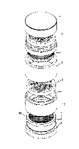
[0013] Fig. 1 is an exploded isometric view illustrating one embodiment
of an
herb grinder system.
[0014] Fig. 2 is an exploded plan view of the herb grinder system
illustrated in
Fig. 1;
[0015] Fig. 3A is an isometric view illustrating the lid member of the
embodiment illustrated in Fig. 1;
[0016] Fig. 3B is a plan view illustrating the bottom side of the lid
member;
[0017] Fig. 3C is a plan view illustrating the side of the lid member;
[0018] Fig. 3D is a section view taken along lines 3D-3D of Fig.3C;
[0019] Fig.4A is an isometric view illustrating the upper grinding plate
of
the embodiment illustrated in Fig. 1;
CA 2904961 2020-07-21
CA 02904961 2015-09-17
[00201 Fig. 4B is a plan view illustrating the bottom side
of the upper grinding plate;
100211 Fig. 4C is a plan view illustrating the side of the
upper grinding plate;
[0022] Fig. 4D is a section view taken along lines 4D-4D of
Fig. 4B;
[0023] Fig. SA is an isometric view illustrating the
tubular housing member of the embodiment illustrated in Fig. 1;
[0024] Fig. 5B is a plan view illustrating the bottom side
of the tubular housing member;
[0025] Fig. 5C is a plan view illustrating the side of the
upper tubular housing member;
[0026] Fig. 5D is a section view taken along lines 5D-5D of
Fig. 5C;
[0027] Fig. 6A is an isometric view illustrating the first
lower grinding plate of the embodiment illustrated in Fig. 1;
[0028] Fig. 6B is a plan view illustrating the bottom side
of the first lower grinding plate;
[0029] Fig. 6C is a plan view illustrating the side of the
first lower grinding plate;
[0030] Fig. 6D illustrates the top side of the first lower
grinding plate;
6
CA 02904961 2015-09-17
10031] Fig. 6E
is a section view taken along lines 6E-6E of
Fig. 6D;
[0032] Fig. 7A
is an isometric view illustrating the second
lower grinding plate of the embodiment illustrated in Fig. 1;
[0033] Fig. 7B
is a plan view illustrating the bottom side
of the second lower grinding plate;
100341 Fig. 7C
is a plan view illustrating the side of the
second lower grinding plate;
[0035] Fig. 7D
illustrates the top side of the second lower
grinding plate;
[0036] Fig. 7E
is a section view taken along lines 7E-7E of
Fig. 7D;
K0371 Fig. 8A
is an isometric view illustrating the sieve
section of the embodiment illustrated in Fig. 1;
[00381 Fig. 8E
is a plan view illustrating the bottom side
of the sieve section;
10391 Fig. 8C
is a plan view illustrating the side of the
sieve section;
[0040] Fig. 8D
is a section view taken along lines 8D-8D of
Fig. 8C;
[0041] Fig. 9A
is a top isometric view illustrating the
screen frame of the embodiment illustrated in Fig. 1;
7
CA 02904961 2015-09-17
[0042] Fig. 9B is a bottom isometric view illustrating the
screen frame of the embodiment illustrated in Fig. 1;
[0043] Fig. 9C is a plan view illustrating the side of the
screen frame;
100441 Fig. 9D is a plan view illustrating the top side of
the screen frame section;
[0045] Fig. 9E is a section view taken along lines 9E-9E of
Fig. 9C;
[0046] Fig. 10A is a top side view illustrating the sieve
screen;
[0047] Fig. 10B is a side view of the sieve screen;
[0048] Fig. 11A is a top view of the bottom cap member as
illustrated in Fig. 1;
[0049] Fig. 11B is a side view of the bottom cap member;
and
[0050] Fig. 11C is a section view taken along lines 11C-11C
of Fig. 11B.
DETAILED DESCRIPTION
[0051] In this description, references to "top", "bottom",
"upper", "lower", and the like merely refer to the relative
positions of the elements and parts of the grinder in the
figures, and do not restrict the positioning of the elements and
parts in actual use.
8
CA 02904961 2015-09-17
[0052] While the
present invention is susceptible of
embodiment in various forms, there is shown in the drawings and
will hereinafter be described a presently preferred embodiment
with the understanding that the present disclosure is to be
considered an exemplification of the invention and is not
intended to limit the invention to the specific embodiments
illustrated.
[005.3] Referring
to Figs. 1-11C, an herb grinder system 100
is illustrated. The herb grinder system is useful for grinding
herbs, tobacco, marijuana and the like. The
preferred
embodiment of the herb grinder system includes a tubular housing
2, a first lower grinding plate 4, an upper grinding plate
assembly 6 and a bottom cap member 8. At least one alternative
embodiment also includes a sieve section 10.
[0054] Referring
to Figs. 1, 2 and 5A-5D, the tubular
housing 2 is generally a tubular member including an internal
bore 12, an outer surface 14, a top surface 16 and a lower
surface 18. The lower
portion of the internal bore 12 has
internal engaging structures, illustrated herein as helical
threads 22, for attachment of a first lower grinding plate 4 as
well as the bottom cap member 8, or alternatively the sieve
section 10, each having conjugate external engaging structures.
This construction permits the assembly of multiple embodiments
utilizing the various component parts and assemblies. It should
9
CA 02904961 2015-09-17
be noted that, while the internal engaging structures are
illustrated herein as threads, other engaging structures such as
bayonet mounts, multi lead threads, quick releases and the like
may be utilized without departing from the scope of the
invention. In a most preferred embodiment, the internal bore 12
of the tubular housing member includes a shoulder surface 24
therein; the shoulder surface is positioned above the internal
engaging structures to provide a surface against which a portion
of the upper surface 32 of the first grinding plate 4 abuts when
secured within the internal bore. This
construction provides
support to the lower grinding plate 4 from the outer perimeter
surface 36 as well as from the upper surface 32 to prevent
unwanted rotation of the lower grinding plate, and insures that
the grinding plate is secured perpendicularly within the bore.
The construction also prevents finely ground particles from
being trapped between the outer perimeter surface of the
grinding plate and the bore wall 12. The top portion 26 of the
internal bore 12 is preferably provided with a smooth surface
for cooperation with the upper grinding plate assembly 6. Some
embodiments may include deflectors 28 for deflecting the
material being ground back into the central portion of the
grinder.
100551 Referring
to Figs. 1, 2, 6A-6E, and 7A-7E, the first
lower grinding plate 4 and second lower grinding plate 64 are
CA 02904961 2015-09-17
illustrated. The first
and second lower grinding plates 4, 64
include a plate portion 30 having an upper surface 32, a lower
surface 34 and an outer perimeter surface 36. The outer
perimeter surface 36 has conjugate engaging structures,
illustrated herein as helical threads 22, for cooperation with
said internal engaging structures 22 to secure the first or
second lower grinding plate at a substantially perpendicular
orientation with respect to the internal bore 12 at a position
below the top surface 16 of the tubular housing member (Fig. 5)
and to prevent unwanted rotation thereof. The upper surface 32
of the first and second lower grinding plates 4, 64 each have a
plurality of upstanding blades 38 integrally formed to the
plate. In a most preferred embodiment, each blade 38 includes a
modified diamond pattern when viewed from the top, whereby at
least two side surfaces 40 of each modified diamond include at
least one concave radius. The concave radius 41 is positioned
along the side surfaces to cause each distal point 42 of each
blade to be a concave beveled cutting edge. A
plurality of
sized apertures 44 are positioned proximate to the blades and
extending through the plate for controlling the grind size that
is allowed to pass through the plate. In at
least one
embodiment, the apertures include more than one size to allow
different sized grinds to pass through the plate. In a most
preferred embodiment, the apertures in the second lower grinding
11
CA 02904961 2015-09-17
plate 64 are all smaller than the apertures in the first lower
grinding plate to provide a smaller ground material.
pm] Referring
to Figs. 1, 2, 3A-3D and 4A-4D, the upper
grinding plate assembly 6 is illustrated. The upper
grinding
plate assembly 6 includes the upper grinding plate 54 and a lid
member 66. The upper
grinding plate 54 includes an upper
surface 46, a lower surface 48, an outer diameter surface 50 and
a pilot portion 52. The pilot portion 52 is sized and shaped to
fit within the internal bore 12 while allowing rotation of the
upper grinding plate assembly 6 with respect to the tubular
housing member 2. The lower
surface 48 of the upper grinding
plate assembly 6 includes a plurality of outwardly extending
blades 38 positioned to pass between said upstanding blades 38
of the lower grinding plate 4 when the upper grinding plate is
rotated. In a most preferred embodiment, each blade 38 includes
a modified diamond pattern when viewed from the top, whereby at
least two side surfaces 40 of each modified diamond include at
least one concave radius 41. The
concave radius is positioned
along the side surfaces to cause each distal point 42 of each
blade to be a concave beveled cutting edge. The pilot portion
52 of the upper grinding plate 54 is cylindrical in shape,
having an outer diameter 56 that is sized to fit within the top
portion of said internal bore 12 of the tubular housing member
2. In a preferred embodiment, the outer diameter surface 56 of
12
CA 02904961 2015-09-17
the pilot portion 52 includes a plurality of burnishing rings 58
separated by debris rings 60. The
debris rings 60 having a
smaller diameter than the burnishing rings 58. In this manner,
finely ground material is prevented from binding rotation of the
upper grinding assembly. The
burnishing rings 58 provide
precise positioning while pushing debris into the debris rings
60, which can be cleaned after the grinding is completed. In at
least one embodiment, the upper grinding plate 54 includes a
magnet 62 positioned in a central portion of the lower surface
48. The first
lower grinding plate 4 includes a magnet 62
positioned in a central portion thereof, so that the magnets
attract each other when said pilot portion 52 of the upper
grinding plate assembly 6 is positioned within the top portion
of the internal bore 12 of the tubular housing member 2.
100571 The upper
grinding plate assembly 6 includes a lid
member 66 constructed and arranged to cooperate with an upper
portion 26 of the outer diameter surface 14 of the' upper
grinding plate assembly 6. The lid
member 66 is cup shaped
including an inner wall 68, the inner wall including helical
threads for cooperation with mating helical threads on the upper
portion of the upper grinding plate assembly. In at least one
embodiment, the threads have sufficient length to cooperate with
the second lower grinding plate 64 for storage within the lid
member, while the upper surface 46 of said upper grinding plate
13
CA 02904961 2015-09-17
assembly is constructed to be concave to provide an upper
grinding plate storage area enclosable with the lid member.
K058] Referring
to Figs. 1, 2, and 11A-11C, a bottom cap
member 8 is illustrated. The bottom cap member 8 has an outer
perimeter surface 74, a top surface 76 and a bottom surface 78.
The outer perimeter surface 74 has conjugate engaging
structures, illustrated herein as threads, 22 for cooperation
with said internal engaging structures within said tubular
housing member 2 to secure said bottom cap member 8 at a
substantially perpendicular orientation with respect to said
internal bore 12 at a position juxtaposed to said lower surface
18 of said tubular housing member 2, having a gap or concavity
between said top surface 76 of said bottom cap member 8 and said
lower surface 34 of said lower grinding plate 4.
[0059] Referring
to Figs. 1, 2, 8A-8D, 9A-9E and 10A-10B, a
sieve section 10 is illustrated. The sieve
section 10 is
insertable between the lower surface 18 of the housing member 2
and the bottom cap member 8. The sieve
section 10 is
constructed and arranged to separate a predetermined particle
size of ground material from the remaining ground material using
a screen 80. The sieve
section 10 is tubular in shape having
an upper surface 82, a lower surface 84, an inner bore surface
86 and an outer surface 88. A screen assembly 90 is releasably
secured within the inner bore surface. The screen
assembly 90
14
CA 02904961 2015-09-17
includes a screen 80 and a screen frame 92; the screen frame 92
extending around the perimeter of the screen 80 with the screen
frame retaining the screen within the inner bore surface. In a
preferred embodiment, the screen frame 92 includes threads on an
outer diameter 94 thereof, the inner bore surface 86 of the
sieve section 10 including conjugate threads for cooperation
with the outer diameter of said frame. Tabs 96 are provided to
allow the screen frame to be inserted and removed from the sieve
section. It should be noted that the present device may be
manufactured in a variety of sizes to accommodate different
volumes of material to be ground. It should also be noted that
the preferred material for construction of the herb grinding
system is metal, and more preferably aluminum having a T6 or T7
temper. However, other material including plastic, carbon fiber
or suitable combinations thereof may be utilized without
departing from the scope of the invention. It should
also be
apparent to those skilled in the art that screens of various
mesh may be utilized to separate out desirable sizes of ground
material.