Note : Les descriptions sont présentées dans la langue officielle dans laquelle elles ont été soumises.
CA 02905754 2015-09-11
WO 2014/159400
PCT/US2014/023419
INFINITY SHAPE COIL FOR SPIRAL SEAMS
BACKGROUND
6 Field of the Invention
The present invention relates to seams and seaming materials used in
industrial fabrics.
More specifically, the present invention relates to seams and seaming
materials to reduce seam
wear by reducing seam caliper, particularly for reducing the seam caliper at
or below the fabric
surface planes at least when the fabric is under tension.
Industrial fabrics means endless structures in the form of a continuous loop,
and used
generally in the manner of conveyor belts. As used throughout this disclosure,
"industrial
fabrics" refers to fabrics configured for modem papermaking machines, and
engineered fabrics,
which may be used in the production of nonwovens. Modem papermaking machines
employ
endless belts configured for use in the forming, pressing, and drying areas,
as well as process
belts which may also be used in sections of the modern papermaking processes,
such as in the
pressing section. Engineered fabrics specifically refers to fabrics used
outside of papermaking,
including preparation machinery for paper mills (i.e., pulp), or in the
production of nonwovens,
or fabrics used in the corrugated box board industries, food production
facilities, tanneries, and
in the building products and textile industries. (See, for example, Albanv
International Corp.'s
2010 Annual Report and 10-K, Albany International Corp., 216 Airport Drive,
Rochester, NH
03867, dated May 27, 2010.)
in the formation of industrial fabrics, the base fabric may take a number of
different
forms. For example, the fabric may be woven endless or flat woven, and
subsequently rendered
into an endless form with a seam. Industrial fabrics, as endless loops, have a
specific length,
measured circumferentially therearound, and a specific width, measured
transversely thereacross.
In many applications, industrial fabrics must maintain a uniform thickness, or
caliper, to prevent,
for example, premature wear in areas where a localized thickness is greater
than in the immediate
surrounding area, or marking of a manufactured good carried thereon or
contacted thereby.
- 1 =
CA 02905754 2015-09-11
WO 2014/159400
PCT/US2014/023419
Industrial fabrics and engineered fabrics, used respectively in modem
papermaking
machines and in the production of nonwovens, for example, may have a width
from about 5 feet
to over 33 feet, a length from about 40 feet to over 400 feet, and weigh from
approximately 100
pounds to over 3,000 pounds.
Because of their size and weight, and the configuration of the industrial
machines on
which they are used, in many applications it is often convenient to install
industrial fabrics on the
appropriate machine as a flat article having lengthwise and widthwise edges,
and joining the
widthwise edges with a seam, for example, to form a continuous belt. When
installed flat and
formed into a continuous loop structure on an industrial machine, such
industrial fabrics may be
io known as on-machine-seamable fabrics.
Seams have presented problems in the function and use of on-machine-seamable
fabrics
in at least in that they may have a thickness, or caliper, that is different
from that of the industrial
fabric edges the seam is joining. Variations in thickness between the seam and
the fabric edges
can lead to marking of the product carried on the fabric. Seam failure may
also result if the seam
15 area has a greater thickness than the fabric edges as the seam is
exposed to machine components
and resulting abrasion or friction.
To facilitate seaming, many fabrics for industrial use have seaming loops
formed on two
opposite edges of the fabric to be joined. For example, seaming loops
themselves may be
formed from the warp yarns of a flat woven fabric. Seaming loops can be formed
by removing
20 weft yarns at the ends of the fabric to free end portions of warp yams.
Loops may also be
formed by reintroducing (re-weaving) the free end portions of the warp yarns
into the fabric.
A seam is formed by bringing the two ends of the fabric together, by
interdigitating and
alternating the seaming loops at the two ends of the fabric, to align the
openings in the loops to
form a single passage, and by directing a pin, or pilule, through the passage
to lock the two ends
25 of the fabric together.
Alternatively, a seaming spiral may be attached to the seaming loops at each
of the two
ends of an industrial fabric. An example of this method is shown in U.S.
Patent No. 4,896,702 to
Crook in which a multilayer industrial fabric is formed. As shown, a tubular
base fabric is
formed, flattened to form edges at the lengthwise extremities of the fabric,
and cross machine
30 direction yams in the area of the edges are removed. A spiral coil is
attached to the seaming
-2-
CA 02905754 2015-09-11
WO 2014/159400
PCT/US2014/023419
loops of the industrial fabric. Alternately, the seaming spirals may be
connected to the seaming
loops by at least one connecting yarn. The coils of the spirals at the two
ends of the industrial
fabric may again then be interdigitated and joined to one another on the
machine with a pintle to
form a seam usually referred to as a spiral seam.
In other alternative solutions, seam reinforcing rings may be attached to
edges of a press
fabric to be joined as shown in U.S. Patent No, 7,273,074 to Hansen. According
to embodiments
of Hansen, the rings provide reinforcement to the seam by functioning as a
back-up to the
seaming loops and including CD (cross-machine direction) yarns in the formed
seam, thereby
increasing the strength of the seam. The rings also provide improved flex
resistance to the seam.
Hansen suggests a desirable feature of a seam in a press fabric is
permeability to water and air
that is the same as the rest of the fabric.
In a warp loop scam, the rows of loops are formed of extended edge loops of
warp yams
in the fabric structure of the fabric. In a spiral seam, each row of loops is
instead formed of a
separate, preformed yarn spiral, which is extended along and attached by means
of a CD pirate
connecting the spiral, intermeshed with the machine direction yams, such as
warp yams, to the
seam edge of the fabric, The coils of the spirals at the two ends of the
fabric may again be
alternatingly interdigitated and joined to one another on the machine to form
a spiral seam.
Alternatively, the spiral can be attached to the industrial fabric by a number
of cross-
machine direction (CD) yarns being raveled a distance from the widthwise seam
edge revealing
zo machine direction (MD) yarn lengths Then MD yams are rewoven into the
fabric, forming
loops. The spirals are inserted into the thus formed loop edge portion and
connected to the loops
by one or more pintles. Then the spirals on each fabric edge are
interdigitated and a pilule
inserted to form the seam.
Regardless of how the spiral is attached, a spiral seam on an industrial
fabric usually
comprises two spirals, one along each fabric edge, which, when joining
together the fabric edges,
are interdigitated and aligned with each other so as to form a single passage
configured to accept
a pintle, wire or the like, to join the fabric edges.
A seam is a critical part of a seamed fabric, since uniform physical
characteristics of the
industrial fabric are usually required. lithe seam itself is not structurally
and functionally nearly
identical to the industrial fabric, modification of the seam area may be
necessary to obtain
-3-
CA 02905754 2015-09-11
WO 2014/159400
PCT/US2014/023419
characteristics sufficiently similar to the main portion of the industrial
fabric for the intended
application.
SUMMARY OF THE INVENTION
The present invention provides seam elements and the use of the seam elements
to join
ends of an industrial fabric in forming a continuous loop. Also provided is an
endless structure
formed from an industrial fabric and seam elements according to this
invention.
According to embodiments of the invention, low profile seam elements are
disclosed
which can eliminate, or at least substantially reduce, seam wear by reducing
the seam thickness,
io or caliper, to a level which is even with, or even below, the fabric
surface plane when the fabric
is under tension in use.
As used herein, "low profile" seams, or seam elements, or seaming elements,
are seams
or components of seams which have a profile, defined by the caliper, or
thickness, of the seam or
seam elements, which is as thin as, or thinner than, the edges of the fabric
the seam is used to
join, at least when the seam is under tension substantially transverse to the
seam axis, as when
the fabric is in use. The profile or thickness is that of the seam or seam
element when viewed
along the axis of the seam.
According to aspects of this invention, seam elements for use in joining a
first end and
second end of an industrial fabric are provided. At least one of the elements
provides an
Infinity coil," so named because an axial view of the coil resembles an
infinity symbol,
commonly, a figure-eight shaped curve, or, mathematically, a lenmiscate. As
such, each element
has two loops, one to attach the seaming element to the industrial fabric. The
second loop of the
first seaming element is provided to interdigitate with the second loop of the
second seaming
element, and accept a pintle, or pin, through a passage formed by the
interdigitated loops.
According to embodiments of this invention, a fabric can be woven flat, or
configured to
be fiat after weaving, with opposing parallel edges, and formed into an
endless loop by joining
opposite edges of the fabric article using seaming elements according to this
invention.
When elements are referred to as joined or joining, or forming a joint, either
with regard
to fabric edges or to another element, the joint formed is generally a pinned
connection in which
the components of the joint (element and fabric or element and element) are
generally free to
-
CA 02905754 2015-09-11
WO 2014/159400
PCT/US2014/023419
rotate to a degree about an axis of the joint. Characteristics of elements, or
the "infinity coil"
joined to a fabric edge or to each other will become apparent in the
description that follows.
As used in this application, an infinity coil is a shaped coil of material
which can, for
example, be a monofilament, twisted multifilament, coated or uncoated, or
coated or uncoated
metal wire, comprising two loops formed by the material passing alternately
over and under a
pair of parallel linear coplanar support members and crossing in the space
between the support
members. The support members may be, for example, a double mandrel or a spiral
link-type
forming apparatus. The loops may be substantially the same size and shape,
although differing
sizes and shapes are anticipated for certain applications. In forming an
infinity coil, a double
la mandrel is provided comprising two adjacent support members, generally
parallel and coplanar
to each other, and spaced apart from each other with a center-to-center
spacing proportional to
the desired center-to-center distance of the loops of the infinity coil. A
material, for example, a
polyester monofilament, passes over a first mandrel, passes through the space
between the two
mandrels, passing below and then around and over the top of the second
mandrel, back through
the space between the mandrels and under the first mandrel. Thus, in a
complete turn, the
seaming material used to form an infinity coil traces the basic curved shape
of a lemniscate, or
figure-eight, or infinity symbol. Subsequent infinity coils turns are formed
in the same way,
offset axially from the previous infinity coil turn. Coil turns can be added
until the desired
number of coils is formed or the desired axial length, which may be
proportional to the number
of coils, results.
Other methods may be used to form the infinity coil as will be apparent from
the
following disclosure. -
Infinity coils may be used to join fabric articles, or to join fabric articles
to form
industrial fabrics as continuous loops of material. When joined to fabric
edges or joined to
another infinity coil, the joint formed with the disclosed infinity coils is a
pinned connection
allowing the elements making up the joint to pivot about an axis of the joint
to a degree. Other
uses for the infinity coils are disclosed or apparent from the following
description.
It is noted that in this disclosure and particularly in the claims, terms such
as
"comprises," "comprised," "comprising" and the like can have the meaning
attributed to it in
U.S. Patent law; e.g., they can mean "includes," "included," "including" and
the like.
== 5 -
CA 02905754 2015-09-11
WO 2014/159400
PCT/US2014/023419
An object of the disclosed techniques is the production of a seam for use in
forming an
industrial fabric in which the seam 'elements are used to join parallel width-
wise edges of a fabric
to form an industrial fabric.
For a better understanding of the techniques disclosed herein, its advantages
and specific
objects obtained by its use, reference is made to the accompanying descriptive
matter in which
preferred, but non-limiting, embodiments are illustrated.
BRIEF DESCRIPTION OF THE DRAWINGS
The following detailed description, given by way of example and not intended
to limit the
invention to the disclosed details, is made in conjunction with the
accompanying drawings, in
which like references denote like or similar elements and parts, and in which:
Fig. 1 is an axial view of a conventional coil;
Fig. 1A. is a perspective view of the conventional coil of Fig. 1;
Fig, 2 is an axial view of the coil of Fig. I formed on a single mandrel;
Fig. 3 is an axial view of conventional toil seam;
Fig. 4 is an axial view of the conventional coil seam of Fig. 3 under an
increased tensile
load transverse to the axis of the seam;
Fig, 5 is an axial view of an infinity coil according to embodiments of this
invention;
Fig. 5A is a perspective view of the infinity coil of Fig. 5;
Fig. 58 is a perspective view of a separate infinity seam loop according to an
embodiment of the invention;
Fig. 5C is a perspective view of a separate infinity seam loop according to
another
embodiment of the invention;
Fig. 6 is an axial view of the infinity coil of Fig. 5 formed on a double
mandrel;
Fig. 7 is an axial view of an infinity coil seam according to embodiments of
the
invention;
Fig. 8 is an axial view of the seam of Fig. 7 under an increased tensile load
transverse to
the axis of the seam;
Fig, 9 is a plan view of infinity coils according to embodiments of the
invention joined to
fabric edges;
Fig. 10 is a plan view of the infinity coils of Fig. 9 with coils
interdigitated;
-6-
CA 02905754 2015-09-11
WO 2014/159400
PCT/US2014/023419
Fig. 11 is a plan view of the infinity coils of Fig. 10 with a pintle inserted
to join fabric
edges; and
Fig. 12 is an axial view of an infinity coil seam joining fabric edges in
accordance with
an embodiment of the invention.
DETAILED DESCRIPTION
Embodiments of the invention are described below with reference to the
accompanying
drawings which depict embodiments of the disclosed infinity coil and exemplary
applications
thereof. However, it i to be understood that application of the disclosed
infinity coil is not
lo limited to those embodiments illustrated. Also, the invention is not
limited to the depicted
embodiments and the details thereof, which are provided for purposes of
illustration and not
limitation.
The present invention relates to low profile seams in industrial fabrics, and
includes
engineered fabrics and fabrics used in papermaking, in which wear of the seam
is eliminated or
at least reduced by reducing the thickness of the seam to no more than the
thickness of the fabric
joined by the seam, at least when the seam is under tension generally
perpendicular to its axis, as
when a seamed fabric is in use. That is, when under a tensile load, the seam
is as thin as, or
thinner than, the fabric joined by the seam.
The present invention relates to seams in fabrics formed into continuous loops
for use in
zo industrial applications. Specifically, the present invention relates to
seams formed in fabrics
installed on an industrial machine, commonly referred to as on-machine-
seamable fabrics.
The present invention also relates to a process for producing such an improved
seam in
an industrial fabric.
"Industrial fabrics," which include paper machine clothing discussed above,
means
endless structures in the form of a continuous loop, and used generally in the
manner of
conveyor belts. "Industrial fabrics" as used in this disclosure refers to
fabrics configured for
modern papermaking machines, and engineered fabrics. Engineered fabrics
specifically refers to
fabrics used outside of papermaking, including preparation machinery for paper
mills (i.e., pulp),
or in the production of nonwovens, or fabrics used in the corrugated boxboard
industries, food
production facilities, tanneries, and in the building products and textile
industries.
-7-
CA 02905754 2015-09-11
WO 2014/159400
PCT/US2014/023419
Seams in on-machine-seamable fabrics have been problematic in that the
caliper, or
thickness, of the seam region often varies from the caliper of the fabric
edges joined by the seam.
The problems typically encountered include, but are not limited to, wear of
the seam loops or
elements and marking of the product carried by the fabric if the seam area is
thicker than the
.5 fabric edges joined. Wear of the seam material caused by friction or
abrasion from contact with
machine components can lead to further marking of the product carried by the
fabric, and also
may lead to catastrophic failure of the fabric. By providing a low profile
seam with a seam
thickness under tension equal to or less than the thickness of the fabric
edges being joined,
embodiments of the present invention can eliminate, or at least reduce,
frictional and abrasive
wear of the seam.
The present invention also relates to the coils used to form seams in
industrial fabrics,
that is, the invention relates to industrial fabric seaming coils. The coils
may be formed from a
monofilament or twisted multifilament, coated or uncoated, made from a polymer
or polymers,
such as polyester, a coated or uncoated metal wire, or from other materials
known in the art to be
suitable for a seam in an industrial fabric. The coils may be formed as a
continuous piece having
an appropriate length for the length of the seam to be formed, as measured as
the cross machine
direction (CD) width of the fabric. In some instances, a coil formed as a
continuous piece may
have a length the same length as, or nearly the same as, the length of the
seam to be formed.
Other coil lengths may be useful, such as lengths less then the length of the
seam, or greater than
the length of the seam and trimmed to an appropriate length. In other
embodiments, the coils
may be individual pieces of seam material formed into separate scam loops,
with a number of
individual seam loops arranged along the length of each fabric edge to be
joined.
Coils in this application are illustrated as having two enclosed interior
portions or nodes,
when viewed along the axis of the coil, for ease of illustration. This
corresponds with the
common infinity symbol or the mathematical lemniscate. However, coils of more
than two
enclosed interior portions or nodes are anticipated, and are also referred to
as infinity coils
because they comprise coil turns forming at least one infinity symbol or
lemniscate. Such coils
lend themselves to similar manufacturing techniques using a forming apparatus
with a number of
support members corresponding to the number of desired nodes. Infinity coils
with more than
two nodes have industrial uses, for example, uses similar to those disclosed
for the two-node
coils.
-8-
CA 02905754 2015-09-11
WO 2014/159400
PCT/US2014/023419
Other embodiments of the present invention can provide an industrial fabric
with uniform
physical characteristics throughout the fabric, particularly from edge to edge
across the seam
region, that is, across the width of the fabric (CD) in the area of the seam,
including the seam
itself.
A loop I for a conventional, prior art spiral coil spiral seam, as shown in an
axial view in
Fig. I and in a perspective view in Fig. IA, has a curved shape, approximating
a circular or
ovular shape. Successive coils are similarly shaped and approximately coaxial,
extending into
the paper as illustrated. Typically, such coils are formed by placing
successive coaxial coils of
material, for example a polyester monofilament, on a single mandrel 3 as shown
in Fig. 2. The
io open interior portion 2 is similarly shaped and proportional in size to
the mandrel 3 upon which
it is formed. Although an ovular shaped mandrel is shown, other shapes may be
used for the
mandrel.
The seaming materials may be a monofilament or a twisted multifilament, coated
or
uncoated, formed from one or more polymers such as polyester, or metal wire,
or other material
known in the art. The seaming materials or individual coils may be coated or
treated as required
by the specific application to have desirable properties. in cross section,
the spiral coils may be
round, rectangular, oval, flattened, or other noncircular shapes.
When two coils la and lb are joined to opposite fabric edges (not shown) and
configured
to form a spiral coil seam illustrated generally as 5 in Fig. 3, at least some
of the open interior
portions 2 of the two spiral coil loops I align to form a passage 4 to accept
a pintle or pin 6,
forming a seam joining the two fabric edges. The two conventional spiral coil
loops 1 are
generally free to pivot or rotate about the axis of the pintle which
substantially corresponds with
the axis of the seam 5. Often the spiral coil seam thickness is slightly
greater than the joint
thickness before tension is applied. The thickness or caliper Cl of the fabric
edges joined
corresponds with the caliper of the coil loops as shown in Fig. 3.
When the seam 5 of Fig. 3 is placed in tension perpendicular to the axis of
the seam,
which corresponds with the axis of the pintle 6, that is tension in the length
direction of the
industrial fabric, conventional spiral coil loops la and lb tend to elongate
slightly in the direction
of the tension indicated by the an-ow in Fig. 4, and contract slightly a
distance in the direction
perpendicular to the tension. That is, in the case of oval coils, the major
diameter of the coils
lengthens and the minor diameter shortens.
-9-
CA 02905754 2015-09-11
WO 2014/159400
PCT/US2014/023419
Further, the size of the single passage 4 formed by the aligned interior
portions 2
decreases and approaches the size of the pintle 6 as the conventional coils I
are displaced
longitudinally and elongate. The conventional coil loops I thus joined remain
free to pivot or
rotate about the longitudinal axis of the pintle 6.
Accordingly, the initial seam length Li in Fig. 3 lengthens to L2 of Fig. 4
and the
thickness of the seam changes by a small amount AC which is equivalent to the
difference Cl -
C2. When Cl is greater than C2, the seam 5 is sometimes referred to as
experiencing "seam
thinning," as the seam decreases slightly in thickness from a first tensile
state to a second tensile
state. Conventional spiral coils are purposely designed to have minimal
elongation. The spiral
coils are usually quite stiff. Thus, the degree of "seam thinning" as defined
here is small. As
drawn in Fig, 4, the total amount of the seam thinning is shown as AC on one
side of the seam 5
only for ease of illustration. In practice, approximately even amounts of seam
thinning would be
present on each side of the thickness of seam 5.
According to embodiments of the present invention, a low profile seam element
is
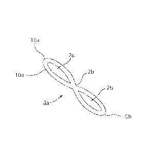
is provided in the form of the infinity coil 8 in Figs. 5 and 5A, formed as
a figure-eight shaped
curve, or a lemniscate, resembling a symbol commonly used to represent
infinity, 00. According
to embodiments of the invention, a continuous helical infinity coil as
illustrated in Figs. 5 and 5A
is an infinity coil formed from a continuous strand of material., When viewed
parallel to the axis
X-X of the coil, the continuous helical infinity coil will appear to have two
closed curves
forming first and second infmity coil loops 10a and l01), respectively, with
first and second open
interior portions 2a and 2b, respectively. Coils according to embodiments of
the invention may
also have more than two open interior portions, yet are still referred to as
infinity coils
throughout the disclosure. For example, a seaming material can be formed as
three or more
closed curves forming three or more adjacent coil loops, the three or more
coil loops enclosing
respective open interior portions, and intersection regions between adjacent
coil loops in which
seaming material forming a coil loop intersects with material forming an
adjacent coil loop. The
seaming material can be: a. molded to form the three or more adjacent coil
loops, b. extruded in
a substantially linear form and mechanically deformed into the three or more
adjacent coil loops,
or c. extruded such that extruded material forms the three or more adjacent
coil loops either by
moving an extruding head or by moving a receptacle upon which the material is
extruded.
- to
CA 02905754 2015-09-11
WO 2014/159400
PCT/US2014/023419
The material used to form infinity coils may be any of the materials known in
the art as
suitable for seams in industrial fabrics, for example a polyester
moriofilament, and may have any
suitable cross section. Circular cross sectional shapes of the material may be
used. Additionally,
in non-limiting examples, other cross section shapes may be used, such as
oval, rectangular,
s triangular, flattened, star-shaped, or other non-circular shape. Other
cross sectional shapes may
be used depending upon particular requirements.
Fig. 5A illustrates an infinity coil 8 according to embodiments of the
invention. The coil
8 comprises first and second loops 10a and I Ob. As shown, a plurality of
loops 10a, 10b can
extend along coil axis X-X in the direction of coil length L Coil 8 may have
any combination of
number of loops 10a, 10b, and coil length L as determined by the particular
application.
Width W of the coil is taken perpendicular to, or generally perpendicular to,
the axis X-X
and is the maximum dimension between the outermost portion of loop 10a and the
outermost
portion of adjacent loop 10b. The width W may be the same, or substantially
the same, for all
adjacent loop pairs 10a, I Ob.
Within each of the coil loops 10a and 10b are open interior portions 2a and
2b,
respectively. The open interior portions 2a and 2b have axes Xa and Xb, which
are parallel, or
generally parallel, to coil axis X. In embodiments of the inventive coils, the
axis of all, or
substantially all, first open interior portions 2a of first loops 10a are
collinear, Similarly, in
embodiments of the invention, the axis of all, or substantially all, second
open interior portions
2b of second loops 10b are collinear. In some embodiments, axes X, Xa and Xb
may be
coplanar.
In addition to the plurality of loops 10a and 10b shown in Fig. 5A,
embodiments of the
invention include individual infinity coil elements 8a comprising at least one
complete loop I Oa
and one complete loop 10b as illustrated in Fig. 58. Individual coil elements
8a may be formed
by cutting the coil element of Fig. 5 in an appropriate location to form two
complete loops and
joining the free end portions 2c to form the individual coil element. Portions
of the seam
material 2d which cross, with one portion of the coil crossing over the other,
or intersect,
between the open interior portions 2a and 2b may be affixed to each other by
adhesive, welding,
bonding, or other known methods after formation of the coil 8a. Thus, one loop
10a and one
loop I Ob are formed, each loop forming a completely closed interior portion
2a or 2b,
respectively, of individual coil element 8a. Alternately, other techniques may
be employed in
CA 02905754 2015-09-11
WO 2014/159400
PCT/US2014/023419
forming individual coil elements 8a, as shown, in Figs. 5B and 5C. Individual
coils can be
formed from molten or softened polymers or resins by known plastic fabrication
methods. Such
methods include, as non-limiting examples, injection molding, extrusion
molding, compression
molding, transfer molding, or casting. In some embodiments, the portion of
seam material 2d
s may intersect on the same, or substantially the same, plane between the
open interior portions 2a,
2b of the coil 8a as illustrated in Fig. 5C. Thus the portion of seam material
between the open
interior portions 2a, 2b may be integrally formed with loops 10a and 1.0b. The
individual coil
elements 8a thus formed are comprised of one loop I Oa and one loop 10b,
joined at 2d, each loop
forming a completely closed interior portion 2a or 2b, respectively.
io As used herein, the term "infinity coil" includes both continuous
helical infinity coils and
individual infinity coil elements unless a distinction is made for clarity.
Continuous helical infinity coils 8 can be formed on a double mandrel coil
former
comprising generally parallel coplanar mandrels 3a and 3b as shown in Fig. 6.
Infinity coils 8
can be formed, for example, by passing material, for example, polyester
monofila.ment, over the
15 top of a first mandrel 3a, through the space between the two mandrels,
below and then around
and over the top of the second mandrel 3b, back through the space between the
mandrels and
under the first mandrel 3a. Thus the coil forming material traces the path of
a figure-eight as the
infinity coils 8 are formed around mandrels 3a and 3b. This pattern can
continue with each coil
turn offset axially from the previous, until the desired number of coils, or
the desired axial length
zo of the infinity coil 8, which may be proportional to the number of
coils, is formed. In this
manner a seaming element comprising a plurality of infinity coils 8 can be
formed with loops
10a and I Ob, with each loop 10a formed coaxially with previous loops 10a and
each loop 1 Ob
formed coaxial!), with previous loops 10b.
The two individual mandrels 3a and 3b comprising the double mandrel are
illustrated as
25 having a round cross section for ease of illustration only. The mandrels
may be of any suitable
shape to yield the desired shape of the infinity coil loops 10a and 1 Ob. The
mandrels are also
shown as substantially the same size for ease of illustration. However, the
mandrels I Oa and 10b
may be the same, or substantially the same size, or one mandrel may be larger
than the other, or
differently shaped, as desired.
30 Other techniques may be employed in forming the inventive infinity
coils. For example,
the infinity coil could be molded from a molten or softened polymer or resin
as one piece using
-12-
CA 02905754 2015-09-11
WO 2014/159400
PCT/US2014/023419
known molding methods, such as, for example, injection molding, extrusion
molding,
compression molding, transfer molding, or casting. The material used for the
coil could also be
extruded in a linear or near linear form and mechanically deformed into the
lemniscate or infinity
shape, with or without the application of heat. The material could also be
extruded in a manner
such that the extruded material forms the lemniscate or infinity shape either
by moving the
extruding head or by moving the bed or receptacle upon which the material is
extruded.
In forming an infinity coil seam 12 as illustrated in Fig. 7, a first infinity
coil 8a is joined
with a first fabric edge (not shown) and a second infinity coil 8b is joined
with a second fabric
edge (not shown) via respective loops 10a of the infinity coils 8a and 8b. In
the non-limiting
la embodiment illustrated in Fig. 7, infinity coils 8a and 8b each include
loops 10a to be joined to
first and second fabric edges (not shown) using a known method of joining,
such as a pintle.
Loops 10b from first infinity coil 8a are interdigitated with loops I Ob from
second infinity coil
8b such that the open interior portions 2b of the loops 10b at least partially
align and ferm a
single passage 4 in the seam 12. The passage 4 may be sized to allow a pintle
or pin 6 to pass
is through the aligned open interior portions 2b of loops 10b, joining the
coil seam elements 8a and
8b. The loops 10b from the first and second infinity coil loops 8a and 8b may
interdigitated and
alternate, i.e., altematingly interdigitate, one loop from a first coil, the
next loop from a second
coil, followed by a loop from the first coil in a repeated pattern along the
length of the seam.
However, other patterns of interdigitation may be used as required.
20 In an embodiment, infinity coil seam 12 is formed from one or more first
infinity
continuous helical coils 8a disposed axially end-to-end and one or more second
continuous
helical infinity coils 8b disposed axially end-to-end in the CD direction of
respective fabric
edges. In another embodiment, infinity coil seam 12 is formed from a plurality
of first individual
infinity coil elements disposed side-by-side so the open interior portions
thereof substantially
26 align with one another and a plurality of second individual infinity
coil elements disposed side-
by-side so the open interior portions thereof substantially align with one
another in the CD
direction of respective fabric edges.
One benefit of the disclosed infinity coil seam 12 is the additional seam
thinning realized
when the seam and the fabric are placed in tension generally perpendicular to
the seam axis, in
30 the length direction ofthe industrial fabric, as compared to a prior art
seam. As illustrated in Fig.
7, the thickness of the infinity coil loops 10a and 10b is not greater than
the thickness Cl of the
- J3 -
CA 02905754 2015-09-11
WO 2014/159400
PCT/US2014/023419
fabric. As illustrated in Fig. 8, the seam 12 is under tension, and the
thickness C2 of the infinity
coil loops 10a and I Oh is desirably less than the thickness Cl of the fabric.
The seam thinning as
illustrated is a desirable characteristic as it places the infinity coil 8 at
or below the plane of the
industrial fabric. The distance AC as shown in Fig. 8 is the total amount of
seam thinning the
coil experiences. In practice, the amount of seam thinning would be
approximately evenly
distributed throughout the thickness, i.e. the top and bottom surfaces, of the
infinity coil.
According to embodiments of the present invention, an industrial fabric may be
formed
from a fabric with the disclosed infinity coils used to form a seam between
opposite edges of the
fabric. As illustrated in Fig. 9, infinity coils 8a and 8b may be joined to
opposite fabric edge
io portions 14a and 14b in preparation for joining the edge portions
together. As illustrated in Fig.
9, infinity seam loops 10a of infinity coils 8a and 8b are joined to the
fabric edge portions 14a
and 141,. Joining of the infinity loops to the fabric may be accomplished in
any way known to
the art, for example, a pintle or pin may be used to join the infinity loops
10a to loops formed at
the fabric edges, or fabric yarns may be woven through the infinity coil loops
10a and
reintroducing the yarns to the fabric, or the infinity loops may be joined to
the fabric by sewing,
or by other known techniques.
Having attached the infinity coils 8a and 8b to the fabric edge portions 14a
and I4b,
respectively, the fabric edges may be drawn toward each other such that
infinity loops I Ob of
infinity coil 8a may interdigitate with loops 10b of infinity coil 8b and open
interior space 2b of
infinity loops 10b at least partially align with each other to form a single
passage (reference 4 in
Fig. 7) as illustrated in Fig. 10.
A pintle or pin 6 may be passed through the formed passage and through all, or
substantially all, of the infinity coil loops 10b joining infinity coil 8a
with infinity coil 8b. In
instances in which infinity coils 8a and 8b are joined to opposite edges of
the same fabric article,
26 an industrial fabric 16 is formed as a continuous loop. As shown in Fig.
12, a pintle or pin or
wire 6 may be used to join each infinity coil to the fabric edge portions 14a
and 14b, although
any known joining technology could be used.
As discussed above, the joining of a first infinity loop 8 to a fabric edge or
to a second
infinity loop 8, with a pintle or otherwise, creates a joint adapted to pivot
to a degree about an
axis of the infinity coil loops thus joined. In joints with a pintle 6 or the
like, the longitudinal
- '4.
CA 02905754 2015-09-11
WO 2014/159400
PCT/US2014/023419
axis of the pintle substantially aligns with the axis of the infinity coil
loop 10b and at least
approximates the pivot axis of the joint and the seam as shown in Fig 7.
The seam 12 in industrial fabric 16 as shown in Fig. 12 behaves in a manner
similar to
the seam 12 in Figs. 7 and 8. That is, when the industrial fabric 16 is under
tension
perpendicular to, or substantially perpendicular to, the seam 12 in the length
direction of the
industrial fabric, that is, a longitudinal tension, the seam 12 will also be
under tension and
experience seam thinning. The infinity seam coils 8a and 8b will decrease in
thickness measured
perpendicular to the longitudinal tension. The AC of Fig. 8 will be positive
and the infinity coil
loops will move away from the plane of the fabric, towards the interior of the
fabric, resulting in
it) a seam as thin, or thinner than, the fabric edges 14a and 14b.
Concurrently, the length of the
seam, Li in Fig. 7 will increase to L2 of Fig. 8.
In some embodiments, the seam 12 may be perpendicular to fabric longitudinal
edges 15
as illustrated in Fig. 11. In other embodiments, the seam may form an angle
other than 900 with
the fabric longitudinal edges. Regardless of the seam orientation, the seam 12
will behave in a
manner substantially similar to the embodiment in which the seam is
perpendicular to the
longitudinal edges. The tension in the industrial fabric 16 in the length
direction of the industrial
fabric and the size of the pintles will result in seam thinning to a greater
or lesser extent.
An advantage of the present technique is that during installation on an
industrial machine,
insertion of the pintle can be easier as the interior opening is larger before
tension is applied than
after tension is applied.
Having thus described in detail various embodiments of the present invention,
it is to be
understood that the invention defined by the above paragraphs is not to be
limited to particular
details set forth in the above description as many apparent variations thereof
are possible without
departing from the spirit or scope of the present invention.
=
-15-