Note : Les descriptions sont présentées dans la langue officielle dans laquelle elles ont été soumises.
CA 02906339 2015-09-14
WO 2014/150055 PCT/US2014/022020
BORESCOPE APPARATUS AND A ATETHOD OF LSING SAME
CROSS-REFERENCE TO RELATED APPLICATION
[0001] The instant patent application claims priority to and the benefit
of pending
U.S. Provisional. Patent Application Serial Number. 61/790,617, filed on March
1.5, 2013,
titled "BORESCOPE APPARATUS AND A METHOD 0:F USIINCi SAME," the entire
disclosure of Which provisional application is incorporated herein by
reference,
FIELD OF THE INVENTION
[00021 The present invention relates generally to a boteSeOpe Or an
inspection. scope
apparatus and a method of using same. More particularly, the invention
encompasses a
borescope having a hollow rigid insertion tube that is mated with a main
control unit or main
body. The 110110W insertion tube has at least one image sensor, and at least
one LED or light
source at the distal end of the probing tube to provide image and other
information to the.
main control unit Of main body.. A.n opening. is made in the wall of the
structure to be
inspected., and the hollow rigid probe is irisertedõ and. with the light
source activated, images
within the structure cavity are obtained.. AfteA: the internal inspection of
the cavity has been
completed, the probe is extracted, and the 'hole is closed, The invention also
provides a
method of using the inventive .borescope apparatus..
BACKGROUND INFOR.MATION
[0003] Bore-scopes have been used. in the industry for a. variety of
reasons, and they
come in many shapes, sizes, and other physical features and attributes.
[0004] Today for the putpose of inspecting or looking inside of a -
typical existing
closed wall or ceiling in a building structure,. especially 'between studs, a
flexible borescope
CA 02906339 2015-09-14
WO 2014/150055 PCT/US2014/022020
would normally be used, which typically- requires a large access hole or
opening to be made
in the wall, and .since the camera attached to the end of its .flexible .hose
is looking forward,
the flexible segment needs to be bent close to 90 degrees in order to look
within the cavity of
a wall or ceiling. This -bending requires a hole or opening somewhat larger
than the diameter
of the camera head of a typical inspection camera to be created in the wall
surface in order
for the scope to be maneuvered inside of the wall. Having to create a large
opening or hole
means that a larger patching and repair job .needs to be handled by a typical
building
contractor or building owner after the inspection work has been done.
[00051 This invention improves on the deficiencies of the prior art and
provides an
inventive borescope apparatus and a .method fusing same.
PURPOSES AND SUMMARY OF THE INVENTION
[0006] The invention is a novel borescope apparatus and a method of
using.sarne,
[0007] Therefore, one purpose of this invention is to provide a
.borescope that ean be
used to inspect interior surfaces of structures that are difficult -to
access..
[0008] Another purpose of this invention is to pro-vide a borescope that
can be used to
inspect internal components ofin existing structure with minimal .diSaSSenibly
or destruction
of the internal components of tbe structure to be inspected.
[0009] Yet another purpose of this invention is to provide a borescope
that can be
extended through a hole or an aperture, and which would relay images of the
internal
components of the structure under inspection onto a monitor or screen.
[0010] Stiil yet another purpose of this invention is to provide a
borescope that can be
extended through a hole or an aperture, and Where a light source can be
activated to get better
images of the internal components:of the structure under inspection_
2
CA 02906339 2015-09-14
WO 2014/150055 PCT/US2014/022020
[00111 Therefore, in one aspect this invention comprises a borescope
apparatus,
comprising;
(a) a main body, said main body having a first surface, a second surface,
and a peripheral
wall between said first surface and said second surface;
(b) a hollow rigid insertion tube having a proximal end, and a distal end,
wherein said
proximal end of said hollow rigid insertion tube is axially securely mated
with said second
surface of said inain body; and
(c) wherein said distal end has at least one first opening for at least one
light source, and
at least one second opening for at least one imaging sensor.
[001.2] In another aspect this invention comprises a method of inspecting
a cavity in a
structure, comprising the steps of
(a) malcing a hole in said structure to access said cavity in said
structure;
(b) inserting a distal end of a. hollow rigid probe tube of a borescope
inside said hole
sufficient distance inside said cavity, and wherein said borescope has a main
body secured to
a proximal end of said hollow rigid probe tube, said distal end of said hollow
rigid probe tube
having at least one light source and at least one image sensor;
(c) activating said at least one light source, and said at least one
imaging sensor to
conduct internal inspection of said cavity; and
(d) removing said hollow rigid probe tube upon. completion of said internal
cavity
inspection, and closing said hole in said. structure.
BRIEF DESCRIPTION OF THE DRAWINGS
[0013] Figure I A, illustrates a side perspective view of an inventive
borescope
apparatus, according to one embodiment of this invention.
[00141 Figure 1B, illustrates an enlarged distal view of the inventive
borescope
apparatus of Figure 1A.
[0015] Figure 2, illustrates a perspective view of the borescope
apparatus showing a
3
CA 02906339 2015-09-14
WO 2014/150055 PCT/US2014/022020
video screen, and .related components.
[0016] Figure.3, illustiates a side cut-away view of the brirescope
apparatus showing
the -probing tube as inserted through .a wall,
[0017] Figure 4, illustrates a perspective view of a borescope apparatus,
according to
another embodiment of this invention.
[0018] Fiaure 5, illustrates a .perspectiveview of a -borescope
apparatus, according to
vet another embodiment of this invention.
DETAILED DESCRIPTION
[0019.] The inventive borescope apparatus and a method of-using same will
now be
discussed with reference to Figures 1.A through 5. Although the SOOpe of the
present
invention is much broader than any particular embodiment, a detailed
description of the
preferred embodiment follows together with drawings. These drawings are for
illustration
purposes only and are not drawn to scale. Like numbers represent like features
and
components in the drawings.
[00201 Furthermore,. this inventiveborescope can be used to
inspecribterior of
.structures that are diffienit to access, especially-, if it is desired to
inspect internal components
with minimal disassembly or destruction of the internal components of the
structure to be
inspected. Apertures or holes can be defined in the wails of the structure to
allow for the
passage of a tip of the boreseope. The borescope can be extended through these
holes or
apertures and relay images of the components to a monitor. After the internal
inspection has
been completed the inventive borescope probe is re-moved, and the holes or
apertures are
closed or plugged.
[002.1] Rgure. IA, illustratma.side perspective view of an :inventive
barescope or an
inspection scope apparatus 23, according to one embodiment of this invention.
The
4
CA 02906339 2015-09-14
WO 2014/150055 PCT/US2014/022020
borescope 23,:cornpriges of a. main body 10, and a probing tube or unit 20.
The main body
10, has a first face or surface 11, and a second face or surface .13, and a
peripheral ..wall 15,
between the first surface 11, and the second surface 13. The .main body 10,
preferably has a
battery compartment 71, to securely hold at least (Me battery 70, at least one
slot or port 12,
such as, a slot 12, for the insertion of a memory card 42, a slot or port 14,
such as, a slot 14,
for a US B connection 44, a port 16, such as, for an external connection 46,
or a video output
port 16, a screen 17, as mom clearly shown in Figures 2, 4, and 5, and at
least .011e switch or
button 18. The probing unit 20, preferably comprises of a ht-illow rigid tube
22, having a
proximal end 19, and a distal or .peripheral end 24, and an end cap 21. It is
preferred that the
first .surface 11, has the screen 17, while the second surface. 13, has the
probint,,): tube 20. It is
also preferred that other components, such as, slots or ports 12, 14, 16,
along µvith other
electronic components 42, 44, 46, are along the peripheral wall 15.
[00221 Figure 1 B, illustrates an enlarged distal view of 'the inventive
borescope
apparatus 23, of Figure 1A. The .enlarged view of the distal end 24, of the
probing unit 20,
shows the hollow tube 22, preferably having at least one hole or opening 26,
for at least o.ne
light source 25, such as., a LED light source 25, and at .least .one hole or
opening 28, for at
least ()tie image sensor or camera 27. The probing unit 20, has an axial axis
79, and a radial
axis 77, and wherein the proximal end 19, .of the hollow rigid insertion tube
22, is axially
securely mated with setand surface 1.3, of the main body .10, arid wherein the
at least one
light source 25, and the at least one imaging sensor 27, are. along the radial
axis:77, of the
insertion tube 20 However, for some applications the hollow rig-,id insertion
tube 22, could
be axially securely m.ated with the peripheral surface 15, of the main body
1Ø For some
applications it is preferred that the holes or openings 26, 28, are -protected
via a transparent
media 29, such as, glass 29, window 29,
[00231 The -battery .operated inspection camera 23, comprising the main -
body 10, the
hollow protruding solid or rigid .tube 22, has the distal or peripheral end
24, and at the distal
end 24, there a:re preferably an array 'of LEDs 25, which are -used for scene
illumination, as
shown in Figure 3, and at least one image sensing device 27. The distal end
24, is preferably
CA 02906339 2015-09-14
WO 2014/150055 PCT/US2014/022020
at the tip of the protniding rigid insertion tube 20, which is connected to
the main body 10.
The probing tube or unit 20, could be connected or secured to the main body
10, via a
number of ways, such as, for example, it could be either as a fixed
connection, a flexible
connection, or even a removable connection to the main body 10, There are
various
mechanical and electrical connectors that will allow for quic1 . assembly and
removal of the
probing tube 20, from the main body- 10.
[0024] Figure 2, illustrates a perspective view of the bo.rescope
apparatus 23õ
showing a screen 17, and related components. The .SCI-0011 i 7, could be a
video screen 17, a
LCD display screen 17, a touch-type screen 17, a camera screen 17, to name a
few, The one
or more switches 18, can be .used for operating the borescope apparatus 23,
such as, to
activate or deactivate the light source 25, the turning ON or OFF of the image
sensor 27, or
camera 27, the .image enhancement switch for different lighting conditions,
the viewing of
the images on the screen 17, to name a few. The screen -1.7, could be used
play or record a
video 47, or play back a still or video image 47, on the attached video or LCD
screen 17, etc.
For some applications the buttons or switches 18, could be touch sensitive
button or switches
18, that could appear onto the screen 17, lt should. be appreciated that the
switch 18, could
be used to tum the LED 25, ON or OFF, or to control the light intensity in the
cavity 38, by
dimming LEDs 25.
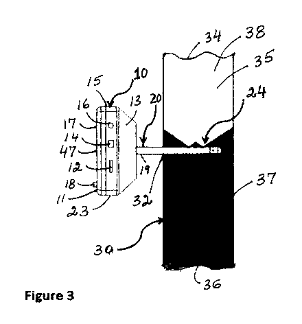
[00251 Figure 3, illustrates a side cut-away view of the borescope
apparatus 3,
showing the probing tube 20, as inserted through a wall 30. When an inspection
or probing
of a wall or ceiling 30, is desired one would .make a .small hole or opening
32, on. .the desired
surface or location on the wall or .ceiling 30, It .is preferred that the hole
or opening 32, is just
slightly lamer than the corresponding cross-sectional area of the probing tube
or unit 20.
Once the hole 3Z, has been made the -probing tube 20, is gently inserted 'into
the hole 32, and
into the cavity 38, that needs to be probed. Once inside the cavity 38, the
light source 25, is
activated or turned ON, and that would result in a lighted area 35, and a dark
area 37. With
the light source25, activated, the ima.ge sensor 27, can now be activated or
turned ON, to
either view the inside of the cavity 38, or to take images 47, for the video
screen 17, or a
6
CA 02906339 2015-09-14
WO 2014/150055 PCT/US2014/022020
video 47, to beshown or displayed on the screen 1'7. As one can -see that the
,upper area or
portion 34, of the cavity 38, is light 35, due to the activation of the light
source 25, while the
lower area or portion. 36, of the cavity 38, is dark 37, and nothing can be
seen. However, the
inventive borescope 23, MI easily be rotated 360 degrees inside the cavity 38,
to clearly see
andlor capture the inside features of the cavity 38, and thus with a rotation,
such as, a 180
degree rotation, the upper portion 34, would become dark 379 while the tower
portion 36,
would fight .up 35, as the light source 2.5, would be pointing towards the
lower portion 36, of
the cavity 38.
[0026] Figure 4, illustrates a perspective view of a borescope apparatus
43, according
to another embodiment of this invention. As shown in Figure 4, the inspection
.camera. 43,
may transmit image or video signals 75, to an external device 53, such as, for
example, a
computer 53, smart-phone 53, a tablet 53, to .name a few, This. transmission
75, of the image
or video 47, onto a. screen 17, may be done in a number of manners, such as,
for example,
streaming of video 47, in a "network" fashion via. µVi-Fi, or it may he done
in an ad-hoc
fashion where the connection is directly between the inspection. camera 43,
.and the devi.ce
53, .without the usage of an existing "network" 75.. For some applications the
transmission
75, could be recorded onto an external device 42, such as, a memory card 42.
[00271 Figure 5, illustrates a perspective view of a borescope
apparatus453, according
toyetanother embodiment of this .invention. An antenna 69, 'could be secured
to the main
body 10, of the borescope 63. The antenna. 69, could be used to wirelessly
transmit 75,
andlor receive 75, information .from other devices or components 53.
[0028j It should be appreciated that die SeTeell .17, of the inspection
scope 23, can be
used to see current or real-time images 47, coming from the probing tube 20,
which would be
the actual viewing of the images 47, captured by the image sensor 27, or it
may be used to
play back the images 47, going to or coming from the -remote device 53, such
as, for
example, as shown in Figure 4.
7
CA 02906339 2015-09-14
WO 2014/150055 PCT/US2014/022020
[00291 The invention may best be further understood by reference to the
ensuing.
detailed description in conjunction -with the drawings in \vhich this new
inventive battery
operated inspection camera 23, 43, 63, allows for the smallest hole 32, for
example, in the
range of about 3 mm, to about 10 min, to be made in an existing wall or
ceiling 30, in order
to ascertain the structure within a wall or a ceiling system 30. ising an
array of light sources
25, such as, at least one LED 25, and at least one image sensor 27, which are
preferably
attached to a hollow solid and rigid tube 20, which allows for easy viewing of
the interior 38,
of the wall 30, on an attached screen Ill, or an external viewing .device 53,
such asõ for
example, a computer 53, a tablet 53, a "smart phone" 53, to name a few. The
rigid nature of
this inspection camera 23, 43, 63, additionally gives a level of wider angle.
of view andlor
visual precision which is not possible with other flexible camera systems or
borescope for
viewing inside, for example, walls or ceilings 30. This type of system is
ideal for general.
building professionals who Want a simple and minimally destructive or
disruptive way to see
inside, for example, walls 30, ceilings. 30, .or any other visually hidden
space or surface 30, in
order to make a proper assessment
[0030] In one embodiment .of the inventive borescope device 23, 43, 63,
there may be
no need for including an LCD screen 17, since the viewing 47, may be done
solely on an.
external de-vice 53, such as, a computer 53, a smart-phone 53, a tablet 53, to
name a few, as
More Clearly shown in Figure 4. Additionally the general shape of the
apparatus 23, 43, 63,
specially the viewing or main body segment 10, may look different as long.as
the rigid tubing
20, is still attached to it, allowing for a set of LEDs 25, and image
sensor(s) 27, to be placed
in such a wa.y as was described earlier to enable the easy viewing of a cavity
38, of the wall
30. Nvith a minimal creation of a hole or opening 32, in an existing wall 30.
[0031] it should be understood that the inventive inspection scope. 23,
43, 63, has. the
main 'control" .nnit 10, and which unit 10, -houses the control logicõ the
video processing
logic and all user interaction MO elements of the scope 23,43, 63õ including
any and all
buttons or switches ..18: If the -inspection camera 23, 43, 63, is intended to
work wirelessly
75, with devices, as more clearly shown in Figure 4, then .the main body 10,
should also
8
CA 02906339 2015-09-14
WO 2014/150055
PCT/US2014/022020
i#1clude the wireless logic and antenna components 69. The functionality oldie
inspection
camera 23, 43, 63, can vary depending on the .implementation, however in one
instance of
this invention 23, 43, 63, there may be video output ports 16, on the main.
body 10, as well as
various "meinory slots" 12, that allow for a removable storage media 42, to be
inserted into
the device 23, 43, 63, for recording of either still images 47, or video
segments 47,
[0032] .As shown in Figure 5, there may be a video out port 1.6, for
connecting .to an.
analog video display, such as, a W, as .well as a digital output port 14,
which may be a USB
14, a. Fire-wire .14, a .1-IDM1 (i1ich -Definition Multimedia interface) 1.4,
or a number of other
"digital" output ports 14, that allow for the transfer of images 47, and video
47, from the
inspection camera 23, 43, 63, to a computer 53, or other computing. device 53,
such as, for
exampleõ a tablet 53, a smart-phones 53, to name a .few. In addition, some -
versions of this
inspection camera 23, 43, 63, may also include. a "memory slot" 12, which will
allow, for
example, for the. recording of still images 47, video segments 47, onto, for
example, a
memory media. 42,
[0033] As this inventive device 23, 43, 63, is portable the main body-
10, will also
house the battery 70, for the unit 23, 43, 63. This battery 70, ma.y be of the
disposable kind,
as well as., of a rechargeable variety, it is
rechargeable, then it may be charged with the
batteries .70õ remaining M the inspection c.amera 23, 43, 63, during .charging
wrhich can be
accomplished with a charging circuitry in the .main body 10, along with a
connector that
provides electrical connection, for example, to a power wall outlet. It should
also be
appreciated that the 'battery 70, or the .rechargeable battery 70, could be
charged via an
electrical connection 12, 1.4, 16, or via a USB power port 12, 14, 16, or DC
power input port
12, 1.4, 16, or by. using an external power supply , to name a few,
[0034] The boreseope or the .optical monitoring system 23, 43, 63, allows
for the
transmission of imageS from an enclosed environment within the interior .of a
sealed wall 30,
or ceiling 30, to an exterior location. As stated earlierthat the cavity -3S,
or .chamber 38, has
walls 30, and an access port 32, or hole 32, .that is created through .the
surface of the wall 30.
9
CA 02906339 2015-09-14
WO 2014/150055 PCT/US2014/022020
The .borescope.system 23,43, 63, .coniprises:ofa. rigid, generally tubular,
elongated, probing
tube 20, that is preferably inside a sealed housing 20. The distal end 24, of
the probe tube
housing 20, preferably has a sealed window 29. For some applications it is
preferred that the
probing tube 20, from the .distal end 24, to the -proximal end 19, which is
secured to the
housing of the main unit 10,, is environmentally or hermetically sealed. it is
preferred that the
interior of the probing tube housing 20, is accessible -through an access port
or bole from the
interior of the housing of the .main unit 10, including access to the
electronics for the
transmission media for transmitting images 47, of the interior of a cavity 38,
that are obtained
through a window 29, from the distal end 24, of the probe housing, 20, along
Nvith the wiring
for the light source 25, that are inside the probe housing 20.
[00351 The insertion tube 20, can be fashioned front a number of
materials, including,
for .example, metals, .aluminum, plastics, stainless steel, composite
materials, to name a few.
One important distinction. for this segment of the inspection camera 23, 43,
63, is that the
diameter or the cross-section of the tube 20, should be in the range of about
3 min to about 5
mm., and it should be small enough .that it can be inserted in a small hole
32, one which
would require minimal cosmetic fixing/patching on the hole 32, after the
inspection of the
cavity 38.
[0036] The crosssectional area for the inventive insertion tube 20, can
be selected
from a group comprising a. triangle,. a square, a rectangle, a circle, an
oval, a polygonal shape,
a cylindrical shape, and :combinations thereof, to name a few,
[0037] The borescope apparatus 23,43, 63, preferably has at least one
transparent
material 29, to environmentally protect the at least one light source 25, and
the at least one
imaging sensor 27. The at least one transparent material 29, could be selected
from a group
comprising glass, quartz, synthetic sapphire, polymeric matedal, composite
material:, and
combinations thereof, to name a .few.
[0038] The diameter or the cross-sectional area of the tube 20,
preferably xvould
CA 02906339 2015-09-14
WO 2014/150055 PCT/US2014/022020
correspond to at insertion hole 32, which is small enough where an operator,
ora general
contra.ctor, or building owner, would be able to fill .with wallijoint
compound:, and a simple
spackling knife or their bare fingers after an inspection, as this is an
important feature of this
new borescope device 23, 43, 63,
[00391 The insertion tube 20, may be connected to the main bod.y section
10; in a
number of manners, which .may include, but not limited to, being connected in
a solid
fashion, with a flexible joint, with a "ball-joint", to name a few, and it may
be removable so
that it can be placed in a travel box or case (not .shown), At the distal or
peripheral end 24, of
the tube 20, will 'be the segment where the LEDs 25, and the image sensor 27,
will be
preferably located, The LEDs 25, and the image. sensor 27, wiIl be configured
onto the
insertion tube 20, in a. manner such that. they will not interfere -with the
insertion o.f .this tube
20, into a typical wall 30, once a small hole 32; or opening 2,..has been
created. Preferably;
the .1,.,F,Ds 25, as well as the image sensor 27, will be encased inside the
hollow rigid tube22,
in such a way to be Water and dust proof. Although in Figure 1B there are 2
LEDs 25,
illustrated, there. may be instances where more than 2 or even one LED 25, may
be used,
depending on the type of LED 25, deployed at the end of the tube 20, or the
distal end 24. in
fact, there may be in.stances where the LEDs 25, will be of various
spectral..wavelerAlts of
light, both visible and non-visible, depending ()lithe application of the
inspection camera 23,
43, 63, The visible and non-visible LED I ights,25õ :may or .may PM be preseot
both at the
same time on the..same device 23, 4-3, 63, depending on the embodiment of the
invention..
[0040] The. connection .may also utilize other \vireless standards and
protocols 75, for
such external viewing devices 53, as appropriate in order to transmit the
required still images
47, and video streams 47, in as close to real-time as .possible. In instances
of this invention
where wireless streaming, 75, of video 47, to an external device 53, is
enabled, there may not
be an LCD 25, or other viewing apparatus or component on the. main body 10, of
the
inspection camera 23, 43., 63, The viewing functionality would then be
performed by the
external viewing device(s) 53. Additionally, since still images 47, and. video
47, will be
streamed to the viewing device 53, the storage of the images 47, and video
clips 47, may also
CA 02906339 2015-09-14
WO 2014/150055 PCT/US2014/022020
be saved on theviewing device 53, for example, a computer 53, a smart-phone
53, a tablet
53, to name a few.
[0041] It should be appreciated that at least one imaging sensor 27,
could be selected
from a group comprising a camera, a video camera, a still camera, an infrared
camera, and
combinations thereof, to name a few.
[00421 For some applications one could also have an LED intensity control
dimming
button or SWitCh 18, which could be used to contrc.,1 the halm intensity of
the light source 25,
or LED 25, while the probe 20, is inside the cavity 38, as desired,
00431 It should be appreciated that the firmware on the microcontroller
monitors all
the functions of the inventive borescope 23, such as, for example, power state
of the battery
70, the push button controls 18, -video quality 47, on the Kreall 17, failure
detection of any
of the components of the borescope 23, to name a few.
[0(441 The firmware on the microcontroller applies image enhancement
methods to
improve the video 47, or image quality 47, by utilizing various methods of
image
processing, such as, for example, color correction, noise reduction,
smoothing, pixel intensity
mapping garnina correction, to name a few.
[0045] The image enhancement can take place automatically by continuously
getting
feedback from camera sensor, arid/or by applying image correction methods,
which are, well
known in the art.
[00461 :Hardware
Input power
1,1. Replaceable battety(s) 70
1.2. Rechargeable .battety(s) 70
1.3. DC input 12, 14, 16
12
CA 02906339 2015-09-14
WO 2014/150055 PCT/US2014/022020
Camera board
2.1.. Types
2.1.1.. Flexible circuit
2.1,2. Rigid-flex
2,2. Components
2.2.1_ Camera Sensor 27., cart be an analog or a digital camera 27, providing,
fOr example,
VGA (640X480 Pixels). Camera sensor 27 can be upgraded to a higher resolution
sensor 27.
2.2.2, Two or more white LEDs 25, for illumination purpose with dimming
capability using
Pulse Width Modulation .(PWM) or analog voltage control
2.2.3. Infrared LED 25
2.2.4, Flexible cable: carries electrical signal and power to the camera
sensor 27
2.2.5. Position and size: The width of the camera board assembly can be as.
small as 2 .mm
and. its length, including the: flexible cable, can be as long as four feet or
'longer. The camera
27, the LEDs 25, can all be in one..row. Similarly, buttons 18, can all be in
one row.
[0047] Main board
3.1. Description: Mainboard is responsible for controlling system using a
microcontroller
unit (Mal) and also it supplies power to different components on .the design.
3.2. The power circuitry on the main board protects the board from invalid
input voltage
such as :reversed polarity circuitry., high yolta.ge and electrostatic
discharge.
33. Electrical interfaces.
3.3,1. The .mainboard has a connector interface to the camera board
3.3_2. Connector LCD
3.3.3_ Programing and debugging interfaces, an be, for example, SP.", 12C,
,ETAG, .L1ART,
several test points, to name a few..
[00481 Display
3.4,1.. The size ofdisplay 47., may 'vary .from about2.5 inches to about 10
inehes. in the
case of wireless video streaming 75, to a remote viewer 53, the display 47,,
on borescope
ma.y not be needed.
13
CA 02906339 2015-09-14
WO 2014/150055 PCT/US2014/022020
[004911 Software
4.1. Initialization: Boots, initializes and programs the camera sensor,
display and push
button on the board
4.2. Nionitoring batter ylevel and System failures and takes required
action repeatedly.
Battery power LED indicator. Indicates the current state of battery(s) by
diming,.
chanaina color and blinkino-
,
.4.4. image enhancement: Enhances image quality by .adhering differeat
methods of image
processing such as color correction, noise cancelation, smoothina, pixel
intensity mapping
and gamina correction,
00501 The tool used in the preset in-vention, nainely, the boresCope.V.,
43, 63, nay
be implemented using one or more computers executing software instructions,
According to
one embodiment of the present invention, .the borescope 23, 43, 63, may
.communicate with
server and Client computer systems 53 that transmit and receive data. over a
computer
network or a -fiber or copper-based 'telecommunications network 75. The steps
of accessing,
downloading, and manipulating the data, as well as other aspects of the
present invention are
implemented by central processing units (CPU) in .the server and client
computers executing
sequences of instructions stored in a MeMary, The 'memory may be a random
access memory
(RAM), read-only memory (R.01A), a persistent store,. such as a mass storage
device, or any
combination of these devkes. Execution of the sequences of instructions causes
the CPU to
perform steps according to embodiments of the present invention,
[00511 The instructions. 'my be loaded into the memory of the server or
.client
computers from a storage device or from one or more other coniputer systems
over a network
connection. Fo.r example:, a client computer may transmit a sequence of
instructions to the.
server computer in response to a. message transmitted to the client over a
network by the
server. As the server l'eeities the instructions over the network connection,
it. stores the
instructions in memory. The server =may store the instructions for later
execution, .or it may
execute the instructions as they arrive over the network connection. In some
eases, the CPU
14
CA 02906339 2015-09-14
WO 2014/150055 PCT/US2014/022020
.may direct] y support the downloaded instructions, In other cases, the
instructions may not be
directly executable 'by the CPU, and may instead be ex.ecuted by an
interpreter that interprets
the instructions.. In other erribodimentsõ hardwired circuitry may be used in
place of, or in.
combination .with, .software instructions to implement the present invention..
Thus tools used
in the present invention are not limited to any specific conibination of
hardware circuitry and
.software, nor to any particular source for the instructions executed by the
server or client
computers. In some instances, the client and server .functionality .may be
implemented on a
single computer platform.
[0052] Thus, the present invention is not limited to the embodiments
described herein
and the constituent elements of the invention can be modified in various
manners without
departing from the spirit and scope of the invention.. Various aspects of the
invention can also
be extracted from any appropriate combination of a plurality of constituent
elements
disclosed in the embodiments. SOIlle constituent elements ma.y be .deleted in
all of the
constituent elements disclosed in the embodiments. The constituent elements
.described in
different embodiments may be combined arbitrarily.
[00531 Still further,. while certain embodiments of the inventions have
been
described, these enibodiments.have been presented by way of example only, and
are not
intended. to lirnit the scope of the inventions. Indeed, the novel methods and
systems
described herein may be embodied in a variety of other forms; furthermore.
VatiVIS
0MiSSionS, SUbStialtiOnS and changes in the form of the methods and systems
described
herein may be made without departing from the spirit of the inventions.
[0054] h should be further understood that throughout the specification
and claims
several tarns have been used and they take the meanings explicitly associated
herein, unless
the context clearly dictates otherwise. For example, the -phrase "in one
embodiment" as used
herein does not neceSsatily refer to the same embodiment, though it may,
.Additionallyõ the
phrase "in another embodiment" as used herein does not necessarily refer to a
different
embodiment, although it may. Thus, various embodiments of the 'invention may
be readily
CA 02906339 2015-09-14
WO 2014/150055 PCT/US2014/022020
combined, without departing from the scope otOirit of the invention.
[0055] While the present invention has been particularly d.escribed in
conjunction
with a specific preferred embodiment, it is evident that many alternatives,
modifications and
variations will be apparent to those skilled in the art. in light of the
forel..!oing description. It
is therefore contemplated that the appended claims will embrace any such
.altematives,
modifications and variations as falling within the -true scope and spirit of
the present
invention.
16