Note : Les descriptions sont présentées dans la langue officielle dans laquelle elles ont été soumises.
CA 02906754 2015-09-30
P4500CA00
Title
Power Converter for a Light Fixture
Field
The invention relates to power converters for powering light fixtures, and in
particular to
power converters for powering light emitting diode light fixtures.
Background
Light fixtures often require power conditioning units to condition the
incoming electrical
power for use by the light fixture. Light emitting diode (LED) light fixtures
often operate
at voltages below that provided through electrical outlets, and at least for
this reason
require power conditioning. When LED light fixtures are installed in confined
spaces, or
in spaces where the power conditioning unit needs to be hidden from view,
installers of
the LED light fixtures can spend considerable time and effort finding a manner
and
space for installing and hiding the power conditioning unit. In addition to
the physical
positioning, the installer must also wire the power conditioning unit to the
electrical
outlet and to the light fixture. This wiring also requires time and effort,
and can expose
the installer to the danger of coming into contact with powered and live
electronics of
the power conditioning unit.
Summary
According to an embodiment of the present invention there is provided a power
converter for a light fixture, the power converter comprising a casing shaped
as an
elongated box divided laterally into an electronics housing and an input
connection
housing. The power converter also comprises electronics received in the
electronics
housing, the electronics for conditioning an input power for powering the
light fixture, the
1
CA 02906754 2015-09-30
P4500CA00
electronics housing permanently enclosing the electronics to restrict access
to the
electronics. The power converter also comprises an output terminal extending
from an
outside surface of the casing, the output terminal in electrical communication
with the
electronics, the output terminal for connecting the power converter to the
light fixture
and one or more other light fixtures. The power converter also comprises a
through-port
connecting the input connection housing and the electronics housing and an
input
terminal extending through the through-port and accessible inside the input
connection
housing, the input terminal in electrical communication with the electronics,
the input
terminal for connecting the power converter to a power source external to the
power
converter and for receiving the input power. The power converter also
comprises a
wiring port in the casing, the wiring port for allowing passage of an end of
an electrical
cable into the input connection housing for connection to the input terminal.
The power
converter also comprises an access opening in the input connection housing for
allowing an installer to access the input terminal and the end of the
electrical cable
inside the input connection housing, for connecting the end of the electrical
cable to the
input terminal. The power converter also comprises a cover for covering the
access
opening and restricting access to the input terminal and the end of the
electrical cable
inside the input connection housing, the cover releasably securable to the
casing.
The output terminal can comprise a push pin connector.
The output terminal can comprise one or more female digital wire sockets.
The power converter can further comprise a further output terminal extending
from the
outside surface of the casing, the further output terminal in electrical
communication
with the electronics, the further output terminal for connecting the power
converter to the
light fixture.
The output terminal can comprise a push pin connector and the further output
terminal
can comprise a female digital wire socket.
2
CA 02906754 2015-09-30
. ,
P4500CA00
The electronics can comprise an AC/DC converter.
The electronics can comprise a 120V to 12V converter.
The electronics can comprise a driver allowing for dimming the light fixture.
The input terminal can comprise a quick connector.
The power converter can further comprise one or more further wiring ports in
the casing,
the one or more further wiring ports for allowing passage of the end of the
electrical
cable into the input connection housing for connection to the input terminal.
The power converter can comprise three wiring ports in the casing.
At least one of the wiring port and the one or more further wiring ports can
comprise a
knockout.
The casing can have a rectangular lateral cross-section having dimensions
selected to
fit through a standard hole-saw cut-out for light fixture installation.
The rectangular lateral cross-section can have dimensions of at least about
1.5 inches
by at least about 1.5 inches.
The electronics housing can have dimensions of about 3 inches by about 1.5
inches by
about 1.5 inches and the input connection housing can have dimensions of about
2.25
inches by about 1.5 inches by about 1.5 inches, yielding a casing of
dimensions of
about 5.25 inches by about 1.5 inches by about 1.5 inches.
A lateral dividing wall can divide the casing into the electronics housing and
the input
connection housing, and the through-port can comprise an aperture in the
lateral
dividing wall, the aperture for allowing passage of wires for connecting the
input terminal
3
CA 02906754 2015-09-30
P4500CA00
to the electronics, the aperture spaced from the access opening to permit
clearance
between the wires and the cover when the cover is covering the access opening.
4
CA 02906754 2015-09-30
P4500CA00
Description of the Drawings
Embodiments of the present invention will now be described, by way of example
only,
with reference to the attached Figures.
Fig. 1 shows a top perspective view of an example embodiment of the power
converter,
depicting a casing of the power converter and a cover detached from the
casing.
Fig. 2 shows a cross-section of the power converter shown in Fig. 1, along
ling 11-11
marked in Fig. 1.
Fig. 3 shows a top perspective view of the power converter shown in Fig. 1,
depicting
the cover in the process of being secured to the casing.
Fig. 4 shows side elevation and top plan views of a digital wire socket.
Fig. 5 shows a top perspective view of a push pin connector.
Detailed Description
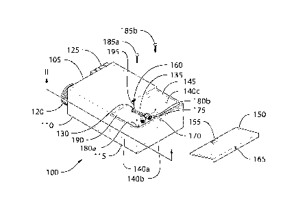
Fig. 1 shows a top perspective view of the power converter 100, which can be
used to
convert and condition electrical power from a power outlet for use by a light
fixture.
Power converter 100 comprises a casing 105, which is shaped as an elongated
box
divided laterally into an electronics housing 110 and an input connection
housing 115.
The lateral division can be along a plane about perpendicular to the longest
side of the
elongated box. In other embodiments, casing 105 can have different shapes and
can be
divided differently into two or more housings.
Electronics 205 (not shown in Fig. 1, but shown schematically in Fig. 2) are
received in
electronics housing 110. Electronics 205 are for conditioning the input power
received
from the electrical outlet, for powering the light fixture. Electronics 205
can include, but
5
CA 02906754 2015-09-30
= P4500CA00
are not limited to, voltage, current, phase, and/or AC/DC converters.
Electronics 205
can convert 120V input power to 12V output power. Electronics 205 can also
convert
AC input power into DC output power. In some embodiments, electronics 205 can
include driver electronics for powering an LED light fixture in addition to
and/or instead
of the power conversion electronics. In some embodiments, the driver
electronics can
allow for dimming the LED light fixture.
Electronics housing 110 can permanently enclose electronics 205 to restrict
access to
electronics 205. This restricted access can protect an installer from
accidentally
touching a part of electronics 205 that is live, particularly parts that are
live with outlet
power at potentially higher and more dangerous voltages. In addition, the
restricted
access can also protect electronics 205 from tampering and/or from being
accidentally
damaged during the installation process. Electronics 205 can be permanently
enclosed
in the sense that after the initial factory installation of electronics 205
into electronics
housing 110, electronics 205 in electronics housing 110 are not readily
accessible by an
installer.
Output terminals 120,125 extend from an outside surface of casing 105. Output
terminals 120,125 are in electrical communication with electronics 205, and
are for
connecting power converter 100 to two or more light fixtures. In other
implementations,
output terminals 120 and/or 125 can be for connecting power converter 100 to
one light
fixture. As shown in Fig. 4, output terminal 120 can comprise a digital wire
socket. The
digital wire socket can be a female digital wire socket, in order to shield
the powered
leads of the socket from being accidentally touched by the installer. In some
embodiments (not shown), power converter 100 can have two or more digital wire
socket output terminals 120.
As shown in Fig. 5, output terminal 125 can comprise a push pin connector.
Push pin
connectors can be assembled side by side, in a modular manner, to expand the
number
of possible connections. As shown in Fig. 1, output terminal 125 comprises a
set of two
side-by-side push pin connectors. In some embodiments, power converter 100 can
6
CA 02906754 2015-09-30
P4500CA00
comprise only one type of output terminal 120 and output terminal 125. In
other words,
power converter 100 can comprise only digital wire socket connectors of output
terminal
120 or only push pin connectors of terminal 125.
In other embodiments, any number and type of output terminals can be used.
When a
modular output terminal is used, for example the push pin connectors of Fig.
5, the
output terminal can be tailored to have the desired number of output
connections.
Power converter 100, through its output terminals 120 and/or 125, can be
configured to
connect to two or more light fixtures in any number of ways, including but not
limited to:
power converter 100 comprising two or more digital wire sockets of output
terminal 120,
each digital wire socket for connecting to a respective light fixture; power
converter 100
comprising two or more sets of push pin connectors of output terminal 125,
each set of
push pin connectors for connecting to a respective light fixture; and power
converter
100 comprising at least one digital wire socket of output terminal 120 and at
least one
set of push pin connectors of output terminal 125, each digital wire socket
and each set
of push pin connectors for connecting to a respective light fixture. Other
numbers and
types of output terminal connectors are also contemplated. The positions of
output
terminals 120,125 on casing 105 are not particularly limited, so long as
output terminals
120,125 are in electrical communication with electronics 205.
A through-port 130 connects input connection housing 115 and electronics
housing 110.
Through-port 130 can comprise an aperture, or other passageway, in a lateral
dividing
wall 190 which divides casing 105 into electronics housing 110 and input
connection
housing 115. The aperture can allow the passage of wires, or other electrical
connection
means, for connecting electronics 205 to an input terminal 135. Input terminal
135
extends through through-port 130 to be accessible to an installer inside input
connection
housing 115. Input terminal 135 is in electrical communication with
electronics 205 and
is for connecting power converter 100 to a power source external to power
converter
100, such as power from an electrical outlet, and for receiving the input
power.
7
CA 02906754 2015-09-30
'
P4500CA00
Power converter 100 can have wiring ports 140a,140b,140c (henceforth denoted
140a-
c) in casing 105. Wiring ports 140a-c are for allowing passage of an end of an
electrical
cable into input connection housing 115 for connection to input terminal 135.
In some
embodiments, wiring ports 140a-c can be knockouts (i.e., partially stamped
openings),
which are knocked out by the installer to open the wiring port 140a-c for the
passage of
the electrical cable. In other embodiments, power converter 100 can have any
number
of wiring ports 140a-c, which can be located anywhere in input connection
housing 115.
In some embodiments, wiring ports 140a-c can be circular with a diameter of
about 7/8
inches (2.22 cm).
Power converter 100 also has an access opening 145 in input connection housing
115
to allow an installer to access input terminal 135 and an end of the
electrical cable that
has been fed into input connection housing 115 through one of wiring ports
140a-c. This
access is to allow the installer to manually connect the end of the electrical
cable to
input terminal 135. Input terminal 135 can terminate in quick connectors 175
to allow the
installer to connect the end of the electrical cable to input terminal 135
quickly and
securely. As shown in Fig. 1, access opening 145 can span one side of input
connection
housing 115. In other embodiments, access opening 145 can be any other shape
or
size, so long as access opening 145 allows the installer access to input
terminal 135
and the end of the electrical cable that has been fed into input connection
housing 115
through one of wiring ports 140a-c.
Power converter 100 can have a cover 150 for covering access opening 145.
Cover 150
can be shaped and sized to completely cover access opening 145. When cover 150
is
covering access opening 145, cover 150 can restrict access to input terminal
135 and
the end of the electrical cable inside input connection housing 115. In some
embodiments, cover 150 can form a slide-in lock with casing 105, using
projection 155
extending from cover 150 and receivable in a corresponding depression 160 in
casing
105. Projection 155 of cover 150 is shown in dotted lines because it is
located on the
side of cover 150 that is obscured from view by cover 150 in Fig. 1.
Projection 155 can
be integrally formed with cover 150, or it can be a separate component
fastened to
8
CA 02906754 2015-09-30
P4500CA00
cover 150. In other embodiments, the projection can extend from casing 105 and
the
depression can be defined in cover 150. Cover 150 can be secured to casing 105
using
the slide-in lock and at least one other releasable fastener, which can
include, but is not
limited to a screw 325 (shown in Fig. 3) passing through cover screw hole 165
and
closure screw hole 170. In yet other embodiments (not shown), there can be no
slide-in
lock and cover 150 can be releasably securable to casing 105 using releasable
fasteners such as screws.
By restricting access to input terminal 135 and the end of the electrical
cable inside
input connection housing 115, cover 150 reduces the chance that anyone would
accidentally touch a live wire inside input connection housing 115. In
addition, restricting
access using cover 150 protects the connection at input terminal 135 from
tampering
and from being accidentally disconnected.
As shown in Fig. 1, aperture of through-port 130 can be spaced from access
opening
145 to allow for clearance 195 between any wires passing through through-port
130 and
cover 150 when cover 150 is covering access opening 145. Clearance 195
provides
sufficient space for the wires passing through through-port 130 so that cover
150 does
not exert a force on the wires that can damage the wires, when cover 150 is
secured to
access opening 145. If such a force is applied, the insulation and or the
conducting core
of the wires can be damaged. If the insulation of the wires is damaged,
shorts, sparks,
fires, or exposed live wires can result. If the conducting core of the wires
is damaged,
power converter 100 may receive no power or unreliable power from its power
source.
In some embodiments, clearance 195 can be about equal to the diameter of the
aperture of through-port 130. In other embodiments, clearance 195 can be about
equal
to twice the diameter of the thickest wire passing through through-port 130.
Power converter 100 can be secured to a substrate using any suitable means,
including
but not limited to screws 185a, 185b passing through installation screw holes
180a,180b
in input connection housing 115.
9
CA 02906754 2015-09-30
P4500CA00
Fig. 2 shows a cross-section of power converter 100, along line 11-11 marked
on Fig. 1.
Fig. 2 depicts casing 105 divided into electronics housing 110 and input
connection
housing 115. Electronics 205 are shown schematically received inside
electronics
housing 110. Through-port 130 in lateral dividing wall 190 connects input
connection
housing 115 to electronics housing 110. Wiring ports 140a-c in casing 105
allow for
passage of an end of an electrical cable into input connection housing 115 for
connection to input terminal 135 (not shown in Fig. 2), which is in turn in
electrical
communication with electronics 205. Output terminals 120,125 extend from
outside of
casing 105 and are in electrical communication with electronics 205, for
connecting
power converter 100 to two or more light fixtures. While power converter 100
can be
capable of being connected to two or more light fixtures through output
terminals 120
and/or 125, it is contemplated that power converter 100 can be connected to
only one
light fixture thereby leaving some connectors of output terminals 120 and/or
125
unconnected.
Fig. 3 shows a top perspective view of power converter 100, with cover 150 in
the
process of being secured to casing 105 to cover access opening 145. Fig. 3
shows
casing 105 divided into electronics housing 110 and input connection housing
115.
Output terminals 120,125 are shown on the outside of casing 105. Projection
155 of
cover 150 is shown in dotted lines because it is located on the side of cover
150 that is
obscured from view by cover 150 in Fig. 3. Projection 155 is shown in the
process of
being received in depression 160 to form a slide-in lock. Screw 325 is shown,
and is
intended for passing through cover screw hole 165 and closure screw hole 170
to
secure cover 150 to casing 105, after the slide-in lock is formed by
projection 155 and
depression 160. Cover screw hole 165 and the corresponding closure screw hole
170
can be located anywhere on the cover 150 and casing 105 respectively, so long
as
screw 325 is able to secure cover 150 to casing 105 by passing through cover
screw
hole 165 and closure screw hole 170. In other embodiments, means other than a
screw
and screw holes can be used in conjunction with a slide-in lock to secure
cover 150 to
casing 105.
CA 02906754 2015-09-30
P4500CA00
Casing 105 can have a rectangular lateral cross-section defined by height 305
and
width 310. Height 305 and width 310 can be selected to fit through a standard
hole-saw
cut-out for light fixture and/or power converter 100 installation. In some
embodiments,
casing 105 has height 305 of about 1.5 inches (3.81 cm) and width 310 of about
2
inches (5.08 cm). In other embodiments, casing 105 has height 305 of about 1.5
inches
(3.81 cm) and width 310 of about 1.5 inches (3.81 cm).
In some embodiments, electronics housing 110 has length 315 of about 3.5
inches
(8.89 cm), width 310 of about 2 inches (5.08 cm), and height 305 of about 1.5
inches
(3.81 cm); and input connection housing 115 has length 320 of about 1.5 inches
(3.81
cm), width 310 of about 2 inches (5.08 cm), and height 305 of about 1.5 inches
(3.81
cm); yielding casing 105 of overall length 330 of about 5 inches (12.70 cm),
width 310 of
about 2 inches (5.08 cm), and height 305 of about 1.5 inches (3.81 cm).
In other embodiments, electronics housing 110 has length 315 of about 3 inches
(7.62
cm), width 310 of about 1.5 inches (3.81 cm), and height 305 of about 1.5
inches (3.81
cm); and input connection housing 115 has length 320 of about 2.25 inches
(5.71 cm),
width 310 of about 1.5 inches (3.81 cm), and height 305 of about 1.5 inches
(3.81 cm);
yielding casing 105 of overall length 330 of about 5.25 inches (13.33 cm),
width 310 of
about 1.5 inches (3.81 cm), and height 305 of about 1.5 inches (3.81 cm).
In some embodiments, the dimensions of input connection housing 115 can be at
least
about 1.5 inches (3.81 cm) by at least about 1.5 inches (3.81 cm) by at least
about 2
inches (5.08 cm) to provide sufficient space to allow an installer to easily
and quickly
connect ends of electrical cables to quick connectors 175 of input terminal
135.
The selection of a suitable dimensions, such as the examples above, can
beneficially
allow for maximizing usable space within casing 105 and for maintaining
sufficient size
to allow convenient manual access by the installer, while still permitting
power converter
100 to be inserted through a standard hole-saw cut-out.
11
CA 02906754 2015-09-30
P4500CA00
Casing 105 can be made of any suitable material including, but not limited to
plastics,
plastic-covered metals, and other insulator-covered metals. Having a cross-
section
dimensioned to fit through a standard hole-saw cut-out allows an installer to
quickly and
easily install and/or hide power converter 100 without the effort of cutting a
polygonal or
non-standard sized hole. The elongated shape of casing 105 allows for housing
all the
components of power converter 100 in a form factor that has a cross-section
small
enough to fit through standard hole-saw cut-outs and a height 305 that is
small enough
to fit in confined spaces for recessed light fixture installation and other
concealed
installations. hole-saw cut-outs, in turn, allows power converter 100 to be
inserted into a
small space (e.g., into or behind a kitchen cabinet, into a wall, etc.) to be
hidden from
view, without the need for special installation tools. Conventional casings
lack such
advantages and are not readily concealed or can only be concealed with the use
of
special tools that installers typically do not carry.
Having electronics 205 permanently enclosed in electronics housing 110 can
protect an
installer for accidentally touching live and/or dangerous parts of electronics
205 and
protects electronics 205 from tampering and being accidentally damaged during
the
installation process. In addition, clearance 195 provides protection to any
wires passing
through through-port 130 from being compressed, chafed, or otherwise damaged
by
opening and closing of the cover 150.
In some embodiments, the slide-in lock can provide a quick and easy means for
guiding
cover 150 into the proper position and alignment for covering access opening
145, and
secures one side of cover 150 to casing 105 without the need for separate
fastening
means or separate fasteners. Reducing the number of required fasteners
facilitates
installation by reducing the time and effort required to secure cover 150 to
casing 105.
In some embodiments, providing both a pig tail wire socket output terminal (as
shown in
Fig. 4) and push pin connector output terminals (as shown in Fig. 5) can allow
for more
versatile connectively of power converter 100 to light fixtures. In addition,
push pin
connectors can be modular, which allows for increasing or decreasing the
number
12
CA 02906754 2015-09-30
P4500CA00
output connections of power converter 100. LED light fixtures can also be
fitted with
push pin connectors, which allow any length of wire to be used to quickly
connect power
converter 100 to an LED light fixture over any desired distance. This adds
flexibility to
and reduces the time required for the installation process. In addition, being
able to
easily use the correct length of wire for connecting the LED light fixture to
a power
converter avoids the limitations of LED light fixtures that have lead wires of
predetermined length; for example, the inability to use the leads to connect
to a power
converter that is further than the length of the lead wire; the inability to
optimally position
the power converter because it would be further from the desired location of
the light
fixture than the length of the lead wire; and having to use an unnecessarily
long lead
wire (and suffering its attendant electrical resistance and resultant voltage
drop) for the
light fixtures that are closer to the power converter than the length of the
lead wire.
Power converter 100 being able to connect, through output terminals 120 and/or
125, to
two or more light fixtures can allow one power converter 100 to power multiple
light
fixtures. In some embodiments, electronics 205 of power converter 100 can
output 12V
which can be used to power many different types of light fixtures, including
LED light
fixtures. Its standard 12V output can allow power converter 100 to power many
different
makes and models of light fixtures made by different manufacturers. In
addition, the use
of widely-used push pin connectors and/or digital wire socket connectors
further allows
power converter 100 to connect to a wide variety of light fixtures from
different
manufacturers. The compatibility of power converter 100 with different makes
and
models of light fixtures combined with its ability to power two or more light
fixtures
reduces the costs and complexity of the installation process by obviating the
need to
purchase and install a specialized power converter for each individual, and
each make
and model of, light fixture.
Moreover, having multiple wiring ports 140a-c on different sides of input
connection
housing 115 can allow input connection housing 115 to provide functionality in
addition
to housing the connection between an electrical cable and input terminal 135.
For
example, referring to Figs. 1 and 2, first an installer can pass a first
electrical cable
13
CA 02906754 2015-09-30
P4500CA00
through a first wiring port, for example wiring port 140a, and make a
connection with
input terminal 135. Then the installer can continue the first electrical cable
and run it
through a second wiring port, different from the first wiring port, for
example wiring port
140b, and out of input connection housing 115. Alternatively, and/or in
addition, the
installer can use a second electrical cable connected to the first electrical
cable and/or
input terminal 135, and run the second electrical cable through the second
wiring port,
or even a third wiring port such as 140c, and out of input connection housing
115. In this
manner, the first electrical cable and the second electrical cable can be
joined together
at an angle, and their connection point can be protected inside input
connection housing
115. In addition, the first electrical cable can be connected to multiple
secondary
electrical cables branching out of input connection housing 115, with each
branch
exiting input connection housing 115 through a different wiring port. The
branching point
can also be protected inside input connection housing 115. In this manner, the
installer
does not need to use a junction box or other connection boxes in addition to
power
converter 100, in order continue and/or branch out the electrical cable beyond
power
converter 100.
The above-described embodiments of the invention are intended to be examples
of the
present invention and alterations and modifications may be effected thereto,
by those of
skill in the art. The scope of the claims should not be limited by the
exemplified
embodiments described above, but should be given the broadest interpretation
consistent with the specification and drawings as a whole.
30
14