Note : Les descriptions sont présentées dans la langue officielle dans laquelle elles ont été soumises.
LIQUID-IMPREGNATED SURFACES WITH ENHANCED DURABILITY
100011
Background
[0002] Embodiments described herein relate generally to devices, systems
and methods for
producing liquid impregnated surfaces with enhanced durability.
[0003] The advent of micro/nano-engineered surfaces in the last decade has
opened up new
techniques for enhancing a wide variety of physical phenomena in thermofluids
sciences. For
example, the use of micro/nano surface textures has provided non-wetting
surfaces capable of
achieving less viscous drag, reduced adhesion to ice and other materials, self-
cleaning, and water
repellency. These improvements result generally from diminished contact (i.e.,
less wetting)
between the solid surfaces and adjacent liquids.
[0004] One type of non-wetting surface of interest is a super hydrophobic
surface. In general,
a super hydrophobic surface includes micro/nano-scale roughness on an
intrinsically hydrophobic
surface, such as a hydrophobic coating. Super hydrophobic surfaces resist
contact with water by
virtue of an air-water interface within the micro/nano surface textures that
allow for a higher
proportion of the surface area beneath the droplet to be air.
[0005] One of the drawbacks of existing non-wetting surfaces (e.g., super
hydrophobic, super
oleophobic, and super metallophobic surfaces) is that they are susceptible to
impalement, which
destroys the non-wetting capabilities of the surface. Impalement occurs when
an impinging liquid
(e.g., a liquid droplet or liquid stream) displaces the air entrained within
the surface textures.
Previous efforts to prevent impalement have focused on reducing surface
texture dimensions from
micro-scale to nano-scale.
[0006] Another drawback with existing non-wetting surfaces is that they are
susceptible to ice
formation and adhesion. For example, when frost forms on existing super
hydrophobic
1
CA 2906827 2020-03-13
CA 02906827 2015-09-14
WO 2014/145414 PCT/US2014/030179
surfaces, the surfaces become hydrophilic. Under freezing conditions, water
droplets can
stick to the surface, and ice may accumulate. Removal of the ice can be
difficult because the
ice may interlock with the textures of the surface. Similarly, when these
surfaces are exposed
to solutions saturated with salts, for example as in desalination or oil and
gas applications,
scale builds on surfaces and results in loss of' functionality. Similar
limitations of existing
non-wetting surfaces include problems with hydrate formation, and formation of
other
organic or inorganic deposits on the surfaces.
100071 Thus,
there is a need for non-wetting surfaces that are more robust. In particular,
there is a need for non-wetting surfaces that are more durable and can
maintain super
hydrophobicity even after repeated use.
Summary
100081
Embodiments described herein relate generally to devices, systems and methods
for producing liquid impregnated surfaces with enhanced durability. In some
embodiments, a
liquid-impregnated surface includes a first surface having a first roll off
angle. A plurality of
solid features are disposed on the first surface, such that a plurality of
interstitial regions are
defined between the plurality of solid features. An impregnating liquid is
disposed in the
interstitial regions and the interstitial regions are dimension and configured
such that that the
in liquid is retained in the interstitial regions by capillary forces.
The
impregnating liquid disposed in the interstitial regions defines a second
surface having a
second roll off angle less than the .first roll off angle. The apparatus
includes a liquid delivery
mechanism configured to transfer the impregnating liquid to the interstitial
regions.
Brief Description of the Drawings
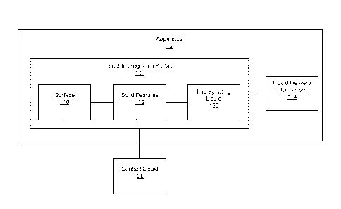
100091 FIG. 1
is a schematic illustration of an apparatus that includes a liquid-
impregnated surface and a liquid delivery mechanism, according to an
embodiment.
[00101 FIG. 2A
shows a schematic illustration of a droplet of a liquid on a surface
showing a critical contact angle. FIG. 2B shows the advancing and receding
contact angles
of the liquid droplet when the surface is inclined.
[00111 FIG. 3
is a schematic illustration of a surface with semi solid features, according
to an embodiment.
2
CA 02906827 2015-09-14
WO 2014/145414 PCT/US2014/030179
[0012] FIG. 4 is a schematic illustration of a surface with hierarchical
semi solid features,
according to an embodiment.
[00131 FIG. 5 is a schematic illustration of the surface of FIG. 3
partially impregnated
with an impregnating liquid.
[00141 FIG. 6 is an enlarged view of the region shown by arrow A of the
liquid
impregnated surface of FIG. 3.
[00151 FIG. 7a-b is a schematic diagram of a liquid droplet placed on a
liquid
impregnated surface, according to an embodiment. FIG. 7c-d show photographs of
a water
droplet on a liquid impregnated surface. FIGS. 7e-f are laser confocal
microscopy images
and FIGS. 7i-j are ESEM images of a liquid impregnated surface according to an
embodiment.
[00161 FIG. 8 show schematic illustrations and corresponding equations of
various
thermodynamic states of a liquid-impregnated surface.
[00171 FIG. 9 shows a thermodynamic regime map of various states of a
liquid-
impregnated surface.
[0018j FIG. 10a shows a plot of measured roll off angles of different
liquid impregnated
surfaces. FIG. 10b shows SEM images of a liquid impregnated surface with solid
features
and FIG. 10c shows SEM images of liquid impregnated surfaces with hierarchical
solid
features. FIG. 10d shows a non-dimensional plot of scaled gravitational force
at the instant of
roll-off as a function of the relevant pinning force of the liquid impregnated
surfaces of FIG.
10a.
[0019] FIG. 11a shows measured velocities of water droplets as a fimcfion
of substrate tilt
angle. FIG. 11b shows a schematic of a water droplet moving on a liquid-
impregnated
surface showing the various parameters considered in a scaling model,
described herein.
FIG. 11c shows trajectories of coffee particles entrained in the water droplet
rolling on the
liquid-impregnated surface. FIG. I Id shows a non-dimensional plot obtained
from the model
described herein.
(00201 FIG. 12 shows a liquid-impregnated surface according to an
embodiment.
3
CA 02906827 2015-09-14
WO 2014/145414 PCT/US2014/030179
[0021] FIG. 13A-B shows a liquid-impregnated surface fluidically coupled to
a reservoir,
according to an embodiment.
[0022] FIG. 14 shows a liquid-impregnated surface included in a container
that includes a
multi-phase liquid, according to an embodiment.
[0023] FIG. 15A shows a side-cross section view of an apparatus that
includes a pipe
having a liquid-impregnated surface and a sheath disposed around the pipe such
that a
reservoir for containing a volume of replenishing impregnating liquid is
formed between the
pipe and the sheath. FIG. 15B shows a front cross-section view of the
apparatus taken along
the line 15B-15B shown in FIG. 15A..
[0024] FIG. 16 shows a side cross-section view of an apparatus that
includes a pipe
having a liquid-impregnated surface and a tee disposed around a through hole
portion of the
pipe such that a reservoir for containing a volume of replenishing
impregnating liquid is
formed between the pipe and the tee.
[00251 FIG. 17 shows a liquid delivery mechanism that includes sponge,
according to an
embodiment.
[0026] FIG. 18A shows a container that includes an impregnating liquid
reservoir and a
deformable surface in a first configuration, according to an embodiment. FIG.
18B shows the
container of FIG. 18A in a second configuration.
[0027] FIG. 19 shows a flow chart illustrating a method for forming a
liquid-impregnated
surface, according to an embodiment
100281 FIG. 20A. shows an SEM image of a PET surface spray coated with
beeswax
particles. FIG. 20B shows an enlarged SEM image of a portion of the surface
shown in FIG.
20A.,
[0029] FIG. 21A shows an SEM image of an aluminum surface etched in an acid
to form
hierarchical solid features. FIG. 21B shows an enlarged SEM: image of a
portion of the
aluminum surface shown in FIG. 21A showing the hierarchical nanofeatures
formed on the
surface.
[00301 FIG. 22A shows an SEM image of a stainless steel surface which was
sand blasted
4
CA 02906827 2015-09-14
WO 2014/145414 PCT/US2014/030179
to form solid features. FIG. 22B shows an enlarged SEM image of a portion of
the aluminum
surface shown in FIG. 22A.
[00311 FIG. 23a shows condensation of water droplets on a first liquid-
impregnated
surface that includes a 100 cSt silicon oil as an impregnating liquid. FIG.
23b shows an
enlarged view of a portion of the first liquid-impregnated surface. FIG. 23c
shows
condensation of water droplets on a second liquid-impregnated surface that
includes a 10 cSt
silicone oil as the impregnating liquid.
[00321 FIGS. 24 and 25 show an optical image of an exemplary apparatus that
includes a
pipe having a liquid-impregnated surface and a tee coupled to a through hole
portion of the
pipe such that a reservoir for housing replenishing impregnating liquid is
formed between the
pipe and the tee.
100331 FIG. 26 shows a plot of the flow rate of a contact liquid through
the pipe shown in
FIGS. 24 and 25, compared with the flow rates of the contact liquid through a
second pipe
that does not include a liquid-impregnated surface or a reservoir, a third
pipe that includes a
liquid-impregnated surface but not a reservoir, and a fourth pipe that does
not include a liquid
impregnated surface but includes a reservoir of impregnating liquid.
Detailed Description
[00341 Some known surfaces with designed chemistry and roughness, possess
substantial
non-wetting (hydrophobic) properties which can be extremely useful in a wide
variety of
commercial and technological applications. Som.e hydrophobic surfaces are
inspired by
nature, such as for example, the lotus plant which includes air pockets
trapped within the
micro or nano-textures of the surface, increasing the contact angle of a
contact liquid (e.g.,
water or any other aqueous liquid) disposed on the hydrophobic surface. As
long as these air
pockets are stable, the surface continues to exhibit hydrophobic behavior.
Such known
hydrophobic surfaces that include air pockets, however, present certain
limitations including,
for example: i) the air pockets can be collapsed by external wetting
pressures, ii) the air
pockets can diffuse away into the surrounding liquid, iii) the surface can
lose robustness upon
damage to the texture, iv) the air pockets may be displaced by low surface
tension liquids
unless special texture design is implemented, and v) condensation or frost
nuclei, which can
CA 02906827 2015-09-14
WO 2014/145414 PCT/US2014/030179
form at the nanoscale throughout the texture, can completely transform the
wetting properties
and render the textured surface highly wetting.
[00351 Non-wetting surfaces can also be formed by disposing a liquid-
impregnated
surface on a substrate. Such liquid-impregnated surfaces can be nonwetting to
any liquid, i.e.
omniphobic (e.g. super hydrophobic, super oleophobic, or super metallophobic),
can be
configured to resist ice and frost formation, and can be highly durable.
Liquid-impregnated
surfaces can be disposed on any substrate, for example, on the inner surface
of pipes,
containers, or vessels, and can be configured to present a non-wetting surface
to a wide
variety of products, for example, food products, pharmaceuticals, over-the-
counter drugs,
nu.traceuticals, health and beauty products, industrial greases, inks,
bitumen, cement,
adhesives, hazardous waste, consumer products, or any other product, such that
the product
can be evacuated, detached, or otherwise displaced with substantial ease on
the liquid-
impregnated surface.
[00361 Liquid-impregnated surfaces described herein, include impregnating
liquids that
are impregnated into a rough surface that includes a matrix of solid features
defining
intersti.tial.s regions, such that the interstitial regions include pockets of
impregnating liquid.
The impregnating liquid is configured to wet the solid surface preferentially
and adhere to the
micro-nano textured surface with strong capillary forces, such that the
contact liquid has an
extremely high advancing contact angle and an extremely low roll off angle
(e.g., a roll off
angle of about 1 degree and a contact angle of greater than about 100
degrees). This enables
the contact liquid to displace with substantial ease on the liquid-impregnated
surface.
Therefore, the liquid-impregnated surfaces described herein, provide certain
significant
advantages over conventional super hydrophobic surfaces including: i) the
liquid-
impregnated surfaces creates a low hysteresis for the product, ii) such liquid-
impregnated
surfaces can include self cleaning properties, iii) can withstand high drop
impact pressure
(i.e., are wear resistant), iv) can self heal by capillary wicking upon
damage, v) can repel a
variety of contact liquids, such as semisolids, slurries, mixtures and/or non-
Newtonian. fluids,
for example, water, edible liquids or formulations (e.g., ketchup, catsup,
mustard,
mayonnaise, syrup, honey, jelly, etc.), environmental fluids (e.g., sewage,
rain water), bodily
fluids (e.g., urine, blood, stool), or any other fluid (e.g. hair gel,
toothpaste), vi) can reduce
ice formation, vii) enhance condensation, viii) allow mold release, ix)
prevent corrosion, x.)
reduce ice or gas hydrate adhesion, xi) prevent scaling from salt or mineral
deposits, xii)
6
reduce biofouling, and xiii) enhance condensation. Examples of liquid-
impregnated surfaces,
methods of making liquid-impregnated surfaces and applications thereof, are
described in U.S.
Patent No. 8,574,704, entitled "Liquid-Impregnated Surfaces, Methods of
Making, and Devices
Incorporating the Same," filed August 16,2012. Examples of materials used for
forming the solid
features on the surface, impregnating liquids, and applications involving
edible contact liquids, are
described in U.S. Patent No. 8,535,779, entitled "Self-Lubricating Surfaces
for Food Packaging
and Food Processing Equipment," issued September 17, 2013. Examples of non-
toxic liquid-
impregnated surfaces are described in U.S. Provisional Application No.
61/878,481, (the '481
application) entitled "Non-toxic Liquid-Impregnated Surfaces", filed September
16, 2013.
[0037] . In some cases, the impregnating liquid included in the liquid-
impregnated surface can
get displaced from within the interstitial regions defined by the solid
features included in the liquid-
impregnated surface. For example, a shear force of a bulk fluid (e.g., a non-
Newtonian fluid)
flowing over the liquid-impregnated surface can shear the impregnating liquid
from the liquid-
impregnated surface. This can lead to gradual loss of the impregnating liquid
and can lead to a
decrease in the non-wetting performance of the liquid-impregnated surface.
[0038]
Embodiments of the liquid-impregnated surface described herein include
articles,
systems and methods configured to provide a replenishing supply of the
impregnating liquid to the
liquid-impregnated surface. This can ensure that any volume of the
impregnating liquid lost from
the liquid-impregnated surface is replaced with fresh impregnating liquid such
that the non-wetting
properties of the liquid-impregnated surface are maintained. Thus, the liquid-
impregnated surfaces
described herein can have enhanced durability and long life-time. The liquid-
impregnated surfaces
described herein can be used in systems where a continuous flow or repeated
flow of a liquid is
desired over extended periods of times, for example, process tubes, pipes,
conduits, vessels, multi-
use containers, or any other article or container.
100391 In
some embodiments, a liquid-impregnated surface includes a first surface having
a
first roll off angle. A plurality of solid features are disposed on the first
surface, such that
interstitial regions are defined between the plurality of solid features. An
impregnating liquid
7
CA 2906827 2020-03-13
CA 02906827 2015-09-14
WO 2014/145414 PCMJS2014/030179
is disposed in the interstitial regions. The interstitial regions are
dimensioned and configured
such that the impregnating liquid is retained in the interstitial regions
through capillarity. The
impregnating liquid disposed in the interstitial regions defines a second
surface which has a
second roll off angle less than the first roll off angle. The apparatus also
includes a liquid
delivery mechanism configured to transfer the impregnating liquid to the
interstitial regions
10040! In some embodiments, an apparatus having a liquid-impregnated
surface can
include a first substrate having a first surface, a second surface and a
plurality of pores, such
that the pores extend from the first surface to the second surface. The
apparatus also includes
a second substrate which is spaced apart from the second surface, such that
the second
surface of the first substrate and the second substrate define an interior
region. A. plurality of
solid features are disposed on the first surface of the first substrate, such
that the plurality of
solid features define interstitial regions between the plurality of solid
features. An
impregnating liquid is disposed in the interstitial regions. The interstitial
regions are
dimensioned and configured such that they remain impregnated by the
impregnated liquid
through capillarity. A supply of impregnating liquid is disposed in the
interior region defined
by the first surface of the first substrate and the second substrate, and is
fluidically coupled to
the interstitial regions by one or more pores such that the impregnating
liquid can flow from
the interior region to the interstitial regions the pore or pores.
100411 In some embodiments, an apparatus can include a container having an
interior-
surface and an exterior surface such that the interior and the exterior
surface define an interior
region configured to contain a liquid. A plurality of solid features are
disposed on the interior
surface of the container such that the plurality of solid features define
interstitial regions
between the plurality of solid features. An impregnating liquid is disposed in
the interstitial
regions and the interstitial regions are dimensioned and configured such that
capillary forces
retain the impregnating liquid in the interstitial regions. A. liquid mixture
is disposed in the
interior region and is in contact with the impregnating liquid impregnating
the interstitial
regions. The liquid mixture includes the impregnating liquid therein such that
the liquid
mixture can supply the impregnating liquid to the interstitial regions. In
some embodiments,
the liquid mixture is a multiphase liquid. In some embodiments, the liquid
mixture is
formulated such that when the temperature of the apparatus increases from a
first temperature
to a second temperature, the liquid mixture becomes unstable and separates
into two distinct
bulk phases. In some embodiments, the interior surface can have a first roll
off angle, while
8
CA 02906827 2015-09-14
WO 2014/145414 PCT/US2014/030179
the impregnating liquid disposed in the interstitial regions defines a contact
surface which has
a second roll off angle less than the first roll off angle. In some
embodiments, the liquid
mixture is formulated to supply impregnating liquid to the interstitial
regions to maintain the
second roll off angle less than the first roll off angle.
[00421 In some embodiments, a method of forming a liquid impregnated
surface includes
disposing a plurality of solid features on a first surface having a first roll
off angle. An
impregnating liquid is applied to the first surface such that the impregnating
liquid fills the
interstitial regions between the plurality of solid features and forms a
second surface having a
second roll off angle less than the first roll off angle. The method further
includes reapplying
the impregnating liquid to maintain the second roll off angle of the second
surface less than
the first roll off angle. In some embodiments, the impregnating liquid can be
applied from a
multi-phase liquid in contact with the impregnating liquid disposed in the
interstitial regions.
In some embodiments, the impregnating liquid is reapplied from a liquid
delivery mechanism
in fluid communication with the interstitial regions. In some embodiments, the
liquid
delivery mechanism is in fluid communication with the interstitial regions by
at least one of
the following: capillary action, pressure differential, temperature
differential, concentration
and/or surface tension gradients.
[00431 As used herein, the term "about" and "approximately" generally mean
plus or
minus 10% of the value stated, for example about 250 p.m would include 225 p.m
to 275 p.m,
about 1,000 p.m would include 900 p.m to 1,100 p.m.
100441 As used herein, the term "contact liquid", "bulk material, and
"product" are used
interchangeably to refer to a solid or liquid that flows, for example a non-
Newtonian fluid, a
Bingham fluid, a high viscosity fluids, or a thixotropic fluid and is contact
with a liquid-
impregnated surface, unless otherwise stated.
100451 FIG. 1 illustrates a schematic block diagram. of an apparatus 10
that includes a
liquid-impregnated surface 100 and a liquid delivery mechanism 114. The liquid-
impregnated surface includes a surface 110, a plurality of solid features 112
and an
impregnating liquid 120. The impregnating liquid 120 is impregnated into the
interstitial
regions defined by the plurality of solid features 112. The liquid-impregnated
surface can be
in contact with a contact liquid CL, such that the contact liquid CL can
easily move over the
liquid-impregnated surface 100. The liquid delivery mechanism 114 is
configured to transfer
9
CA 02906827 2015-09-14
WO 2014/145414 PCT/US2014/030179
the impregnating liquid to the interstitial regions, as described herein.
(0046) The
surface 110 can be any surface, which is configured to contact a contact
liquid. For example, in some embodiments, the surface 110 can be an inner
surface of a
container and can have a first roll off angle, for example, a roll off angle
of a contact liquid
CL (for example, a consumer product, laundry detergent, cough syrup, an edible
contact
liquid, an industrial liquid, or any other contact liquid described herein).
The surface 110 can
be a flat surface, for example an inner surface of a prismatic container,
silicon wafer, glass
wafer, a table top, a wall, a wind shield, a ski goggle screen, or a contoured
surface, for
example, a container (e.g. a beverage container), a propeller, a pipe, an
inner surface, of a
circular, oblong, rectangular, elliptical, oval or otherwise contoured
container.
100471 In some
embodiments, the surface 110 can be an inner surface of a container. The
container can include any suitable container such as, for example, tubes,
bottles, vials, flasks,
molds, jars, tubs, cups, caps, glasses, pitchers, barrels, bins, totes, tanks,
kegs, tubs, syringes,
tins, pouches, lined boxes, hoses, cylinders, and cans. in such embodiment,
the container can
be constructed in almost any desirable shape. The container can be constructed
of rigid or
flexible materials. Foil-lined or polymer-lined cardboard or paper boxes can
also be used to
form the container. In some embodiments, the surface 110 can include a surface
of hoses,
piping, conduit, nozzles, syringe needles, dispensing tips, lids, pumps, and
other surfaces for
containing, transporting, or dispensing the contact liquid CL The surface 110
can be formed
from any suitable material including, for example plastic, glass, metal,
alloys, ceramics,
coated fibers, any other material, or combinations thereof. Suitable surfaces
can include, for
example, polystyrene, nylon, polypropylene, wax, fluorinated wax, natural
waxes, siliconyl
waxes, polyethylene terephthalate, polypropylene, poly propylene carbonate,
poly imide,
polyethylene, polyurethane, graphene,
polysulphone, polyethersul fone,
polytetrafluoroethylene (PTFE), tetrafluoroethylene (TFE), fluorinated
ethyl.en.epropyl.ene
copolymer (FEP), polyvinylidene fluoride (PVDF),
perfluoroalkoxytetrafluoroethylene
copolymer (PFA), perfluoromethyl vinylether copolymer (:MFA),
ethylenechlorotrifluoroethylene copolymer (ECTFE), ethylene-
tetrafluoroethylene copolymer
(ETFE), perfluoropolyether(PFPE), polychlorotetrafluoroethylene (PCTFE),
polyvinyl
alcohol (PVA), polyvinyl acetate (PVAc), polyethyleneglycol (PEG),
Polyvinylpyrrolidone
(PVP), Polylactic acid (PIA), A.crylonitril.e butadiene styrene (A.BS),
Tecnoflon cellulose
acetate, poly(acrylic acid), poly(propylene oxide), Dsorbitol, erythritol,
xylitol, lactitol,
CA 02906827 2015-09-14
WO 2014/145414 PCT/US2014/030179
maltitol, mannitol, and polycarbonate.
[0048] A plurality of solid features 112 are disposed on the surface 110,
such that the
plurality of solid features 112 define interstitial regions between the
plurality of solid features
112. In some embodiments, the solid features 112 can be posts, spheres,
micro/nano needles,
nanograss, pores, cavities, interconnected pores, inter connected cavities,
any other random
geometry that provides a micro and/or nano surface roughness. In some
embodiments, the
height of the solid features can be about 10 gm, 20 gm, 30 gm, 40 p,m, 50 gm,
60 gm, 70
gm, 80 gm, 90 gm, 100 gm, 200 gm., 300 pm, 400 gm, 500 gm, 600 gm, 700 gm, 800
gm,
900 JIM, up to about 1 mm, inclusive of all ranges therebetween, or any other
suitable height
for receiving the impregnating liquid 120. In some embodiments, the height of
the solids
features 112 can be less than about 1 gm. For example, in some embodiments,
the solid
features 112 can have a height of about 1 nm, 5 nm, 10 nm, 20 nm, 30 urn 40
nm, 50 nm, 100
nm, 200 nm, 300 nm, 400 rim, 500 rim, 600 rim, 700 nm, 800 nm, 900 nm, or
about 1,000 nm,
inclusive of all ranges therebetween. Furthermore, the height of solid
features 112 can be, for
example, substantially uniform. In some embodiments, the solid features can
have a wenzel
roughness "r" greater than about 1.01, 1.05, 1.1, 1.2, 1.3, 1.4, 1.5, 1.6,
1.7, 1.8, 1.9, 2.0, 2.5,
3, 5, or about 10. In some embodiments, the solid features 112 can have an
interstitial
spacing, for example, in the range of about 1 gm to about 100 gm, or about 1
nm to about 1
Jim. In some embodiments, the textured surface 110 can have hierarchical
features, for
example, micro-scale features that further include nano-scale features
thereupon. In some
embodiments, the surface 110 can be isotropic. In some embodiments, the
surface 110 can be
anisotropic.
[00491 The solid features 112 can be disposed on the surface 110 using any
suitable
process. For example, in some embodiments, a top down fabrication process can
be used to
form the solid features 112 on the surface 110. For example, micro and/or nano-
lithography
(e.g., photolithography, SU-8 masks, nano imprinting, hard masking, shadow
photolithography, etc.) can be used to define the solid features 112 on the
surface 110, for
example, silicon, glass, chromium, gold, PDMS, parylene, or any other suitable
surface. In
som.e embodiments, the micro and/or nano patterns can be used as the features
of the solid
features 112. In some embodiments, the micro and/or nano-patterns can be used
as masks for
further etching of the surface 110, for example, wet chemical etching (e.g.,
using buffered
hydrofluoric acid, gold etchant, chromium etchant), or dry etching (e.g.,
reactive ion etching,
11
CA 02906827 2015-09-14
WO 2014/145414 PCT/US2014/030179
deep reactive ion etching, SF6 etching, electron beam lithography, plasma beam
lithography,
etc.). In some embodiments, the solid features 112 can be grown in-situ on the
surface, for
example, using atomic layer deposition (ALD), sputtering, e-beam deposition,
chemical
vapor deposition, plasma enhanced chemical vapor deposition, and the likes.
[00501 In some embodiments, the solid features 112 can be disposed on the
inner surface
of a container (e.g., any of the containers described herein) or be integral
to the surface itself
(e.g., the textures of a polycarbonate bottle may be made of polycarbonate).
In some
embodiments, the solid features 112 may be formed of a collection or coating
of particles
including, but not limited to insoluble fibers (e.g., purified wood cellulose,
micro-crystalline
cellulose, and/or oat bran fiber), wax (e.g., camauba wax, Japan wax, beeswax,
candelilla
wax, rice bran wax), shellac, fluorinated waxes, siliconyl waxes, other
polysaccharides,
fructo-oligosaccharides, metal oxides, montan wax, lignite and peat,
ozokerite, ceresins,
bitumens, petrolatuns, paraffins, microcrystalline wax, lanolin, esters of
metal or alkali, flour
of coconut, almond, potato, wheat, pulp, zein, dextrin, cellulose ethers
(e.g., Hydroxyethyl
cellulose, Hydroxypropyl cellulose (UPC), Hydroxyethyl methyl cellulose,
Hydroxypropyl
methyl cellulose (HPMC), Ethyl hydroxyethyl cellulose), ferric oxide, ferrous
oxide, silicas,
clay minerals, bentonite, palygorskite, kaolinitc, vermiculite, apatite,
graphite, molybdenum
disulfide, mica, boron nitride, sodium formate, sodium olcate, sodium
palmitate, sodium
sulfate, sodium alginate, agar, gelatin, pectin, gluten, starch alginate,
carrageenan, whey
and/or any other edible solid particles described herein or any combination
thereof.
100511 In some embodiments, surface energy of the surface 110 and/or the
solid features
112 can be modified, for example, to enhance the adhesion of the solid
features 112 to the
surface 110 or to enhance the adhesion of the impregnating liquid 120 to the
solid features
112 and/or the surface 110. Such surface modification processes can include,
for example,
sputter coating, silane treatment, fluoro-polymer treatment, anodization,
passivation,
chemical vapor deposition, physical vapor deposition, oxygen plasma treatment,
electric arc
treatment, thermal treatment, any other suitable surface chemistry
modification process or
combination thereof.
[00521 In some embodiments, the solid features 112 can be disposed by
exposing the
surface 110 (e.g., polycarbonate) to a solvent (e.g., acetone). For example,
the solvent may
impart texture by inducing crystallization (e.g., polycarbonate may
recrystallize when
exposed to acetone). In some embodiments, the solid features 112 can be
disposed by
12
CA 02906827 2015-09-14
WO 2014/145414 PCT/US2014/030179
dissolving, etching, melting, reacting, treating, or spraying on a foam or
aerated solution,
exposing the surface to electromagnetic waves such as, for example ultraviolet
(UV) light or
microwaves, or evaporating away a portion of a surface, leaving a textured,
porous, and/or
rough surface behind that includes a plurality of the solid features 112. In
some
embodiments, the solid features 112 can be defined by mechanical roughening
(e.g., tumbling
with an abrasive, sandblasting, sanding), spray-coating or polymer spinning,
plasma spraying,
thermal spraying, deposition of particles from. solution (e.g., layer-by-layer
deposition,
evaporating away liquid from a liquid/particle suspension contacting the
surface), and/or
extrusion or blow-molding of a foam, or foam-forming material (for example a
poly-urethan.e
foam). In some embodiments, the solid features 112 can also be formed by
deposition of a
polymer from. a solution (e.g., the polymer forms a rough, porous, or textured
surface);
extrusion or blow-molding of a material that expands upon cooling, leaving a
wrinkled
surface; and application of a layer of a material onto a surface that is under
tension or
compression, and subsequently relaxing the tension or compression of surface
beneath,
resulting in a textured surface.
[00531 In some embodiments, the solid features 112 can be formed by
disposing a
material, for example, a porous media on the surface capable of forming a
layer of the
material on the surface that includes pores of different sizes, and/or self-
assembles on the
surface 110. For example, in some embodiments, the solid features 112 are
disposed through
non-solvent induced phase separation of a polymer, resulting in a sponge-like
porous
structure. This can include, for example, a solution of polysulfone,
poly(vinylpyrrolidone),
and DMAc may be cast onto a substrate and then immersed in a bath of water.
Upon
immersion in water, the solvent and non-solvent exchange, and the polysulfone
precipitates
and hardens. The material can be disposed on the surface 110 by any suitable
method, for
example, spray coating, immersion (dip) coating, vapor deposition, pouring
and/or any other
suitable method to form the textured surface 110.
[00541 The solid features 112 can include micro-scale features such as, for
example posts,
pillars, spheres, nano-needles, pores, cavities, interconnected pores,
grooves, ridges, spikes,
peaks, interconnected cavities, bumps, mounds, particles, particle
agglomerations, or any
other random geometry that provides a micro and/or nano surface roughness. In
some
embodiments, the solid features 112 can include particles that have micro-
scal.e or nano-scale
dimensions which can be randomly or uniformly dispersed on a surface.
Characteristic
13
CA 02906827 2015-09-14
WO 2014/145414 PCT/US2014/030179
spacing between the solid features 112 can be about 1 mm, about 900 gm , about
800 pm ,
about 700 gm, about 600 pm, about 500 pm, about 400, pm, about 300 pm, about
200 pm,
about 100 pm, about 90 p.m, about 80 pm, about 70 pmõ about 60 pm, about 50
pm, about 40
gm, about 30 pm, about 20 pm, about 10 pm, about 5 pm, 1 p.m, or 100 nm, about
90 nm,
about 80 nm, about 70 nm, about 60 nm, about 50 nm, about 40 nm, about 30 nm,
about 20
rim, about 10 nm, or about 1 rim. In some embodiments, characteristic spacing
between the
solid features 112 can be in the range of about 100 p.m to about 100 nm, about
30 pm. to
about 1 pm, or about 10 p.m to about 1 p.m. In some embodiments,
characteristic spacing
between solid features 112 can. be in the range of about 100 p.m to about 80
pm, about 80 fLM
to about 50 pm, about 50 p.m to about 30 p.m, about 30 pm to about 10 pm,
about 10 fLM to
about 1 pm, about 1 pm to about 90 nm, about 90 rim to about 70 nm, about 70
nm to about
50 nm, about 50 nm to about 30 nm, about 30 nm, to about lOnm, or about 10 nm
to about 1
rim, inclusive of all ranges therebetween.
[0055) In some embodiments, the solid features 112, for example solid
particles can have
an average dimension of about 200 pm, about .100 pm, about 90 um, about 80
fLM, about 70
pm, about 60 gm, about 50 gm, about 40 pm, about 30 pm, about 20 pm, about 10
pm, about
gm, 1 gm, about 100 nm, about 90 nm, about 80 nm, about 70 nm, about 60 nm,
about 50
nm, about 40 nm, about 30 rim, about 20 nm, about 10 nm, or about 1 nm. In
some
embodiments, the average dimension of the solid features 112 can be in the
range of about
100 p.m to about 100 nm, about 30 pm to about 10 fLM, or about 20 gm to about
1 pm. In
some embodiments, the average dimension of the solid feature 112 can be in the
range of
about 100 pm to about 80 gm, about 80 gm to about 50 pm, about 50 pm to about
30 pm, or
about 30 p.m to about 10 um, or 10 pm to about 1 pm, about 1 p.m to about 90
nm, about 90
nm to about 70 nm, about 70 nm to about 50 nm, about 50 nm to about 30 rim,
about 30 nm,
to about 1 Onm, or about 10 nm to about 1 rim, inclusive of all ranges
therebetween. In some
embodiments, the height of the solid features 112 can be substantially
uniform. En some
embodiments, the surface 110 can have hierarchical features. For example the
solid features
can include micro-scale features that further include nano-scale features
disposed thereupon.
[00561 In some embodiments, the solid features 112 (e.g., particles) can be
porous.
Characteristic pore size (e.g., pore widths or lengths) of particles can be
about 5,000 nm,
about 3,000 nm, about 2,000 run, about 1,000 rim, about 500 nm., about 400 nm,
about 300
nm, about 200 rim, about 100 rim, about 80 nm, about 50 nm, about 10 rim, or
about mm
14
CA 02906827 2015-09-14
WO 2014/145414 PCT/US2014/030179
inclusive of all ranges therebetween. In some embodiments, characteristic pore
size can be in
the range of about 200 nm to about 2 gm., or about 10 nm to about 1 gm
inclusive of all
ranges therebetween. Controlling the pore size, the length of pores, and the
number of pores
can allow for greater control of the impregnating liquid flow rates, product
flow rates, and
overall material yield.
[00571 The
impregnating liquid 120 is disposed on the surface 110 such that the
impregnating liquid 120 impregnates the interstitial regions defined by the
plurality of solid
features 112, for example, pores, cavities, or otherwise inter-feature spacing
defined by the
surface 110 such that no air remains in the interstitial regions. The
interstitial regions can be
dimensioned and configured such that the surface remains impregnated by
impregnating
liquid 120 through capillarity. The impregnating liquid 120 disposed in the
interstitial
regions of the plurality of solid features 112 is configured to define a
second roll off angle
less than the first roll of angle (i.e., the roll of angle of the unmodified
surface 110. In some
embodiments, the impregnating liquid 120 can have a viscosity at room
temperature of less
than about 1,000 cP, for example about 1 cP, 10 cP, 20 cP, 50 cP, about 100
cP, about .150
cP, about 200 cP, about 300 cP, about 400 cP, about 500 cP, about 600 cP,
about 700 cP,
about 800 cP, about 900 cP, or about 1,000 cP, inclusive of all ranges
therebetween. In some
embodiments, the impregnating liquid 120 can have viscosity of less than about
1 cP, for
example, about 0.1 cP, 0.2 cP, 0.3 cP, 0.4 cP, 0.5 cP, 0.6 cP, 0.7 cP, 0.8 cP,
0.9 cP, or about
0.99 cP, inclusive of all ranges therebetween. In some embodiments, the
impregnating liquid
120 can fill the interstitial regions defined by the solid features 112 such
that the
impregnating liquid 120 forms a layer at least about 5 nm thick above the
plurality of solid
features 112 disposed on the surface 110. In some embodiments, the
impregnating liquid 120
forms a layer at least about 100 nm thick above the plurality of solid
features 112 disposed on
the surface 110. In some embodiments, the impregnating liquid 120 forms a
layer at least
about 1 urn thick above the plurality of solid features 112 disposed on the
surface 110. In
some embodiments the plurality of solid features can have an average
roughness, Ra, less
than 0.8 um, for example, in compliance with the rules and regulations of a
regulatory body
(e.g., the Food and Drug Administration (FDA)).
[0058] The
impregnating liquid 120 may be disposed in the interstitial spaces defined by
the solid features 112 using any suitable means. For example, the impregnating
liquid 120
can be sprayed (e.g., air spray, the ________________________________ 1spray,
plasma spray) or brushed onto the textured
CA 02906827 2015-09-14
WO 2014/145414 PCMJS2014/030179
surface 110 (e.g., a texture on an inner surface of a bottle). In some
embodiments, the
impregnating liquid 120 can be applied to the textured surface 110 by filling
or partially
filling a container that includes the textured surface 110. The excess
impregnating liquid 120
is then removed from the container. In some embodiments, the excess
impregnating liquid
120 can be removed by adding a wash liquid (e.g., water, surfactants, acids,
bases, solvents,
etc.), or a heated wash liquid to the container to collect or extract the
excess liquid from the
container. In some embodiments, the excess impregnating liquid may be
mechanically
removed (e.g., pushed off the surface with a solid object or fluid), absorbed
off of the surface
110 using another porous material, or removed via gravity or centrifugal
forces. In some
embodiments, the impregnating liquid 120 can be disposed by spinning the
surface 110 (e.g.,
a container) in contact with the liquid (e.g., a spin coating process), and
condensing the
impregnating liquid 120 onto the surface 110. In some embodiments, the
impregnating liquid
120 is applied by depositing a solution with the impregnating liquid and one
or more volatile
liquids (e.g., via any of the previously described methods) and evaporating
away the one or
more volatile liquids. In some embodiments, the solid materials may be removed
in a wash
process, and reapplied after the wash process.
100591 In some embodiments, the impregnating liquid 120 can be applied
using a
spreading liquid that spreads or pushes the impregnating liquid along the
surface 110. For
example, the impregnating liquid 120 (e.g., ethyl ol.eate) and spreading
liquid (e.g., water)
may be combined in a container and agitated or stirred. The fluid flow within
the container
may distribute the impregnating liquid 120 around the container as it
impregnates the solid
features 112.
[00601 In some embodiments, the impregnating liquid 120 included in the
liquid-
impregnated surface 100, or impregnating liquid communicated to the liquid-
impregnated
surface, for example, from the liquid delivery mechanism 114, can be saturated
with the solid
features 112 (e.g., any of the solid features described herein) such that the
solid features 112
do not dissolve into the impregnating liquid 120.
[00611 In some embodiments, the impregnating liquid 120 can include,
silicone oil, a
perfluorocarbon liquid, halogenated vacuum oil, greases, lubricants, (such as
Krytox 1506 or
Fromblin. 06/6), a fluorinated coolant (e.g., perfluoro-tripentylamine sold as
FC-70,
manufactured by 3M), a high temperature heat transfer fluid (e.g. Galden HT
200 or Galden
HT 270, Novec fluids, etc.), an ionic liquid, a fluorinated ionic liquid that
is immiscible with
16
CA 02906827 2015-09-14
WO 2014/145414 PCMJS2014/030179
water, a silicone oil comprising PDMS, a fluorinated silicone oil such as, for
example
polyfluorosiloxane, or pol.yorganosiloxanes, a liquid metal, a synthetic oil,
a vegetable oil,
derivative of a vegetable oil, a mono- di- or triglyceride, an electro-
rheological fluid, a
magneto-rheological fluid, a ferro-fluid, a dielectric liquid, a hydrocarbon
liquid such as
mineral oil, polyalphaolefins (PAO), fluorinated glycine, fluorinated ethers,
or other synthetic
hydrocarbon co-oligomers, a fluorocarbon liquid, for example, polyphenyl ether
(PPE),
perfluoropolyether (PFPE), or perfluoroalkanes, a refrigerant, a vacuum, oil,
a phase-change
material, a semi-liquid, polyalkylene glycol, esters of saturated fatty and
dibasic acids,
polyurea, grease, synovial fluid, bodily fluid, or any other aqueous fluid or
any other
impregnating liquid described herein. In some embodiments, the impregnating
liquid 120 can
include an ionic liquid. Such ionic impregnating liquids can include, for
example,
tetrachloroethylene (perchloroethylene ), phenyl isothiocyanate (phenyl
mustard oil), bromo
benzene, iodobenzene, obromotoluene, alpha-chloronaphthalene, alpha-
bromonaphthalene,
acetylene tetrabromi.de, 1-buty1-3-methylimidazolitun
bis(trifluoromethylsulfonyl) imide
(BMim), tribromohydrin (1,2,3-tribromopropane ), tetradecanc, cyclohcxane,
ethylene
di.bromide, carbon disulfide, bromoform, methylene iodide (diiodomethane),
stanolax,
Squibb's liquid petrolatum, p-bromotoluenc, monobromobenzene,
perchloroethylene, MCT
oil, carbon disulfide, phenyl mustard oil, monoiodobenzene, triacetin,
triglycerid.e of citric
acid, alpha-monochloro-naphthalene, acetylene tetrabromide, aniline, butyl
alcohol, isoamyl
alcohol, n-heptyl alcohol, cresol, oleic acid, linoleic acid, amyl phthalate,
any other ionic
liquid and any combination thereof..
[00621 In some embodiments, the liquid-impregnated surface 100 can include
non-toxic
materials, for example impregnating liquid 120 and/or solid 112 (e.g., solid
particles used to
form solid features such as, for example, wax) which are non-toxic to humans
and/or animals.
Such non-toxic liquid-impregnated surfaces can thereby be disposed on
surfaces, for example
the interior surface of containers, which are configured to house products
formulated for
human use or consumption. Such products can include, for example food
products, drugs
(e.g., FDA approved drugs), or health and beauty products.
[00631 In some embodiments, any solvents used in the processing of any
components of
the liquid-impregnated surface 100, for example the solid surface, may remain
in the liquid-
impregnated surface in some concentration, and thus the solvents can also be
chosen to be
non-toxic. Examples of solvents that are nontoxic in residual quantities
include ethyl acetate,
17
ethanol, or any other non-toxic solvent.
[0064] The non-toxicity requirements can vary depending upon the intended
use of the product
in contact with the liquid-impregnated surface. For example, liquid-
impregnated surfaces
configured to be used with food products or products classified as drugs would
be required to have
a much higher level of non-toxicity when compared with products meant to
contact only the oral
mucosa (e.g., toothpaste, mouth wash, etc.), or applied topically such as, for
example, health and
beauty products (e.g., hair gel, shampoo, cosmetics, etc.).
[0065] In some embodiments, the liquid-impregnated surface 100 can include
materials that
are a U.S. Food and Drug Administration (FDA) approved direct or indirect food
additive, an FDA
approved food contact substance, satisfy FDA regulatory requirements to be
used as a food
additive or food contact substance, and/or is an FDA GRAS material. Examples
of such materials
can be found within the FDA Code of Federal Regulations Title 21, located at
"http://www.accessdata.fda.gov/scriptslcdrh/cfdocs/cfcfr/cfrsearch.cfrn". In
some embodiments,
the components of the liquid-impregnated surface 100, for example the
impregnating liquid can
exist as a component of the food product disposed within the container. In
some embodiments,
the components of the liquid-impregnated surface 100 can include a dietary
supplement or
ingredient of a dietary supplement. The components of the liquid-impregnated
surface 100 can
also include an FDA approved food additive or color additive. In some
embodiments, the liquid-
impregnated surface 10 can include materials that exist naturally in, or are
derived from plants and
animals. In some embodiments, the liquid-impregnated surface 100 for use with
food products
includes solids or impregnating liquid that is flavorless or have a high
flavor threshold of below
500 ppm, are odorless or have high odor threshold, and/or are substantially
transparent.
[0066] In some embodiments, the materials included in the liquid-
impregnated surface 100
can include an FDA approved drug ingredient, for example any ingredient
included in the FDA's
database of approved drugs,
http://www.accessdata.fda.gov/scripts/cder/drugsatfda/index.cfrn. In
some embodiments, the liquid-impregnated surface 100 can include materials
that satisfy FDA
requirements to be used in drugs or are listed within the FDA's National Drug
Discovery Code
Directory, "http://www.accessdata.fda.gov/scripts/cder/ndc/default.cfm". In
some embodiments,
the materials can include inactive drug ingredient of an approved drug product
as listed within
18
CA 2906827 2020-03-13
FDA's database, intp://www.accessdata.fda.gov/scripts/cder/ndc/default.cfm".
In some
embodiments, the materials can include any materials that satisfy the
requirement of materials that
can be used in liquid-impregnated surfaces configured to be used with food
products, and/or
include a dietary supplement or ingredient of a dietary supplement.
[0067] In such embodiments, the liquid-impregnated surface 100 can include
materials which
are FDA approved and satisfies FDA drug requirements as are listed within the
FDA's National
Drug Discovery Code Directory and can also include FDA approved health and
beauty ingredient,
that satisfy FDA requirements to be used in health and beauty products,
satisfies FDA regulatory
laws included in the Federal Food, Drug and Cosmetic Act (FD&C Act), or the
Fair Packaging
and Labeling Act (FPLA).
[0068] In some embodiments, the liquid-impregnated surface 100 can include
materials that
are an FDA approved health and beauty ingredient, that satisfies FDA
requirements to be used in
health and beauty products, satisfies FDA regulatory laws included in the
Federal Food, Drug and =
Cosmetic Act (FD&C Act), or the Fair Packaging and Labeling Act (FPLA). In
some
embodiments, the materials can include a flavor or a fragrance.
[0069] In some embodiments, the materials included in the liquid-
impregnated surfaces 100
described can be flavorless or have high flavor thresholds below 500 ppm, and
can be odorless or
have a high odor threshold. In some embodiments the materials included in the
liquid-impregnated
surface 100 can be substantially transparent. For example, the solid features
112 or impregnating
liquid 120 can be selected so that they have substantially the same or similar
indices of refraction.
By matching their indices of refraction, they may be optically matched to
reduce light scattering
and improve light transmission. For example, by utilizing materials that have
similar indices of
refraction and have a clear, transparent property, a surface having
substantially transparent
characteristics can be formed. In some embodiments, the materials included in
the liquid-
impregnated surface 100 are organic or derived from organically grown
products. In some
embodiments, the impregnating liquid 120 can include one or more additives.
The additive can be
configured, for example, to reduce the viscosity, vapor pressure, or
solubility of the impregnating
liquid. In some embodiments, the additive can be configured to increase the
chemical stability of
the liquid-impregnated surface, for example the additive can be an anti-
oxidant configured to
inhibit oxidation of the liquid-impregnated surface. In some embodiments the
additive can be
19
CA 2906827 2020-03-13
added to reduce or increase the freezing point of the liquid. In some
embodiments, the additive can
be configured to reduce the diffusivity of oxygen or CO2 through the liquid-
impregnated surface
or enable the liquid-impregnated surface to absorb more ultra violet (UV)
light, for example protect
the product (e.g., any of the products described herein), disposed within a
container on which the
non-toxic liquid-impregnated surface is disposed. In some embodiments, the
additive can be
configured to provide an intentional odor, for example a fragrance (e.g.,
smell of flowers, fruits,
plants, freshness, scents, etc.). In some embodiments, the additive can be
configured to provide
color to the liquid-impregnated surface and can include, for example a dye, or
an FDA approved
Color additive. In some embodiments, the non-toxic liquid-impregnated surface
includes an
additive that can be released into the product, for example, a flavor or a
preservative.
[0070] In
some embodiments, the materials included in any of the liquid-impregnated
surface
100 can be organic or derived from organically grown products. For example,
the impregnating
liquid 120 can include organic liquids that are often or sometimes non-toxic.
Such organic liquids
can, for example, include materials that fall within the following classes;
lipids, vegetable oils
(e.g., olive oil, light olive oil, corn oil, soybean oil, rapeseed oil,
linseed oil, grapeseed oil, flaxseed
oil, peanut oil, safflower oil, palm oil, coconut oil, or sunflower oil),
fats, fatty acids, derivatives
of vegetable oils or fatty acids, esters, terpenes, monoglycerides,
diglycerides, triglycerides,
alcohols, and fatty acid alcohols. Examples of vegetable oils suitable for use
as impregnating
liquid 120 are described in Gunstone, F., "Vegetable Oils in Food Technology:
Composition,
Properties and Uses: 2nd Ed.", Wiley, John and Sons Inc., Pub. May 2011.
[0071] In
some embodiments, the liquid-impregnated surface '00 described herein can
include organic solids and/or liquids that are non-toxic and fall within the
following classes; lipids,
waxes, fats, fibers, cellulose, derivatives of vegetable oils, esters (such as
esters of fatty acids),
terpenes, monoglycerides, diglycerides, triglycerides, alcohols, fatty acid
alcohols, ketones,
aldehydes, proteins, sugars, salts, minerals, vitamins, carbonate, ceramic
materials, alkanes,
alkenes, alkynes, acyl halides, carbonates, carboxylates, carboxylic acids,
methoxies,
hydroperoxides, peroxides, ethers, hemiacetals, hemiaketals, acetals, ketals,
CA 2906827 2020-03-13
CA 02906827 2015-09-14
WO 2014/145414 PCT/US2014/030179
orthoesters, orthocarbonate esters, phospholipids, lecithins, any other
organic material or any
combination thereof. In some embodiments, any of the non-toxic liquid-
impregnated
surfaces described herein can include non-toxic materials that are boron,
phosphorous, or
sulfur containing compound. Some examples of food-safe impregnating liquids
are MCT
(medium chain triglyceride) oil, ethyl oleate, methyl I.aurate, propylene
glycol
dicaprylateldicaprate, or vegetable oil, glycerine, squalene. In some
embodiments, any of the
non-toxic liquid-impregnated surfaces can include inorganic materials, for
example ceramics,
metals, metal oxides, silica, glass, plastics, any other inorganic material or
combination
thereof. In some embodiments, any of the non-toxic liquid-impregnated surfaces
described
herein can include, for example preservatives, sweeteners, color additives,
flavors, spices,
flavor enhancers, fat replacers, and components of formulations used to
replace fats,
nutrients, emulsifiers, surfactants, bulking agents, cleansing agents,
depilatories, stabilizers,
emulsion stabilizers, thickeners, flavor or fragrance, an ingredient of a
flavor or fragrance,
binders, texturizers, humectants, pH control agents, acidulants, leavening
agents, anti-caking
agents, anti-dandruff agents, anti-microbial agents, anti-perspirants, anti-
seborrheic agents,
astringents, bleaching agents, denaturants, depilatories, emollients, foaming
agents, hair
conditioning agents, hair fixing agents, hair waving agents, absorbents, anti-
corrosive agents,
anti-foaming agents, anti-oxidants, anti-plaque agents, anti-static agents,
binding agents,
buffering agents, chelating agents, cosmetic colorants, deodorants, detangling
agents,
emulsifying agents, film formers, foam boosting agents, gel forming agents,
hair dyeing
agents, hair straightening agents, keratolytics, moisturizing agents, oral
care agents,
pearlescent agents, plasticizers, refatting agents, skin conditioning agents,
smoothing agents,
soothing agents, tonics, and/or UV filters.
[0072] in some embodiments, the liquid-impregnated surface 100 can include
non-toxic
materials having an average molecular weight in the range of about 100 g/mol
to about 600
g/mol. which are included in the Springer Material LandoIt-Bornstein database
located at,
"http://www.springermaterials.com/docslindex.hunl", or in the MatNavi database
located at
"www.mits.nims.go.jp/ind.ex_en.html". In some embodiments, the impregnating
liquid 120
can have a boiling point greater than 150 C or preferably 250 C, such that
the impregnating
liquid 120 is not classified as volatile organic compounds (VOC's). In some
embodiments,
the impregnating liquid 120 can have a density which is substantially equal to
the density of
the product.
21
CA 02906827 2015-09-14
WO 2014/145414 PCT/US2014/030179
[0073] The ratio of the solid features 112 (e.g., particles) to the
impregnating liquid 120,
can be configured to ensure that little or no portion of the solid features
112 protrude above
the impregnating liquid-contact liquid interface. For example, in some
embodiments, a ratio
of the solid features 112 to the impregnating liquid 120 on the surface 110
can be less than
about 15%, or less than about 5%. in some embodiments, the ratio of the solid
features 112
to the projected area of the liquid-impregnating liquid 120 can be less than
about 50%, about
45%, about 40%, about 35%, about 30%, about 25%, about 20%, about 15%, about
10%,
about 5%, or less than about 2%. In some embodiments, the ratio of the solid
features 112 to
the impregnating liquid 120 can be in the range of about 5% to about 50%,
about 10% to
about 30%, or about 15% to about 20%, inclusive of all ranges therebetween. In
some
embodiments, a low ratio can be achieved using surface textures that are
substantially
pointed, caved, or are rounded. By contrast, surface textures that are flat
may result in higher
ratios, with too much solid material exposed at the surface.
[0074j In some embodiments, the liquid-impregnated surface 100 can have an
"emerged
area fraction" 0, which is defined as a representative fraction of the
projected surface area of
the liquid-impregnated surface 112, corresponding to non-submerged solid (non-
submerged
by the impregnating liquid. This portion can be in contact with a contact
liquid) at room
temperature, of less than about 0.50, about 0.50, about 0.30, about 0.25,
about 0.20, about
0.15, about 0.10, about 0.05, about 0.01, or less than about 0.005. In some
embodiments, 0
can be greater than about 0.001, about 0.005, about 0.01, about 0.05, about
0.10, about 0.15,
or greater than about 0.20. In some embodiments, 0 can be in the range of
about 0 to about
0.25. In some embodiments, 0 can be in the range of about 0 to about 0.01. In
some
embodiments, 0 can be in the range of about 0.001 to about 0.25. In some
embodiments, 0
can be in the range of about 0.001 to about 0.10.
[0075j in some embodiments, the liquid-impregnated surface 100 can have a
spreading
coefficient S0,6) < 0, where Sõ,(,) is spreading coefficient, defined as yes,
¨ ye, ¨ yo, where 7 is
the interfacial tension between the two phases designated by subscripts, said
subscripts
selected from e, v, and o, where e is a non-vapor phase (e.g., liquid or semi-
solid) external to
the surface and different from the impregnating liquid, v is vapor phase
external to the
surface (e.g., air), and o is the impregnating liquid.
[0076] In some embodiments, the solid features 112 provide stable
impregnation of the
impregnating liquid 120 therebetween or th.erewithin, such that Oosco,
receding < 0,. where 0, is
22
CA 02906827 20150914
WO 2014/145414 PCMJS2014/030179
critical contact angle. In some embodiments, the solid features 112 can
provide stable
impregnation of the impregnating liquid 120 therebetween or therewithin, such
that.: (i)
Oodw).mcodiõg ----- 0; and/or (ii) 0õ,tv.).;;;;;eding= 0 and Oos(w).receding=
0, where 0õ,,(w)sr.vcding is receding
contact angle of the impregnating liquid 120 (e.g., oil, subscript 'o') on the
surface 100
(subscript '53') in the presence of water (subscript 'w'), and where
0õ(v),õõeding is receding
contact angle of the impregnating liquid 120 (e.g., oil, subscript 'o') on the
surface 100
(subscript ss') in the presence of vapor phase (subscript V, e.g., air), in
some embodiments,
the solid features 112 provide stable impregnation of the impregnating liquid
120
therebetween or therewithin, such that: (i)
weding 0; and/or (ii) Oos(w). receding 0, where
seceding is receding contact angle of the impregnating liquid 120 (e.g., oil,
subscript so')
on the surface 100 (subscript 's') in the presence of vapor phase (subscript
'v', e.g., air), and
where 9õmõ,,,õiin is receding contact angle of the impregnating liquid 120
(e.g., oil, subscript
so') on the surface 100 (subscript 's') in the presence of water (subscript
'w'). In some
embodiments, both 0, > 0 and
0õst,õ), reõding 0. In some embodiments, the solid
features 112 provide stable impregnation of the impregnating liquid 120
therebetween or
therewithin, such that: (i) < k;
and/or (ii) 0,,,(,N),pmeding < Oc, where Oc is critical
contact angle. In some embodiments, the solid features 112 provide stable
impregnation of
the impregnating liquid 120 therebetween or therewithin, such that: (i)
Oos(v),receding < 0*c;
and/or (ii) Oos(w),receding < O*c., where 61*, = cos-1 WO, and where r is
roughness of the solid
portion of the surface 100.
100771 In some
embodiments, the solid features 112 provide stable impregnation of the
impregnating liquid 120 therebetween or therewithin, such that 90.0), receding
< O. where Oc is
critical contact angle. In some embodiments, the solid features 112 can
provide stable
impregnation of the impregnating liquid 120 therebetween or therewithin, such
that: (i)
= 0; and/or (ii) 00s(vveceding "' 0 and 00s(e),rece.ding 0, where 0õ),e,ding
is receding
contact angle of the impregnating liquid 120 (e.g., oil, subscript so') on the
surface 100
(subscript ss') in the presence of the contact liquid CL (subscript `e'), and
where
is receding contact angle of the impregnating liquid 120 (e.g., oil, subscript
so') on the
surface 100 (subscript ss') in the presence of vapor phase (subscript iv',
e.g., air). In some
embodiments, the solid features 112 provide stable impregnation of the
impregnating liquid
120 therebetween or therewithin, such that: (i)
-os(v). recing 0; and/or (ii)
--os(e), receding 0,
where 0(,),Ecedifig is receding contact angle of the impregnating liquid 120
(e.g., oil, subscript
'0') on the surface 100 (subscript '8') in the presence of vapor phase
(subscript 'v', e.g., air),
23
and where Oos(w),receding is receding contact angle of the impregnating liquid
120 (e.g., oil, subscript
`o') on the surface 100 (subscript 's') in the presence of the contact liquid
CL (subscript `e'). In
some embodiments, both Oos(v), receding > 0 and Oos(e), receding > 0. In some
embodiments, the solid
features 112 provide stable impregnation of the impregnating liquid 120
therebetween or
therewithin, such that: (i) 00s(v),receding < Oc; and/or (ii) Oos(e),receding
< Oc, where Oc is critical contact
angle. In some embodiments, the solid features 112 provide stable impregnation
of the
impregnating liquid 120 therebetween or therewithin, such that: (i)
Oos(v),receding < O*c; and/or (ii)
Oos(e),receding < 0*c, where 0*e = cos-1 (1/r), and where r is roughness of
the solid portion of the
surface 100.
[0078] In some embodiments, liquid-impregnated surface 100 can have
advantageous droplet
roll-off properties that minimize the accumulation of the contacting liquid CL
on the surfaces.
Without being bound to any particular theory, in some embodiments, a roll-off
angle which is the
angle of inclination of the liquid-impregnated surface 100 at which a droplet
of contact liquid
placed on the textured solid begins to move, can be less than about 50 , less
than about 40 , less
than about 30 , less than about 25 , or less than about 20 for a specific
volume of contact liquid.
In such embodiments, the roll off angle can vary with the volume of the
contact liquid included in
the droplet, but for a specific volume of the contact liquid, the roll off
angle remains substantially
the same.
[0079] In some embodiments, the impregnating liquid 120 can include one or
more additives
to prevent or reduce evaporation of the impregnating liquid 120. For example,
a surfactant can be
added to the impregnating liquid 120. The surfactants can include, but are not
limited to,
docosenoic acid, trans-13 -doco senoic acid, cis-13-docosenoic acid,
nonylphenoxy
tri(ethyleneoxy) ethanol, methyl 12-hydroxyoctadecanate, -Tetracosanol,
fluorochemical "L-
1006", and any combination thereof Examples of surfactants described herein
and other
surfactants which can be included in the impregnating liquid can be found in
White, I., "Effect of
Surfactants on the Evaporation of Water Close to 100 C." Industrial &
Engineering Chemistry
Fundamentals 15.1 (1976): 53-59. In some embodiments, the additives can
include CI6H33C00H,
C171133C00H, C181133COOH, CI9H33C00H, CI4H290H, C16H330H, CI8-1370H, C20H410H,
C2211450H, C i7H35COOCH3, C isH31 CO0C2H5, C 16H330C2F140H, C1811370C2H40H,
24
CA 2906827 2020-03-13
=
C20I-1410C2H40H, C22F1450C2H40H, Sodium docosyl sulfate (SDS), poly(vinyl
stearate), Poly
(octadecyl acrylate), Poly(octadecyl methacrylate) and any combination
thereof. Further examples
of additives can be found in Barnes, G.T., "The potential for monolayers to
reduce the evaporation
of water from large water storages", Agricultural Water Management 95.4
(2008): 339-353.
[0080]
The liquid delivery mechanism 114 is configured to transfer the impregnating
liquid
120 to the interstitial regions between the solid features 112. In this
manner, the liquid delivery
mechanism 114 can be configured to maintain a replenishing supply of the
impregnating liquid
120 to the interstitial regions such that any impregnating liquid 120 lost
from the liquid-
impregnated surface 100 is replaced by fresh impregnating liquid 120 by the
liquid delivery
mechanism 114. In some embodiments, the liquid delivery mechanism 114 can
include a reservoir
containing a supply of impregnating liquid 120 and fluidically coupled to the
interstitial regions
such that a supply of impregnating liquid 120 can flow into the interstitial
regions by capillary
action. In some embodiments, the reservoir of impregnating liquid 120 can be
at a higher pressure
than the interstitial regions such that the supply of impregnating liquid is
forced into the interstitial
regions by the pressure differential. In some embodiments, the liquid delivery
mechanism can
include a pumping mechanism configured to transfer impregnating liquid from
the reservoir to the
interstitial regions.
[0081]
For example, in some embodiments, the liquid delivery mechanism 114 can
include
a double walled surface 100 that includes an interior region that defines a
reservoir for containing
a supply of the impregnating liquid 120. A first surface of the surface 100,
in contact with the
solid features 112 can have pores to fluidically couple the impregnating
liquid 120 in the reservoir
with the interstitial regions of the solid features 112. For example, the
impregnating liquid 120
can flow from the reservoir into the interstitial regions by capillary action.
In some embodiments,
a pumping mechanism can be used to pump the impregnating liquid 120 from the
reservoir into
the interstitial regions. In some embodiments, a liquid delivery mechanism can
also be used to
deliver impregnating liquid 120 to the interstitial regions of the solid
features 112. In some
embodiments, a pipe or a conduit that includes the liquid impregnated surface
100 can include one
or more through holes or pores defined on a sidewall of the pipe. A sheath can
be disposed around
the pipe or the conduit such that a reservoir for holding a volume of
replenishing impregnating
liquid is formed between the sheath and the pipe. This reservoir hereinafter
maybe referred to as a
CA 2906827 2020-03-13
CA 02906827 2015-09-14
WO 2014/145414 PCT/US2014/030179
"secondary reservoir" or a "local reservoir". In this manner, any impregnating
liquid lost
from the liquid-impregnated surface can be replaced by replenishing
impregnating liquid
from the reservoir. Therefore the emerged fraction area, 0, is maintained less
than a certain
value, as mentioned above. In some embodiments, only a portion of the surface
110 includes
pores. In such embodiments, a jacket, for example, a tee structure can enclose
the portion of
the surface 110 that includes the pores. The jacket can include a reservoir of
the
impregnating liquid 120 which is in fluidic communication with the
interstitial regions of the
solid features 112 via the pores includes in the surface 110. In this manner,
a replenishing
supply of the impregnating liquid 120 can be communicated to the liquid-
impregnated
surface 100.
100821 The liquid-impregnated surface 100 can be in contact with a contact
liquid CL
such that, the contact liquid CL moves easily over the liquid-impregnated
surface 100. The
contact liquid CL, can be any liquid that is slightly miscible or immiscible
with the
impregnating liquid 120 such as, for example, water, edible liquids or aqueous
formulations
(e.g., ketchup, mustard, mayonnaise, honey, etc.), environmental fluids (e.g.,
sewage, rain
water), bodily fluids (e.g., urine, blood, stool), or any other fluid. In some
embodiments, the
contact liquid CL can be a food product or a food ingredient such as, for
example, a sticky,
highly viscous, and/or non-Newtonian fluid or food product. Such food products
can include,
for example, candy, chocolate syrup, mash, yeast mash, beer mash, taffy, food
oil, fish oil,
marshmallow, dough, batter, baked goods, chewing gum, bubble gum, butter,
peanut butter,
jelly, jam, dough, gum, cheese, cream, cream cheese, mustard, yogurt, sour
cream, curry,
sauce, ajvar, currywurst sauce, salsa lizano, chutney, pebre, fish sauce,
tzatziki, sriracha
sauce, vegemite, chimichurri, IR sauce/brown sauce, harissa, kochujang, hoisan
sauce, kirn
chi, cholula hot sauce, tartar sauce, tahini, humm.us, shichimi, ketchup,
mustard, pasta sauce,
Alfredo sauce, spaghetti sauce, icing, dessert toppings, or whipped cream,
liquid egg, ice
cream, animal food, any other food product or combination thereof. In some
embodiments,
the contact liquid CL can include a topical or oral drug, a cream, an
ointment, a lotion, an eye
drop, an oral drug, an intravenous drug, an intramuscular drug, a suspension,
a colloid, or any
other form and can include any drug included within the FDA's database of
approved drugs.
In some embodiments, the contact liquid CL can. include a health and beauty
product, for
example, toothpaste, mouth washes, mouth creams, denture fixing compounds, any
other oral
hygiene product, sun screens, anti-perspirants, anti-bacterial cleansers,
lotions, shampoo,
conditioner, moisturizers, face washes, hair-gels, medical fluids (e.g., anti-
bacterial ointments
26
CA 02906827 2015-09-14
WO 2014/145414 PCT/US2014/030179
or creams), any other health or beauty product, and or combination thereof. In
some
embodiments, the contact liquid CL can include any other non-Newtonian,
thixotropic or
highly viscous fluid, for example, laundry detergent, paint, oils, glues,
waxes; petroleum
products, fabric softeners, industrial solutions, or any other contact liquid
CL.
Interaction between Various Phases in a Liquid-Impregnated Surface
[00831 A liquid-impregnated surface that is in contact with a contact
liquid defines four
distinct phases: an impregnating liquid, a surrounding gas (e.g., air), a
contact liquid and a
textured surface. The interactions between the different phases determine the
morphology of
the contact line (i.e., the contact line that defines the contact angle of a
contact liquid droplet
with the liquid-impregnated surface) because the contact line morphology
substantially
impacts the droplet pinning and therefore contact liquid mobility on the
surface. There are
various parameters which can play a role in defining the non-wetting
performance of a liquid-
impregnated surface. Key parameters include the relative contact angles of the
impregnating
liquid and the contact liquid, spreading coefficient, dimensions of the solid
features,
interfacial energies, and viscosities of the impregnating liquid and the
contact liquid. Other
factors include, for example, the roll off angle of contact liquid that
affects how droplets are
shed (whether they roll or slip), and what their shedding velocities are.
Moreover, questions
related to the longevity of the impregnated liquid film and its possible
depletion, due to
evaporation and entrainment with the droplets being shed, can have substantial
bearing on the
configuration of a liquid-impregnated surface, for example, the liquid-
impregnated surface
100. Some of the key parameters and their impact on the liquid-impregnated
surface are
described below.
1) Contact Angle of the Impregnating Liquid
100841 The contact angle, 00.,(e). is generally defined as the angle
conventionally measured
through goniometry, as the angle at which a liquid o, intersects with a
surface, s, in the
presence of an external phase 'e' (liquid or gas), at equilibrium. The contact
angle can be a
function of the hydrophobicity or hydrophilicity or surface energy of the
liquid and the solid
surface. The contact angle can also depend on the surface roughness. FIG. 2A
shows the
contact angle in air, Oos(a) (also referred to as "the intrinsic angle" or
"equilibrium contact
angle" in air) of a droplet of a liquid 'o' (e.g., an impregnating liquid)
disposed on a surface s
(e.g., a smooth surface of the sam.e material as surface 112,). If the surface
is tilted such that
27
CA 02906827 2015-09-14
WO 2014/145414 PCMJS2014/030179
the liquid droplet o starts displacing on the surface as shown in FIG. 2B, the
liquid droplet o
can now define an advancing (or maximal) contact angle Oos(c).ack and a
receding (or minimal)
contact angle 0030),rec= The contact angle hysteresis is then generally
defined as the difference
of the advancing and the receding contact angles.
[00851 A liquid-impregnated surface (e.g. the liquid-impregnated surface
100) can define
two contact angles. The first is the contact angle 1905(a) which is the
contact angle of the
impregnating liquid (subscript 'o') on a smooth surface of the same chemistry
or material as
the textured surface (subscript 's') in the presence of air (subscript V).
Said another way, this
is the contact angle a droplet of impregnating liquid (e.g., the impregnating
liquid 120) will
form when disposed on a smooth solid surface of the same materials as 112 and
surrounded
by air. Complete submergence of the textured surface in air can happen if the
contact angle
00.,60 = 0 , such that the impregnating liquid is able to completely cover the
plurality of solid
features of surface 112, reducing 0 to 0. Although complete submergence may be
achieved
temporarily by depositing excess impregnating liquid, eventually this excess
will drain or
flow away (e.g., under gravity or shear stress) and the liquid-air interface
may contact the
textured surface 112.
[00861 The second is the contact angle 0õ0õ,) which is defined by the
impregnating liquid
when surrounded by a contact liquid (subscript 'w') such as, for example,
water, an aqueous
liquid, or any other contact liquid described herein. In this scenario, the
textured surface can
remain submerged in the impregnating liquid if the contact angle 0,00 is also
equal to zero.
Information on whether both (9,õ(e,) = 0' and 0,õ(0 = 00 impacts the choice of
an impregnating
liquid, for example, the impregnating liquid 120, that can be used for a given
droplet liquid
and textured substrate material (e.g., the solid surface 110 that includes a
plurality of solid
features 112 disposed thereupon). If 00 = 00 and 00,(0 = 0 , then 4) = 0,
resulting in zero
contact between the contact liquid and the surface 112. .Although this
condition is desirable,
it is not necessarily. Alternative, less constraining requirements are
described below.
2) Spacing Between Solid Features of the Liquid-Impregnated Surface
190871 The critical contact angle Oc, also depends upon the interstitial
spacing between
the solid features included in the liquid-impregnated surface (e.g., the
liquid-impregnated
surface 100). The critical contact angle can be defined by
t9c =cos-141- 0)4r- 0)),
28
CA 02906827 2015-09-14
WO 2014/145414 PCT/US2014/030179
[00881 where 0
is the emerged area fraction, as described herein. The critical contact
angle 0, can dictate the stability of a liquid in an liquid-impregnated
surface. The spacing
between the solid features can be controlled such that the critical contact
angle 0, is increased
above the receding contact angle Oreaos(w.), such that the surface 100 remains
impregnated by
the impregnating liquid 120. In this case, the contact liquid does not
displace the
impregnating liquid to impale the solid features, and easily sheds off the
liquid-impregnated
surface. If the interstitial spacing is too large, then the receding contact
angle Orec,ar(n) can be
greater than the critical contact angle 0,. such that the contact liquid can
displace the
impregnating liquid and impale the solid features, i.e. get pinned within the
solid features. In
the case that Oreaos(a)> Oc , the impregnating liquid cannot be made to
impregnate the surface
112.
[00891
Referring now to FIGS. 3-6, a liquid-impregnated surface 200 includes a
textured
surface 210 and an impregnating liquid 220. The textured surface 210 includes
square
microposts 212 etched in silicon using standard photolithography process (FIG.
3). A
photomask with square windows was used and the pattern was transferred to
photoresist
using UV light exposure. Next, reactive ion etching in inductively-coupled
plasma was used
to etch the exposed areas to form microposts 212, such that microposts 212 are
separated by
interstitial region 214. Each micropost 212 had a square geometry with width
"a" of about
inn, height h of about 10 p.m, and varying edge-to-edge spacing h of about 5,
10, 25, or 50
t.trn.. A second level of roughness was produced on microposts 212, in some
cases, by
creating nanograss 216 (FIG. 4). For this purpose, Piranha-cleaned micropost
212 surfaces
were etched in alternating flow of SF6 and 02 gases for 10 minutes in
inductively-coupled
plasma.
[00901 The
samples were then cleaned in a Piranha solution and treated with a low-
energy silane (octadecyltrichlorosilane (OTS)) by solution deposition. The
textured surface
210 was impregnated with the impregnating liquid 220 (FIG. 5 and 6), for
example, BMIm
(1-butyl-3-methylimidazolium bis(trifluoromethylsulfonyl) imide), silicone
oil, or DI water,
by slowly dipping the textured surface into a reservoir of the lubricant. The
textured surface
210 was then withdrawn at speed S slow enough that capillary numbers Ca = <
10-5 to
ensure that no excess fluid remained on the micropost 212 tops where po is the
dynamic
viscosity and yõõ is the surface tension of the impregnating liquid 220. When
the advancing
angle 0
adv.ose.a) is less than 6, the impregnating liquid 220 film will not
spontaneously spread
29
CA 02906827 2015-09-14
WO 2014/145414 PCT/US2014/030179
into the textured surface 210, as can be seen for BMIm in FIG. 5. FIG. 6 shows
an enlarged
view of the region defined by the arrow A in FIG. 5. However, by withdrawing
the textured
surface 210 from a reservoir of BMIm, the impregnating film remains stable,
since Orec.os(a)<
O for the microposts 212 with b =5 pm and 10 pm.
[00911 Table 1 shows various configuration of features formed on the
textured surface
210. Table 2 includes intrinsic contact angles of impregnating liquids 220 on
smooth
surfaces of the same materials as the textured material 210. Note if the
textured surface 210 is
not coated with OTS, then Ocks60 > Oc for both impregnating liquids 220 and
all post spacing b.
Thus water droplets should displace the hydrophobic liquid 220 and get impaled
by the
microposts 212 leading to significant pinning, which was confirmed as such
droplets did not
roll-off of these textured surfaces.
Table 1
Post spacing, h (gm) R O..
2.8 0.44 76
7.5 2.3 0.33 70
2.0 0.25 65
25 1.3 0.08 42
50 1.1 .093 26
3) Spreading coefficient and "Cloaking"
[00921 In some embodiments, an impregnating liquid can "cloak" a droplet of
a contact
liquid. Cloaking occurs when the impregnating liquid spreads over the droplet
of the contact
liquid. In some embodiments, cloaking can cause the contact liquid to impale
the
impregnating liquid and therefore negatively impact the non-wetting
characteristics of a
liquid-impregnated surface (e.g., the liquid-impregnated surface 100).
Furthermore, cloaking
can also cause the impregnating liquid to get entrained with the contact
liquid. This can lead
to a loss of the impregnating liquid as the contact liquid is displaced from
the liquid-
impregnated surface. The degree of cloaking of the contact liquid with the
impregnating
liquid depends on the spreading coefficient Sõ,,,o) of the impregnating liquid
on the contact
liquid in air. The spreading coefficient Sõõ,.(a) can be determined from the
relative surface
tension at the interface of each of the impregnating liquid, contact liquid,
and air by the
CA 02906827 2015-09-14
WO 2014/145414 PCT/US2014/030179
equation SO4 = yõõ - yõ, - yoa. Here yõõ is the interfacial surface tension
between the contact
liquid and air, yõ.õ is the interfacial surface tension between the contact
liquid and the
impregnating liquid, and yoc, is the interfacial surface tension between the
impregnating liquid
and air. If S0õ,(&> 0, then cloaking will occurs, and if Sõõ.(iv < 0 then only
partial cloaking or
substantially no cloaking will occur. This knowledge can be used to select an
impregnating
liquid that provides an interfacial surface tension yõ,,, between the contact
liquid and the
impregnating liquid such that Sõõ,(a) < 0, and cloaking can be reduced or
substantially
eliminated.
[00931 In some embodiments, cloaking can be desirable and can be used as a
means for
preventing environmental contamination, like a time capsule preserving the
contents of the
cloaked material. Cloaking can result in encasing of the material thereby
cutting its access
from the environment. This can be used for transporting materials (e.g.,
bioassays) across a
length in a way that the material is not contaminated by the environment. In
some
embodiments, cloaking can be exploited to prevent corrosion, fouling, etc. In
some
embodiments, cloaking can be used for preventing vapor-liquid transformation
(e.g., water
vapor, metallic vapor, etc.). In some embodiments, cloaking can be used for
inhibiting
liquid-solid formation (e.g., ice, metal, etc.). In some embodiments, cloaking
can be used to
make reservoirs for carrying the materials, such that independent cloaked
materials can be
controlled and directed by external means (like electric or magnetic fields).
[00941 in some embodiments, the amount of cloaking can be controlled by
various
properties of the impregnating liquid such as, for example, viscosity and/or
surface tension of
the impregnating liquid. Additionally or alternatively, the de-wetting of the
cloaked material
can also be controlled to release the material, for example a system in which
a product is
disposed on the liquid-impregnated surface at one end, and upon reaching the
other end is
exposed to an environment that causes the product to uncioak.
[0095j Referring now to FIGS. 7a and 7b, the surface 210 which includes the
solid
features 212 disposed thereon was impregnated with two different impregnating
liquids 220;
silicone oil, for which S'õõ.(a) 6 mN/m and an. ionic liquid (1-butyl-3-
methylimidazolium
bis(trifluoromethylsulfonyl) imide - BM1m) for which Soul& -5 inNlm. Ionic
liquids have
extremely low vapor pressures (-1042 mmHg), and therefore they mitigate the
concern of the
impregnating liquid loss through evaporation. Goniometric measurements of the
advancing
and receding contact angles of these liquids in the presence of air and water
as well as their
31
CA 02906827 2015-09-14
WO 2014/145414 PCT/US2014/030179
interfacial tensions were performed and are presented in Table 2 and Table 3.
Table 2
Impregnating Surface Oadv,os(a) (* ) erec.os(a) (* )
Oadv,o40( * ) a'ec.03619 (0 )
Liquid
Silicone oil OTS-treated silicon 0 0 20 5
BMInt OTS treated silicon 67.8 0.3 60.8
1.0 61.37173.6 12.5 4.5
DI water OTS-treated silicon 112.5 0.6 95.8
0.5 NA NA
Silicone oil Silicon 0 0 153.8 1.0 1221
0.8
BMInt Silicon 23.5 1.8 9.8 0.9 143.4 1.8 133.1
1 0.9
Di water Silicon 20 50 0 NA NA
(00961 Table
3 shows surface and interfacial tension measurements and resulting
spreading coefficients Sow(a)= ywa - row- yoa, of 9.34, 96.4, and 970 cP Dow
Corning PMX 200
Silicone oils on water in air. Values of yoõ, were provided by Dow Corning.
Table 3
Impregnating
yo,s(mNim) y (mN/m) S60 (mN/m)
Liquid
Silicone oil
46.7 20.1 72.2 5.4
(9.34 cP, 96.4 cP)
Silicone oil
45.1 21.2 72.2 5.9
(970 cP)
[00971 As
shown in FIG. 7b, in the case of BMIm there are three distinct 3-phase contact
lines at the perimeter of the drop that confine the wetting ridge: the oil-
water-air contact line,
the oil-solid-air contact line outside the drop, and the oil-solid-water
contact line underneath
the drop. These contact lines exist because 0õ.,-(a) > 0, O(0 > 0, and Sowki)
<0. In contrast, in
the case of silicone oil (FIG. 7a), none of these contact lines exist because
0õ00 = 0, = 0,
and Sowo > 0.
[00981 FIG 7c
shows an 8 1.d water droplet placed on the silicone oil impregnated
textured surface 210. The droplet forms a large apparent contact angle (-100
degrees) but
32
CA 02906827 2015-09-14
WO 2014/145414 PCT/US2014/030179
very close to the solid surface (arrows in FIG. 7c), its profile changes from
convex to
concave. When a fluorescent dye was added to the silicone oil and imaged under
UV light,
the point of inflection corresponded to the height to which an annular ridge
of silicone oil was
pulled up in order to satisfy a vertical force balance of the interfacial
tensions at the inflection
point (FIG. 7e). Although, the oil should spread over the entire droplet (FIG.
7c), the
cloaking film was too thin to be captured in these images. The "wetting ridge"
was also
observed in the case of ionic liquid (FIG. 7d, FIG. 70. Such wetting ridges
are reminiscent
of those observed around droplets on soft substrates.
[00991 As
described herein, the textured surface 210 can be completely submerged in the
impregnating liquid 220 if Owo = 0. This condition was found to be true for
silicone oil,
implying that the tops of the microposts 212 should be covered by a stable
thin oil film. This
film was observed experimentally using laser confocal fluorescence microscopy
(LCFM); the
rnicropost 212 tops appear bright due to the presence of a fluorescent dye
that was dissolved
in the oil (FIG. 7g). Environmental SEM images of the surface (FIG. 7i) show
the oil-filled
texture and confirm that this film is less than a few microns thick,
consistent with prior
estimates of completely-wetting films. On the other hand, BMIm has a non-zero
contact
angle on a smooth OTS-coated silicon surface (00.,0) = 65 : 50) indicating
that with this
impregnating liquid the post tops should remain dry. This was confirmed by
LCFM images
(FIG.7h) which showed that the post tops appear dark as there is no dye
present to fluoresce.
Since BMIm is conductive and has an extremely low vapor pressure, it could be
imaged in a
SEM. As shown in FIG. 7j, discrete droplets resting on micropost tops are
seen, confirming
that a thin film was not stable on the post tops in this case.
Stable Configuration of Contact Liquid Droplets on Liquid-Impregnated Surfaces
[001001 The relationships between the contact angles and the spreading
coefficient of the
impregnating liquid can be used to develop a thei ___________________
inodynamic framework to detei mine various
states of the liquid-impregnated surface. The thermodynamic framework which is
based on
the interfacial energies of the surface, impregnating liquid, contact liquid,
and ambient air can
be used to ascertain a combination of a textured surface and impregnating
liquid that will
provide most favorable non-wetting properties for any particular contact
liquid.
[001011 As described herein, a liquid-impregnated surface that includes an
impregnating
liquid (e.g., oil) disposed on a textured surface in the presence of air
(i.e., no contact liquid)
33
CA 02906827 2015-09-14
WO 2014/145414 PCT/US2014/030179
can have three possible states. These include a first state Al in which the
solid features of the
surface are not impregnated with impregnating liquid (i.e., are dry), a second
state 42 in
which the solid features of the surface are impregnated with impregnating
liquid but have
emergent features, and a third state A3 in which the solid features are
completely impregnated
with the impregnating liquid (i.e., encapsulated). The same liquid-impregnated
surface can
have three separate states when a contact liquid (e.g., water) is in contact
with the liquid-
impregnated surface. These include a first state WI in which the textured
surface is impaled
with the contact liquid, a second state W2 in which the solid features of the
surface are
impregnated with impregnating liquid but have emergent features, and a third
state W3 in
which the solid features are completely impregnated with the impregnating
liquid (i.e.,
encapsulated). The stable state will be the one that has the lowest
interfacial energy E. For
example, if state W3 has the lowest interfacial energy E3, this will be the
most stable state.
In this state the impregnating liquid will substantially encapsulate the solid
features of the
textured surface in the presence of the contact liquid and thereby, provide
optimum non-
wetting properties. Thus, knowledge of the interfacial energy can be used to
select the best
combination of the textured surface and the impregnating liquid for a given
contact liquid.
1001021 FIG. 8
shows various states of liquid-impregnated surface that includes oil as the
impregnating liquid and water as the contact liquid. First, the states of the
liquid-impregnated
surface in air (i.e., without the contact liquid) are discussed. A. textured
surface, for example,
textured surface 210, is slowly withdrawn from a reservoir of oil. The
resulting surface could
be in any of states Al, 42, and 43 depending on which has the lowest energy.
For example,
state 42 would be stable if it has the lowest total interface energy, i.e. EA2
< EA), EA3. From
FIG. 8, this results in:
[001031 En< EA' Osa- 7osYYna> 0)I(r - 0) (1)
[00104] EA2< EA3 Yos yoa < 0 (2)
1001051 where is the emergent area fraction, and r is the ratio of total
surface area to the
projected area of the solid. In the case of square posts with width a, edge-to-
edge spacing b,
and height h, = a21(a+b)2 and r = 1-F4ahl(a+b)2. Applying Young's equation,
cos(O() =
(7,õ--/03)/y,õ Eq. (1) reduces to the herni-wicking criterion for the
propagation of a oil through
a textured surface: cos(19.0 > (1- 0)1(r- 0) = cos(0õ). This requirement can
be conveniently
expressed as Owa) < O. In Eq. (2), ysa - - 70a,
is simply the spreading coefficient Sos(4) of oil
34
CA 02906827 2015-09-14
WO 2014/145414 PCT/US2014/030179
on the textured surface in the presence of air. This can be reorganized as
(y,õ I7,0õ < 1,
and applying Young's equation again, Eq. (2) can be written as Ooso) > 0.
Expressing Eq. (1)
in terms of the spreading coefficient Swab yields: -70o(r-1)1(r- 0) < So*o.
The above
simplifications then lead to the following equivalent criteria for the surface
to be in state A2:
1001061 EA2= LA!, LAS Oc> Octga)> =-
=:'= --y,,,(r-1)1(r-0)<S(,)<0 (3)
001071 Similarly, state A3 would be stable if EA3< EA2, E41. From FIG. 8, this
gives:
[001081 E43< EA2 00.5(0 = 0<=> 7sa Yos Yoa Sos(a)> 0 (4)
001091 EA 3= EAI an(o)= COS-1(1/r) t> Sos(a)> -y,õ(1-1/r) .. (5)
[001101 Note that Eq. (5) is automatically satisfied by Eq. (4), thus the
criterion for state
A3 to be stable (i.e. encapsulation) is given by Eq. (4). Following a similar
procedure, the
condition for state Al to be stable can be derived as:
1001111 .1.;;A/ < EA2, E43 005(0> 0, <> Sõ,(a) < --
roa (r - (6)
[001121 The rightmost expression of Eq. (4) can be rewritten as (yso -
yos)/yoa:::_, 1. Young's
equation would suggest that if Oos(a) = 0 degrees , then (7sa Yos)Yoa = 1
(i.e. Soso) = 0).
However, Oat(a) -= 0 degrees is true also for the case that (yso yos) 'Yon > 1
(i.e. Sos(0) > 0).
Young's equation predicts the contact angle based on balancing the surface
tension forces on
a contact line, such that the equality only exists for a contact line at
static equilibrium. For a
spreading film (Soso) > 0) a static contact line doesn't exist, hence
precluding the applicability
of Young's equation.
1.001131 Referring now to the states of the liquid-impregnated surface in the
presence of
water as the contact liquid, the interface beneath the droplet will attain one
of the three
different states ....WI, W2, or W3 (FIG. 8) --- depending on which has the
lowest energy, as
described herein. Applying the same method to determine the stable
configurations of the
interface beneath the droplet as described herein, and using the total
interface energies
provided in FIG. 8, the stability requirements take a form similar to
equations (3), (4), and
(6), with yoo, a/so, Octs(a), Sa;(0, replaced with 70,õ 7.,õõ So.,00
respectively. The critical
contact angle k is not affected by the surrounding environment as it is only a
function of the
CA 02906827 2015-09-14
WO 2014/145414 PCT/1152014/030179
texture parameters, 0 and r. Thus, the texture will remain impregnated with
oil beneath the
droplet with emergent post tops (i.e. state W2) when:
[00114] E2 < Ej, E3 '4* Oc> 000> 0 4=> ¨Yõ. (r ¨0Ar ¨0) < <0 (7)
[00115] State W3 will be stable (i.e. the oil will encapsulate the texture)
when.:
[00116] E3 < Er!, EW2 <^). Ons(w)= 0 * 7sw - Yos - 7owSos1o? 0. (8)
[00117] and the droplet will displace the oil and be impaled by the textures
(state WI)
when:
[00118] Eu< E2, Ew3 0a904)> 19,> so,õ)
<¨y ow(r I)/(r ¨0) (9)
[00119] This thermodynamic framework can be combined with the cloaking
criterion
described herein to obtain an overall framework which can be used to predict
the
performance of a liquid-impregnated surface in the presence of any particular
contact liquid.
FIG. 9 shows the various thermodynamic states of a textured surface
impregnated with an
impregnating liquid (oil) and that includes a droplet of a contact liquid
(water) disposed
thereon. The states of the liquid-impregnated surface are predicted for a
first configuration in
which the spreading coefficient Sow/a)> 0 (i.e., the impregnating liquid
cloaks the droplet of
the contact liquid), and a second configuration in which the spreading
coefficient Sowat, <
(i.e., no cloaking occurs). The cloaking criterion is represented by the upper
two schematic
drawings shown in FIG. 9. For each of these configurations, six different
states are possible
depending on how the oil interacts with the surface texture in the presence of
air (vertical axis
in FIG. 9) and water (horizontal axis in FIG. 9). The vertical and horizontal
axes are the
normalized spreading coefficients SOS(0) /Ay, and S6,860/70.: respectively.
Considering first the
vertical axis of FIG. 9, when Sao) / yoõ < (r- 1)1(r- 0) (i.e., when Eq. (6)
holds), oil does not
even impregnate the texture. As / yo, increases above this critical value,
impregnation
becomes feasible but the post tops are still left emerged. Once Sosko/y,, > 0,
the post tops are
also submerged in the oil leading to complete encapsulation of the texture.
Similarly, on the
x-axis of FIG. 9 moving from left to right, as Sosoõ) /y0õ, increases, the
droplet transition.s from
an impaled state to an impregnated state to a fully-encapsulated state.
[001201 FIG. 9 shows that there can be up to three different contact lines,
two of which can
36
CA 02906827 2015-09-14
WO 2014/145414 PCT/US2014/030179
get pinned on the texture. The degree of pinning determines the roll-off angle
a* which is the
angle of inclination at which a droplet of a contact liquid placed on the
textured surface
begins to move. Droplets that completely displace the oil (states A3-W1, A2-W1
in FIG. 8)
are not expected to roll off the surface. These states are achieved when
Oa.,60 > 0, as is the
case for both BMI-Im and silicone oil impregnated surfaces when the silicon
substrates are
not treated with OTS (see Table I). As expected, droplets did not roll off of
these surfaces.
Droplets in states with emergent post tops (43-W2, A2-W2, A2-W3) are expected
to have
reduced mobility that is strongly texture dependent, whereas those in states
with encapsulated
posts outside and beneath the droplet (the A3-W3 states in FIG. 8) are
expected to exhibit no
pinning and consequently infinitesimally small roll-off angles a*.
Solid Feature Spacing, Hierarchical Solid Features, and Roll off Angle
1001211 In some embodiments, solid features disposed on a surface can be
configured to
include hierarchical features, as described herein.. Such hierarchical
features can. enable
complete impregnation and encapsulation of the solid features with an
impregnating liquid
that would otherwise not completely encapsulate the solid features if the
hierarchical features
are absent. FIG. I0a-d shows measurements on roll-off angles a* of 5 1..1
water droplets on
silicone oil and BMIm impregnated textured surfaces with varying post spacing
b. For
comparison, the same textured surfaces without an impregnating liquid (no
impregnating
liquid, which is the conventional super impregnating case) were also
evaluated. The silicone
oil encapsulated textured surfaces have extremely low roll-off angles a*
regardless of the post
spacing b and oil viscosity, showing that contact line pinning was negligible,
as predicted for
a liquid droplet in an A3-W3 state with no contact lines on. the textured
substrate. On the
other hand, BMIm impregnated textures showed much higher roll-off angles a*,
which
increased as the spacing decreased ¨ a trend that is similar to Cassie
droplets on super
impregnating surfaces. This observation shows that pinning was significant in
this case, and
occurs on the emergent post tops (FIG. 10b). Pinning was significantly reduced
by adding a
second smaller length scale texture (i.e. nanograss on the posts), so that
B.i.m. impregnated
the texture even on the post tops, thereby substantially reducing the emergent
area fraction 0.
The roll-off angle a* decreased from over 30 degrees to only about 2 degrees.
Note that the
reduction in the emergent area fraction 0 is not due to the absolute size of
the texture
features; since the oil-water and oil-air interfaces intersect surface
features at contact angles
00s(0 and 00,40, and 0 depends on these contact angles and feature geometry.
37
CA 02906827 2015-09-14
WO 2014/145414 PCT/US2014/030179
[00122] The effect of texture on the roll-off angle a* can be modeled by
balancing
gravitational forces with pinning forces. A force balance of a water droplet
on a smooth solid
surface at incipient motion gives pgsina* 2Rbywa(cosOrõ,õ,(a) -
cosO0d,õõ..340), where põ. is
the density of the contact liquid droplet of volume 2, g is the gravitational
acceleration, Rb is
the droplet base radius, and Oadiovs(a) and 0õ,õ(u) are the advancing and
receding contact
angles of contact liquid droplet in air on the smooth solid surface. Pinning
results from
contact angle hysteresis of up to two contact lines: an oil-air-solid contact
line with a pinning
force per unit length given by oa - - - v (cost/
, reo,os(a) ¨ COSOadv,os(a)), and an oil-water-
solid contact
line with a pinning force per unit length given by 70,,, (cosOrec.osm - cosOad
v.os(w)). The length
of the contact line over which pinning occurs is expected to scale as Rb 1/2
where 0112 is the
fraction of the droplet perimeter (-Rb) making contact with the emergent
features of the
textured substrate. Thus a force balance tangential to the surface gives:
põPgsina* - RbOt!'[y(cos 0 - cos )
[00123] ". (10)
+ y oa(cos0,,õ(,,i- cos Oadv,õa(a))]
1001241 Dividing Eq. (10) by Reb,õ we obtain a non-dimensional expression:
Bo sin a. fie) .1/2
[y (cos 0,04,0 - cos
1001251 (11)
+ y, (cos 0 - cos 60õ,,,,õsia )] y,µõ,
[00126] where ./(0)...LestRb...[(70)(2-1-cos(J)(1-cos0)2/sin3q1/3 by assuming
the droplet to
be a spherical cap making an apparent contact angle 0 with the surface.
Bo=112/3Avey,,õ is the
Bond number, which compares the relative magnitude of gravitational forces to
surface
tension forces. Values for Orec.av(w.), Oackos(0, Orec.os(a), Oadv,os(a), yow,
yoa, and ywa are provided in
Tables 2 and 3. FIG. 10d shows that the measured data is in reasonable
agreement with the
scaling of Eq. (ii). The data for the silicone oil encapsulated surface and
for the BMIlm
impregnated, nanoglass-covered posts lie close to the origin as both 0 and a*
are very small
in these cases.
Dynamics of Droplet Shedding - Rolling Angle and Rolling Velocity
1.001271 The speed or velocity at which a contact liquid having a volume LI
disposed on a
liquid-impregnated surface, rolls of the liquid-impregnated surface depends on
the viscosity
of the impregnating liquid and the pinning of the contact line of a droplet of
the contact liquid
on the liquid-impregnated surface. Once gravitational forces acting on the
contact liquid
38
CA 02906827 2015-09-14
WO 2014/145414 PCT/US2014/030179
droplet overcome the pinning forces, the velocity attained by the droplet
determines how
quickly it can be shed, which reflects the non-wetting performance of the
surface. The
steady-state shedding velocity V of water droplets on a liquid-impregnated
surface which was
substantially similar to the liquid-impregnated surface 200, was measured
using a high-speed
camera while systematically varying the impregnating liquid dynamic viscosity
ito, post
spacing b, textured surface tilt angle a, and droplet volume, C. These
measurements are
shown in FIG. I la where V is plotted as a function of a for different go, b,
and f2; the velocity
V. increases with a and f2 as both increase the gravitational force acting on
the droplet. As
shown, V decreases with Pb and 0 as both increase the resistance to droplet
motion.
(001281 To explain these trends, it is first determined whether the water
droplet is rolling
or sliding. Consider the oil-water interface beneath the droplet as shown in
FIG. 11b. The
shear stress at this interface, on the water side, scales as rw¨ pw( V-Vi)Me.
and on the oil side
scales as To¨ põVi It, where Vi is the velocity of the oil-water interface and
hem is the height of
the centre of mass of the droplet above the solid surface, and t is the
thickness of the oil film.
Since rw must be equal to To at the oil-water interface, itõ,(V-Vi)theõ,--
põVilt. Rearranging this
gives:
;( 7.) "
[001291 v I (12)
[001301 Since (ito //4õ)(h,,,, >> I as described herein, V1/
V << I, i.e. the oil-water
interface moves at a negligibly small velocity relative to that of the water
droplet's centre of
mass. This suggests that the water droplets being shed on the textured
surface, for example,
textured surface 210, are rolling. This was further confirmed by adding ground
coffee
particles to the water droplet and tracking their motion relative to the
droplet with a high-
speed camera as the water droplet moved across the surface. Particle
trajectories, shown in
FIG. 11c, clearly show that the water droplets roll across the liquid-
impregnated surface as
they are shed (p0=96.4 cP).
[001311 To determine the magnitude of V, the rate of change of gravitational
potential
energy is balanced as the droplet rolls down the incline with the total rate
of energy
dissipation due to contact line pinning and viscous effects. The resulting
energy balance
gives:
39
CA 02906827 2015-09-14
WO 2014/145414 PCT/US2014/030179
V(Fg ¨ Fp) J dr2+ f (V 11)2fimalf2
[00132] +p0 f (V17)2ddõdi) (13)
[00133] where Fg and Fp represent the net gravitational and pinning forces
acting on the
water droplet, the n terms are the volume over which viscous dissipation
occurs, and the Vii
terms are the corresponding velocity gradients. The form of Eq. (13) is
similar to that for
viscous contact liquid droplets rolling on completely non-wetting surfaces
though additional
terms are present due to the presence of the impregnated oil. The three terms
on the right
side of Eq. (13) represent the rate of viscous dissipation within the droplet
(I), in the oil film
beneath the droplet (II), and in the wetting ridge near the three-phase
contact line (III).
[00134] The rate of viscous dissipation (i.e., the energy lost by the rolling
droplet of the
contact liquid due to its viscosity) within the water droplet (i) is primarily
confined to the
volume beneath its centre of mass and can be approximated as 1 ¨ 1.4õ.(V han)2
Rjhcm , where Rb
is the base radius of the droplet. Applying geometrical relations for a
spherical cap, Rbih,õ, =
= 413(sin0)(2+cos0)/(1+cos0)2 results in:
[00135] 1¨ 1-1.V2Rbg(0)
[00136] The rate of viscous dissipation within the film. (H) can be
approxim.ated as II
,110(Vii Rb2 t . Since (14 44)) (akin) <<1, from Eq. (12) Vu Jilt¨ 40
(V/hem).
Using hem = Rb /g((1) can be rewritten, such that:
7 u2- LAii
[00137] , gkv/1
Po - -
[00138] Finally, the rate of viscous dissipation in the wetting ridge (HI) can
be
approximated as HI Po(V 11,7402 Rbhr2idge since fluid velocities within the
wetting ridge must
scale as the velocity of the centre of mass and vanish at the solid surface,
giving velocity
gradients that scale as Viiridr VIhridge, where hridge is the height of the
wetting ridge. Thus,
III
¨ ity2Rb
[001391 =
CA 02906827 2015-09-14
WO 2014/145414 PCMJS2014/030179
[00140] Noting that Fg = p,õ-Ggsina and Fp= p,,,f/gsina* and dividing both
sides of Eq. (13)
by RbVy, yields
- 2 t
[00141] Bo(sina - sina)f (0)- Ca 4(0 ,U., +[g(G) I (1 4)
Rb P.
[00142] Where Ca , is the capillary number, Bo=i22/3p.g/y.. is the Bond
number,
and f(0)= S21!3/ Rb (described before herein). Since Ow /pp) (1/Rh) -<.< 1,
and p0 /pw>> g(0) in
our experiments, Eq. (14) can be simplified to:
[00143] Bo (sin a - sin al f (0)- Ca-6- (15)
[00144] The datasets shown in FIG. 1 la were organized according to Eq. (15)
and were
found to collapse onto a single curve (FIG. 11d), demonstrating that the above
scaling model
captures the essential physics of the phenomenon: the gravitational potential
energy of the
rolling water droplet is primarily consumed in viscous dissipation in the
wetting ridge around
the base of the rolling droplet. Similar conclusions apply to solid spheres
rolling on thin
films of viscous oil. Furthermore, Eq. (14) and Eq. (15) apply for cloaked and
uncloaked
droplets, because inertial and gravitational forces in the cloaking films are
very small.
Consequently, the velocity is uniform across the film and viscous dissipation
is negligible.
Flow Rate of a Contact Liquid on a Liquid-Impregnated Surface
[00145] The flow rate of contact liquid on a liquid-impregnated surface
depends on the
viscosity of the viscosity of the contact liquid, the viscosity of the
impregnating liquid, the
height of the solid features, the depth of the contact liquid (e.g., the
height of the contact
liquid above the liquid-impregnated surface). This can be understood by
studying the flow of
a contact liquid through a pipe or channel that includes a liquid-impregnated
surface.
Typically, flow through a pipe or channel, having a liquid-impregnated surface
on its interior
can be described by the following equation:
a/('Ap/L.) - (R4 /10(1 C(h/Rgybi.z2) (16)
where Q is the volumetric flow rate, R is pipe radius, h is the height of the
texture, ,u2 is the
viscosity of the impregnating liquid, and pi is the viscosity of the contact
liquid flowing
through the pipe. C is a constant that relates to the obstruction of the flow
of the
41
CA 02906827 2015-09-14
WO 2014/145414 PCT/US2014/030179
impregnating liquid due to the texture. C = 1 in the limit of infinitely
sparse textures (no
texture) approaches 0 for very tightly spaced textures. Ap/L is the pressure
drop per L. Note
that C*h *('z44/2) defines a slip length, b. Without being bound to any
particular theory, it is
believed that (hIR)(pi I p2) is greater than 1 for this to have a significant
effect and this sets
the height of the texture in relation to the viscosity ratio.
Power ¨ (4p / L)* Q (here "¨" means "scales as")
So equation (16) becomes:
Q2
Power I, )
(17)
Then the ratio of the flow rate of a liquid without the coating to one with
the coating, at the
same pumping power, is:
. 1;2
Qcoated [1+ C('¨h *th- (18)
%mowed R p.2)
Or the reduction in power require to achieve the same flow rate is:
Pcoatei rh p,)= '
[001461
C (19)
R
If h<< R, then the flow of the product also drags the material within the film
at a flow rate Qf
given by:
Q/Q = h/R[2b/R+(b/R)2.1/17/2+2b/R+(b/R)2] (20)
Ifb/R << 1 then:
Q/Q 4hb/R2 (valid for h< R and b/R) (21)
[001471 Although modeled for pipe flow, the general principals also apply to
open
systems, for example, product containers, where R is replaced with the
characteristic depth of
the flowing material. The average velocity of the flow ¨ (NA., where A is the
cross-sectional
area of the flowing fluid.
1001481 For example, mayonnaise, which is a Bingham plastic, has a viscosity
that
42
CA 02906827 2015-09-14
WO 2014/145414 PCT/US2014/030179
approaches infinity at low shear rates (it is non-Newtonian), and therefore
behaves like a
solid as long as shear stress within it remains below a critical value.
Whereas, for honey,
which is Newtonian, the flow is much slower. For both systems, h and R are of
the same
order of magnitude, and 112 is the same. However, since
phoney fimayonnaise, then (h/R)(Ph0ney/P2) <.< WIVOIntayonnaise/1-12)
thus mayonnaise flows much more quickly out of the bottle than honey.
Therefore, to
increase the flow rate of honey, an impregnating liquid can be selected that
has a lower
viscosity p2 such that the ratio phone./P2 increases, and thereby the flow
rate of the contact
liquid over the liquid-impregnated surface increases. In some embodiments, p
012 can be
greater than about 1, about 10, about 103, about 106, about 109.
Durability Enhancement
[001491 As described herein, the impregnating liquid included in a liquid-
impregnated
surface can get entrained in a contact liquid (e.g., any of the contact
liquids described herein),
which is contacting the liquid-impregnated surface. The definition of
"entrainment"
hereinafter refers to the loss of the impregnating liquid from the liquid-
impregnated surface
due to the shear stress of the contact liquid which may or may not be miscible
with the
impregnating liquid. This shear stress results in a flow of impregnating
liquid at a flow rate
described before herein, and this causes the impregnating liquid to be
gradually depleted
from the liquid-impregnated surface. In some embodiments, the impregnating
liquid can be
depleted by gradual dissolution into the contact liquid or by evaporation. In
some
embodiments, the impregnating liquid can be drained via gravitation forces or
buoyant forces.
To increase durability of the liquid impregnated surface, for example, the
liquid-impregnated
surface 100 and/or 200, the extent of dissolution and/or evaporation of the
impregnating
liquid can be minimized, the quantity of impregnating liquid entrained in the
contact liquid
can be reduced, the amount of drainage by gravitational or buoyant forces can
be reduced,
and/or the impregnating liquid can be continuously or periodically
replenished.
[001501 in some embodiments, a liquid-impregnated surface can include enough
impregnating liquid impregnated in the textured surface such that impregnating
liquid
overflows and substantially tops the textured surface. FIG. 12 shows a liquid-
impregnated
surface 300 that includes a surface 310 that has a plurality of solid feature
312 disposed on
the surface 310. The interstitial region 314 between the plurality of solid
features 312 are
43
CA 02906827 2015-09-14
WO 2014/145414 PCT/US2014/030179
impregnated with an impregnating liquid 320, for example, silicone oil,
B1\41m, or any of the
impregnating liquids described herein. An excess quantity of the impregnating
liquid 320 is
impregnated into the textured surface 320, such that impregnated liquid 320
overflows or
tops, over the solid features 312 by a height d. In some embodiments, the
height d of the
impregnated liquid 320 above the solid features 312 of the textured surface
310 can be at
least about 1 gm. The excess impregnating liquid 320 can, for example, ensure
that it takes a
substantially long time to remove all the impregnating liquid 320 by, for
example a
contacting liquid, therefore increasing the durability of the liquid
impregnated surface 300.
[001511 In some embodiments, a liquid delivery mechanism can be fluidically
coupled to a
liquid-impregnated surface and configured to transfer impregnating liquid to
interstitial
regions between the solid features included in the liquid-impregnated surface.
In some
embodiments, the liquid delivery mechanism can include a reservoir of
impregnating liquid.
The reservoir can be fluidically couple to the liquid impregnated surface to
provide a
continuous replenishing supply of the impregnating liquid.
[001521 FIGS. 13A and 13B show an apparatus 400 that includes a first
substrate 410 and
a second substrate 416. The first substrate 410 has a plurality of solid
features 412 disposed
on a first surface 413 of the first substrate 410 such that the plurality of
solid features 412
define interstitial regions 414. In some embodiments, the material of solid
feature 412 may be
the same as the first substrate 410. The interstitial regions 414 are sized
and shaped to remain
impregnated by impregnating liquid 420 disposed therein with capillary forces.
A second
surface 411 of the first substrate 410 is spaced apart from the second
substrate 416 such that
the second surface 411 of the first substrate 410 and the second substrate 416
define an
interior region 418, for example, a reservoir, for containing and storing the
impregnating
liquid 420. FIG. 13B shows an enlarged view of a region of the apparatus 400
shown by
arrow B. As shown, the first substrate 410 includes a plurality of pores 419
which fluidically
couple the first surface 413 with the second surface 411 of the first
substrate 410, such that
interior region 418 is fluidically coupled with the interstitial region 414 of
the solid features
412. Therefore, any impregnating liquid 420 lost from the textured surface 413
of the first
substrate 410, is replaced by impregnating liquid 420 from the interior region
418. In some
embodiments, the plurality of pores 419 are configured such that the
impregnating liquid 420
can flow from the interior region 418 to the interstitial region 414 through
capillary action.
In some embodiments, the first surface 413 of the first substrate 410 can have
a first roll
44
CA 02906827 2015-09-14
WO 2014/145414 PCMJS2014/030179
angle. The impregnating liquid 420 can be disposed in the interstitial region
414 of the
plurality of solid features 412, such that the impregnating liquid 420 defines
a third surface
having a second roll angle less than the first roll angle, therefore forming a
non-wetting
surface.
[001531 In some embodiments, the apparatus 400 can be a pipe, for example, as
shown in
FIG. 13A, such that first substrate 410 can form the side walls of a pipe, and
the second
substrate 416 can form the sidewalls of a surface surround the outside of the
substrate 410. In
such embodiments, the first surface 413 of the first substrate 410 defines a
conduit to allow
flow of a contact liquid as shown by the arrow AA. Furthermore, the interior
region 418 can
be defined by a space (such as an annular region) between. the first substrate
410 and the
second substrate 416. In some embodiments, the first substrate 410 can be
configured to
contain a contact liquid, such that the impregnating liquid 420 disposed in
the interstitial
regions 414 defines a third surface, in contact with said contact liquid. In
some
embodiments, the apparatus can be a container.
[001541 In some embodiments, a container can also include a liquid-impregnated
surface.
FIG. 14 shows a portion of a container 500 that includes an interior surface
510 and an
exterior surface 516 which define an internal region 518 for containing a
liquid mixture 530.
.A plurality of solid features 512 are disposed on the interior surface 510
defining interstitial
regions 514 configured to receive an impregnating liquid 520. The interstitial
regions 514
remain impregnated by impregnating liquid 520 by capillary forces. The liquid
mixture 530
disposed in the interior region 518 of the container is configured such that
the liquid mixture
530 includes the impregnating liquid 520 emulsified or dissolved therein, such
that the liquid
mixture 530 can supply impregnating liquid 520 to the interstitial region 514.
For example,
the interior surface 510 can have a first roll off angle and the impregnating
liquid 520
impregnating the interstitial regions 514 defines a contact surface in contact
with the liquid
mixture 530 having a second roll of angle, such that the second roll of angle
is less than the
first roll of angle. A flow of the liquid mixture 530 disposed in the
container 500 as indicated
by the arrow CC can remove a portion of the impregnating liquid 530 from the
interstitial
region 514 as shown by the arrow DD. The liquid mixture 530 is formulated to
contain and
supply impregnating liquid to the interstitial regions 514 to maintain the
second roll off angle
less than the first roll of angle. The liquid mixture 530 can therefore
replace the lost
impregnating liquid 520 to the interstitial regions 514, as shown by the arrow
EE, thus
CA 02906827 2015-09-14
WO 2014/145414 PCT/US2014/030179
increasing the life of the liquid impregnated surface of the container 500.
[00155] In some embodiments, the liquid mixture 530 can be a multiphase
liquid. In some
embodiments, the multiphase liquid can be formulated such that when a
temperature of the
interior surface 510 of the container 500 changes from a first temperature to
a second critical
temperature, the multiphase liquid becomes unstable and separates into two
distinct bulk
phases. In some embodiments, the liquid mixture 530 can be formulated to be
transition into
an unstable supersaturated condition such that nucleation of the impregnating
liquid is
induced on the interior surface. In such embodiments, the interior surface 510
can be held at a
temperature such that the solubility of the impregnating liquid in the contact
liquid the
temperature of the interior surface 510 is less than the concentration of th.e
impregnating
liquid material, hence resulting in a supersaturated contact liquid and
inducing nucleation of
the impregnating liquid onto the surface.
1001561 In som.e embodiments, the interstitial regions 514 can be resupplied
with the
impregnating liquid 520 by condensation of the impregnating liquid 520 from a
vapor phase
in contact with the interior surface 510. In such embodiments, the interior
surface 510 can be
held at a temperature such that the saturation concentration at the
temperature of the interior
surface 510 is less than the concentration of the impregnating liquid material
in the vapor. In
some embodiments, a non-solvent can be added to the impregnating liquid 520 to
reduce its
solubility below the concentration at which the non-solvent was dissolved.
[001571 In some embodiments, an apparatus can include a pipe or conduit that
includes a
liquid-impregnated surface and a reservoir of impregnating liquid disposed
concentrically
around the pipe or conduit. Referring now to FIGS. 15A and 15B, an apparatus
600 can
include a pipe 602 having a first diameter or otherwise cross-section. The
pipe 602 defines
an interior region 604 therethrough configured to allow a contact liquid, for
example, any of
the contact liquids described herein, to flow through the interior region 604,
for example, in a
direction shown by the arrow FF. A plurality of through holes or
interconnected pores or
cavities 606 are defined on a sidewall of the pipe 602. The through holes 606
can have a
cross-section which is circular, square, rectangular, polygonal, oval, or any
other suitable
shape. In some embodiments, the through holes 606 can be tapered, chamfered,
or
contoured. In some embodiments, the through holes 606 can be sized and shaped,
or given
an appropriate chemistry, to allow an impregnating liquid 620 to pass
therethrough, but
prevent the contact liquid from. passing through the through. holes 606, as
described herein.
46
CA 02906827 2015-09-14
WO 2014/145414 PCT/US2014/030179
In some embodiments, the pores 606 can have a diameter, or characteristic
dimension, or
otherwise cross-section of about 10 nm, 100nm, 1 gm, 2 gm, 4 gm, 6 pm, 8 pm,
10 gm, 20
gm, 30 gm, 40 gm, 50 gm, 60 gm, 70 gm, 80 gm, 90 gm, 100 gm, 200 gm, 300 I1M,
400
gm, 500 gm, 600 gm, 700 pm, 800 gm, 900 pm, 1 mm, 5 mm, or about 10 mm,
inclusive of
all ranges therebetween. The through holes/pores 606 can be formed through a
suitable
process such as, for example, drilling, etching, pricking, laser cutting,
machining, punching,
molding, printing, or formed through any other suitable process of combination
thereof. in
some embodiments the porous material surface is the plurality of solid
features making up the
liquid-impregnated surface. In some embodiments, the pipe 602 can be formed
from. an
inherently porous material, for example, ceramics, polymers, fibers, any other
suitable porous
material of combination thereof. An inner surface 610 of the pipe 602 can
include a plurality
of solid features which are impregnated with the liquid-impregnated surface
620 to define a
liquid-impregnated surface. The through holes 606 can be formed prior to
disposing solid
features of the liquid-impregnated surface on the inner surface of the side
wall of the pipe, or
after the solid features have been disposed.
[00158] A sheath 614 is disposed around the pipe 602 and can have a length
substantially
similar to a length of the pipe 602, or any length less than the length of the
pipe 602, for
example a length much shorter than the length of the pipe. The region between
sheet 614 and
pipe 602 defines a reservoir 616. The impregnating liquid 620 is disposed in
the space 616
such that the impregnating liquid 620 is fluidically coupled with the liquid-
impregnated
surface disposed on the inner surface 610 of the sidewall of the pipe 602 via
the through
holes 606. In this manner, the sheath 614 is configured to form a reservoir of
the
impregnating liquid 620 around the pipe 602. The ends of the sheath 614, can
for example,
be closed with plugs (e.g., stoppers, rubber gaskets, sealing rings, flanged
bushing, adhesives,
etc.) to prevent the impregnating liquid 620 from leaking from the ends of the
sheath 614.
Any impregnating liquid 620 lost from the liquid-impregnating surface, for
example, due to
shearing or entrainment within the contact liquid, can be replaced by the
impregnating liquid
620 from the space 616. In some embodiments, the impregnating liquid 620 can
be
communicated from the space 616 to the liquid-impregnated surface in a passive
manner, for
example, by capillary action, venturi effect, pressure difference, or gravity
flow. The through
holes 606 can be sized and shaped to control a flow rate and/or pressure of
the impregnating
liquid 620 to the liquid-impregnated surface. In some embodiments, an active
pumping
mechanism can be used to communicate the impregnating liquid 620 from the
space 616 to
47
CA 02906827 2015-09-14
WO 2014/145414 PCT/US2014/030179
the liquid-impregnated surface. Such pumping mechanisms can includes, for
example, a
centrifugal pump, a gravity pump, a siphon pump, a peristal.tic pump, a
diaphragm. pump,
syringe pump, an air pump, a vacuum pump, a manual hand pump, or any other
suitable
pumping mechanism. Furthermore, instrumentation, for example, flow valves,
flow meters,
controllers, ND controllers, pressure gauges, or any other instrumentation can
be used to
control the flow rate of the impregnating liquid 620 to the liquid-impregnated
surface. For
example, the flow rate of the impregnating liquid 620 can be adjusted to
ensure that the solid
features are completely impregnated with the impregnating liquid 620. The
pumping
mechanism. can also be in communication with an external reservoir of the
impregnating
liquid 620 and communicate impregnating liquid 620 from the external reservoir
to the space
616. In some embodiments, a positive pressure can be exerted on the
impregnating liquid
620 contained in the space 616 to prevent the contact liquid from flowing into
the space 616
through the through holes 606. In some embodiments, the pressure can be
controlled, for
example, to provide a desired flow rate of the impregnating liquid 620 to the
liquid-
impregnated surface. While shown as having the sheath 614, in some
embodiments, the
apparatus 600 can include a tee, a wye, a membrane, a coupling vessel, an
inline mixer, or a
tank which can provide a reservoir of the impregnating liquid 620.
1001591 In some embodiments, an apparatus can include a pipe or a conduit that
includes a
liquid-impregnated surface and a reservoir of impregnating liquid disposed
concentrically
around only a portion of the pipe or conduit. For example, FIG. 16 shows a
side cross-
section view of a portion of an apparatus 700. The apparatus 700 includes a
pipe 702 having
a first diameter or otherwise cross-section. The pipe 702 defines an internal
volume 704
configured to allow a contact liquid, for example, any of the contact liquids
described herein
to flow through the internal volume, as shown by the arrow GG. A. plurality of
through holes
706 are disposed on a portion 705 of the sidewall (also referred to as "the
through hole
portion") of the pipe 702. The through holes 706 can be substantially similar
to the through
holes 606 described with respect to the apparatus 600, and therefore not
described in further
detail herein. An inner surface 710 of the pipe 702 can include a plurality of
solid features
which are impregnated with the impregnating liquid 720 to define a liquid-
impregnated
surface.
[001601 A tee 714 is disposed concentri.call.y around the through hole portion
705. The tee
714 has a second diameter substantially larger than the first diameter of the
pipe 702 such that
48
CA 02906827 2015-09-14
WO 2014/145414 PCT/US2014/030179
the sidewall of the pipe 702 and the tee 714 define a reservoir 716
therebetween for
containing a replenishing supply of the impregnating liquid 720. The reservoir
716 is in fluid
communication with the liquid-impregnated surface disposed on the inner
surface 710 of the
through hole portion 705 via the through holes 706. In this manner, the tee
714 is configured
to form a concentric reservoir 716 of the impregnating liquid 720 around the
portion of the
pipe 702 that includes the through holes 706. Any impregnating liquid lost
from the liquid-
impregnating surface, for example, due to shearing or entrainment within the
contact liquid
can be replenished from the reservoir 716 to the liquid-impregnated surface.
The
replenishing impregnating liquid 720 can diffuse via capillarity to the
portions of the liquid-
impregnated surface that are not serviced by the through holes 706 such that
an
approximately con.stant level of the impregnating liquid 720 is maintained
throughout the
liquid-impregnated surface (i.e. the emerged area fraction, 0 is maintained).
The tee 714 can
be fluidically coupled to an external reservoir (not shown) of the
impregnating liquid 720 via
a conduit 718. In this manner, the reservoir 716 can maintain a constant
supply of the
impregnating liquid 720. In some embodiments, the impregnating liquid 720 can
be
communicated from the reservoir 716 to the liquid-impregnated surface in a
passive manner,
for example, by capillary action, venturi effect, pressure difference, or
gravity flow. In some
embodiments, an active pumping mechanism can be used to communicate the
impregnating
liquid 720 from the reservoir 716 to the liquid-impregnated surface. Such
pumping
mechanisms can includes, for example, a gravity pump, centrifugal pump, air
pump, vacuum
pump, syringe pump, a siphon pump, a peristaltic pump, a manual hand pump, or
any other
suitable pumping mechanism. Furthermore, instrumentation, for example, flow
valves, flow
meters, controllers, PID controllers, pressure gauges, or any other
instrumentation can be
used to control the flow rate of the impregnating liquid 720 to the liquid-
impregnated surface.
For example, the flow rate of the impregnating liquid 720 can be adjusted to
ensure that the
solid features are completely impregnated with the impregnating liquid 720.
The pumping
mechanism can also be in communication with an external reservoir of the
impregnating
liquid 720 and communicate impregnating liquid 720 from the external reservoir
to the space
716. While shown as having a single through hole portion 705, in some
embodiments, the
pipe 702 can include a plurality of through hole portions. The through hole
portions can be
located at predetermined locations along the length of the pipe 702. Each
through hole
portion can have a tee 714 disposed around the through hole portion. Each of
the tees 714
can be configured to provide a reservoir of the impregnating liquid 720 around
each of the
through hole portions as described herein. In this manner, the impregnating
liquid 720 can be
49
CA 02906827 2015-09-14
WO 2014/145414 PCT/US2014/030179
supplied to the liquid-impregnated surface at predetei ______________ Mined
locations along the entire length
of the pipe 702. In some embodiments, the liquid delivery mechanism can be
located
intermittently along a section of the pipe 702 in order to maintain the liquid-
impregnated
surface. In some embodiments, the liquid delivery mechanism and impregnating
liquid 720
can be supplied at different locations and heights in a storage tank, vessel,
or any apparatus
and/or process equipment that requires a replenishing supply of impregnating
liquid 720. The
replenishing impregnating liquid 720 from each through hole portion 705 can
diffuse to
locations of the liquid-impregnated surface that do not have through holes
706, such that an
approximately constant level of impregnating liquid 720 can be maintained
throughout the
liquid-impregnated surface. While shown as having the tee 714, in some
embodiments, the
apparatus 700 can include a jacket, a wye, a membrane, coupling vessel or
tank, or any
combination thereof which can provide a reservoir of the impregnating liquid
720.
[001611 In some embodiments, an inner surface of the pipe 702 or any other
pipe
described herein can be mechanically etched by sand blasting to form a
plurality of solid
features. Then a series of pores or through holes can be mechanically drilled
into a side wall
of the pipe 702. A jacket or tee that forms a reservoir of the impregnating
liquid 720 can be
disposed over the pores to create the liquid delivery mechanism. In some
embodiments, the
inner surface of the pipe 702 can be surface modified after mechanical
etching, for example,
by sputter coating to alter a surface energy of the solid features.
1001621 in som.e embodiments, the solid features included in the liquid-
impregnated
surface can be configured to define through holes therethrough, for example,
the through
holes 606, or 706 described with respect to the apparatus 600 or 700. For
example, in some
embodiments, the solid features can include honeycomb like structures such
that the edges of
each honeycomb structure serves as the solid feature (e.g., serve as fins
having a height of
about 2 gm, 5 pm, 10 gm, or up to about 200 pm) and through holes are defined
within the
portion surrounded by the edges. In some embodiments, the solid features can
include square
posts or tapered posts with through holes defined in the interstitial space
between the posts
proximate to the base of the posts. In some embodiments, the solid features
can include
grooves, for example, continuous grooves or patterned grooves (e.g., analogous
to tire treads)
with through holes (e.g., micro-pores, slits, or holes) bisecting the groove
that are in fluid
communication with a reservoir of the impregnating liquid. In some
embodiments, the solid
features can include rings, circles, oval, cylinders, tubes, raised cups,
meshes, diamonds, or
CA 02906827 2015-09-14
WO 2014/145414 PCT/US2014/030179
any other polygonal shaped solid features that have a hollow core such that
the solid features
define a through hole therethrough..
[001631 In some embodiments, a liquid resupply mechanism can include a sponge.
Referring now to FIG. 17, an liquid-impregnated surface 800 includes a surface
810, that
includes a plurality of solid features (not shown for clarity) and an
impregnating liquid 820
disposed in the interstitial regions defined by the solid features. The
surface 810, the solid
features and the impregnating liquid 820 can include any of the surfaces,
solid features or
impregnating liquids described herein. A. sponge 814 is disposed at one end of
the surface
810. The sponge 814 is coupled to a reservoir 816 of the impregnating liquid
820, such that
reservoir 816 is in fluidic communication with the liquid-impregnated surface
via the sponge
814. A compression mechanism 815 is coupled to the sponge 814. The compression
mechanism 815 can be configured to compress the sponge 814 as shown by the
arrow A.
periodically or on demand to communicate a replenishing supply of the
impregnating liquid
820 to the liquid-impregnated surface 800.
[001641 The sponge resupply mechanism can, for example, be used to resupply
impregnating liquid to a paint tray that includes a liquid-impregnated surface
disposed
thereon. The liquid resupply mechanism shown in FIG. 17 can be used to
manually supply
impregnating liquid to the liquid-impregnated surface before the paint is
poured. The paint
can be poured off after use, and the sponge can be compressed again to
resupply the
impregnating liquid before the paint is poured again onto the tray. In some
embodiments, the
liquid-impregnated surface can be disposed on the inner surface of a laundry
detergent cap.
In such embodiments, the sponge liquid delivery mechanism can be brought into
contact with
a portion of the liquid-impregnated surface and compressed to communicate
fresh
impregnating liquid. This can be done between pouring cycles of the laundry
detergent. In
such embodiments, the sponge can be manually brought into contact with the
surface by the
user or the sponge can be disposed at the opening of the laundry container
such that the
sponge gets compressed each time the laundry detergent cap is screwed on to
the container.
1001651 In some embodiments, a container for holding a contact liquid can
include a liquid
delivery mechanism that can be activated on demand. Referring now to FIGS. 18A
and 18B,
a container 90 (e.g., a cap of a detergent bottle) includes a side wall 902. A
liquid-
impregnated surface 900 (e.g., any of the liquid-impregnated surfaces
described herein) is
disposed on. an internal surface of the side wall 902 of the container 90. A.
reservoir 904 that
51
CA 02906827 2015-09-14
WO 2014/145414 PCT/US2014/030179
contains a volume of impregnating liquid 920 is disposed on the side wall 906,
for example, a
base of the container 90. The reservoir includes a deformable portion 906 that
can be
deformed, for example, bent or otherwise displaced by the application of
pressure. A valve
908, for example, a septum, a butterfly valve, a pressure valve, or any other
suitable valve is
disposed at the base of the reservoir 904. The valve 908 can be configured to
prevent the
volume of impregnating liquid 920 from being communicated into the internal
volume
defined by the container 90, until a pressure of the impregnating liquid 920
increases above a
certain threshold. For example, in a first configuration shown in FIG. 18A,
the reservoir 904
can be filled with a supply of the impregnating liquid 920. A. user can apply
a force in the
direction shown by the arrow B, on the deformable portion 906 to urge the
container into a
second configuration as shown in FIG. 18B. In the second configuration, the
deformable
portion 906 deforms thereby reducing a volume of the reservoir 904. This
exerts a pressure
on the impregnating liquid 920 disposed within the reservoir 904. This
pressure can be
sufficient for the impregnating liquid 920 to be expelled from. the valve 908
as shown by the
arrows C, and thereby resupply impregnating liquid to the liquid-impregnated
surface 900.
[00166] In some embodiments, an apparatus can include a first pipe or conduit
having an
inner diameter. The apparatus can also include a second pipe or conduit having
an outer
diameter which is substantially similar to the inner diameter of the first
pipe such that the
second pipe can fit into a lumen of the first pipe with close tolerance. A
liquid-impregnated
surface as described herein can be disposed on an inner surface of a sidewall
of the second
pipe, which presents a non-wetting surface to a contact liquid flowing through
a lumen of the
second pipe. The sidewalls of the second pipe can be hollowed, grooved,
roughened, or
otherwise textured, such that a reservoir for holding a replenishing supply of
an impregnating
liquid is formed between the first pipe and the second pipe. Furthermore, a
through hole or
holes can be defined through the sidewalls of the second pipe to allow a
replenishing supply
of impregnating liquid to be communicated from the reservoir to the liquid-
impregnated
surface, where impregnating liquid also flows into the reservoir from an
external supply (not
shown). In some embodiments, the impregnating liquid can be communicated from
the
reservoir to the liquid-impregnated surface in a passive manner, for example,
by capillary
action, venturi effect, pressure difference, or gravity flow. In some
embodiments, an active
pumping mechanism can be used to communicate the impregnating liquid from the
reservoir
to the liquid-impregnated surface. Such pumping mechanisms can include, for
example, a
gravity pump, a siphon pump, a peristaltic pump, a manual hand pump, air pump,
or any
52
CA 02906827 2015-09-14
WO 2014/145414 PCT/US2014/030179
other suitable pumping mechanism. Furthermore, instrumentation, for example,
flow valves,
flow meters, pressure transmitters, controllers, or any other instrumentation
can be used to
control the flow rate of the impregnating liquid to the liquid-impregnated
surface.
1001671 In some embodiments, an apparatus can include a pipe or conduit that
includes a
reservoir of impregnating liquid coupled to an end of the pipe and another
pipe, fitting, or
container. For example, in some embodiments, the pipe or otherwise conduit can
be a
seamless pipe that includes a liquid-impregnated surface disposed on an inner
surface of the
pipe. A reservoir of the impregnating liquid can be coupled to the upstream
end or an
upstream portion of the pipe, for example, via flanges, fittings, or any other
suitable coupling
mechanism. The reservoir can be used to supply the impregnating liquid to the
liquid-
impregnated surface continuously or on demand. In some embodiments, the
reservoir can be
an interchangeable or disposable flange fitting that contains a predetermined
quantity of the
impregnating liquid. The impregnating liquid can be communicated to the liquid-
impregnated surface until the impregnating liquid is consumed from the flange
fitting. The
reservoir can then be replaced with another flange fitting reservoir or
refilled with the
impregnating liquid, for example, during a scheduled maintenance of the pipe.
In some
embodiments, a gap between two the ends of two pipes can include the
aforementioned
through hole (e.g., a slit) through which the impregnating liquid flows. The
gap for example
could be maintained by holding the pipes in place with a T, where a spacer is
holds the pipes
apart by the defined gap space (for example 0.1 mm to 1mm).
1001681 in some embodiments, a pressurized delivery system can be used to
resupply
impregnating liquid to a liquid-impregnated surface disposed on an inner
surface or a pipe,
conduit, container, or any other surface. For example, a high powered jet,
blower, spray gun,
or any other suitable pressurized delivery system can be disposed at an
upstream or a
downstream end of the pipe, rim of a mixing tank, above a conveyor, at the
hopper, or at the
opening of a container, that include the liquid-impregnated surface. The
pressurized delivery
system can be configured to deliver a high pressured jet or blast of the
impregnating liquid
such that any contact liquid disposed on the liquid-impregnated surface, is
pushed away from
the liquid-impregnated surface and the replenishing impregnating liquid is
communicated to
the liquid-impregnated surface. In some embodiments, the apparatus can include
a return to
allow the excess impregnating liquid to be communicated away from the surface,
for
example, to an external reservoir. For example, the impregnating liquid can be
drawn out of
53
CA 02906827 2015-09-14
WO 2014/145414 PCMJS2014/030179
the surface via gravity, capillary action, a pumping mechanism (e.g., a
positive pressure
pump, a siphon pump, etc.) or any other suitable mechanism can be used to
remove the
excess impregnating liquid from the surface.
1001691 In some embodiments, the impregnating liquid can also be supplied
through
nucleation, such as by condensation from a vapor phase, or by direct
nucleation of
impregnating liquid from a contact liquid solution that includes the
impregnating liquid. In
some embodiments, the flow of impregnating liquid can also be osmotically
drive, or driven
vi.a a concentration gradient. In some embodiments, the wetting ridge of
impregnating liquid
in front of the contact liquid can replenish interstitial regions of plurality
of features, as it
passes over a interstitial regions that are partially depleted of impregnating
liquid.
1001701 In some embodiments, a liquid-impregnated surface can. include an
impregnating
liquid can be a ferromagnetic liquid, i.e., a liquid that has magnetic
properties (e.g., an
impregnating liquid that includes ferrous or magnetic micro or nano
particles). In such
embodiments, the solid features can be magnetic or non-magnetic. A magnetic
field can be
used to stabilize the ferromagnetic impregnating liquid within andlor on the
solid features.
Furthermore, the magnetic field can be configured to maintain a replenishing
supply of the
ferromagnetic impregnating liquid within the interstitial regions defined by
the solid features.
For example, the magnetic field can magnetically pull an excess volume of the
ferromagnetic
impregnating liquid over the solid features by dragging the magnetic field
over the liquid-
impregnated surface. In some embodiments, the liquid-impregnated surface that
includes the
ferromagnetic impregnating liquid can be disposed on the inner surface of a
side wall of a
container. In such embodiments, the magnetic field can be used to resupply the
ferromagnetic impregnating liquid to the inner surface of the container in a
rapid manner.
The container can include a detergent cup, a vessel, a tank, or any other
container described
herein. After the replenishing supply of the ferromagnetic liquid has been
supplied to the
liquid-impregnated surface, the magnetic field can be removed such that the
replenishing
supply of the ferromagnetic impregnating liquid is retained within the
interstitial regions
defined by the solid features included in the liquid-impregnated surface.
Separation of entrained impregnating liquid that is entrained by the contact
liquid
1001711 Any of the impregnating liquid supply systems described herein, can
also be
configured to withdraw impregnating liquid, thereby separating the
impregnating liquid from
54
CA 02906827 2015-09-14
WO 2014/145414 PCT/US2014/030179
the contact liquid, prior to exiting the pipe. This separation device can be
placed at the end of
a pipe or end of a region of the pipe having the liquid impregnated surface.
This can reduce
the amount of liquid that is released with the contact liquid at the exit of
the pipe. The
mechanism by which the impregnating liquid is depleted from the surface can be
passive
(such as through capillarity) or active, such as pumping the liquid away from
the surface
(e.g., by maintaining a reservoir pressure that is less than the pressure
within the pipe). To
prevent the contact liquid from passing through the hole or through holes to
the liquid
reservoir, the holes can be dimensioned to be sufficiently small to increase
the breakthrough
pressure (i.e., the pressure differential required to overcome capillary
pressure differences).
Alternatively, the holes could be larger, provided that the plurality of solid
features disposed
over the holes (e.g., a mesh) have very small pores to increase the
breakthrough pressure. It
is also desirable that Alsoo< /9, for s being the pipe material and
additionally desirable for
Olsw< k for s being the material comprising the plurality of features.
[001721 A liquid-impregnated surface (e.g., the liquid-impregnated surfaces
100, 200 or
any other liquid impregnated surfaces described herein) can be formed using
various
methods. FIG. 19 illustrates a flowchart of an exemplary method 80 for forming
a liquid-
impregnated surface. In some embodiments, a method 80 of forming a liquid-
impregnated
surface includes disposing a plurality of solid features on a first surface
which has a first roll
off angle, 82. For example, the solid features can be formed through a top
down fabrication
process, spray coating, dip coating, spin coating or any other process
describes herein. An
impregnating liquid is applied to the first surface, 84 such that the
impregnating liquid fills
the interstitial regions between the plurality of solid features and forms a
second surface
having a second roll off angle less than the first roll off angle. The
impregnating liquid can
be applied using spray coating, dip coating, spin coating, pouring, vapor
deposition method
or through any other method described herein. The method further includes
reapplying the
impregnating liquid to maintain the second roll off angle, 86 of th.e second
surface less than
the first roll off angle. This can, for example, maintain the super
hydrophobicity or non-
wettability of the liquid-impregnated surface. Optionally, the impregnating
liquid can be
applied from a liquid mixture in contact with the impregnating liquid disposed
in the
interstitial regions, 88. The liquid mixture can. be used to apply the
impregnating liquid for
the first time or replenish a quantity of impregnating liquid disposed in the
interstitial region
of the plurality of solid features formed on a solid surface. In some
embodiments, the
impregnating liquid can be reapplied from a liquid delivery mechanism which
can be
CA 02906827 2015-09-14
WO 2014/145414 PCMJS2014/030179
fluidically coupled with the interstitial regions of the liquid-impregnated
surface. In some
embodiments, the liquid delivery mechanism can be fluidically coupled with the
interstitial
regions by capillary action. In some embodiments, the liquid delivery
mechanism can be
fluidically coupled with the interstitial regions by a pressure differential
(e.g., a pressure
difference created by a pumping mechanism), or a combination thereof.
[001731 The following shows various examples of liquid-impregnated surface and
a liquid-
resupply mechanism. These examples are only for illustrative purposes and are
not intended
to limit the scope of the present disclosure.
Liquid-Impregnated Surface Including Solid Features Formed from Beeswax
[001741 FIG. 20A shows an SEM image of a liquid-impregnated surface that
includes a
PET surface. A suspension of beeswax in ethanol was sprayed over the PET
surface. The
ethanol was allowed to evaporate leaving behin.d particles of beeswax disposed
on the PET
surface to form the solid features. An impregnating liquid was then sprayed on
the PET
surface to form the liquid-impregnated surface. FIG. 20B shows the
impregnating liquid
disposed within and on the beeswax particles. Extremely low 4) was observed
and the
impregnating liquid was disposed on substantially all of the solid features.
Hierarchical Solid Features on an Aluminum Surface Formed by Etching
[001751 An aluminum surface was chemically etched in an acidic solution to
roughen the
surface and form solid features (i.e., texture). The surface was cleaned with
acetone in a
sonicator to remove dirt and contaminants. The clean substrate was immersed in
a 2.5 M HC1
solutions for about 8 minutes at room. temperature. The texture with a higher
roughness can
be achieved by exposing the surface to HCl for a longer period of time. After
etching, the
surface was rinsed thoroughly with deionized water and then immersed in
boiling water for
about 20 minutes. This resulted in formation of hierarchical solid features on
two length
scales. FIG. 21A shows a SEM image of the aluminum surface after formation of
the solid
features to show the larger features, and the FIG. 21B shows an enlarged view
of a portion of
the textured aluminum surface showing the smaller features. The complexity of
the surface
determined by interferometry was about 95% which is equal to a wenzel
roughness of about
1.95. The roughness parameter however, did not account for the hierarchical
nano features
shown in FIG. 21A.. Therefore, the actual wenzel roughness of the aluminum
could be much
higher.
56
CA 02906827 2015-09-14
WO 2014/145414 PCT/US2014/030179
Solid Features on a Stainless Steel Surface Formed by Sandblasting
(001761 A stainless steel surface was sand blasted by fine sized silicon
carbide sand
particles. The stainless steel surface was sand blasted at a pressure of about
100 psi for about
30 seconds. The substrate was thoroughly rinsed with water and was then
cleaned with
acetone and isopropyl alcohol to remove excess sand particles and debris from
the stainless
steel surface. FIG. 22A shows a SEM imaged of the stainless steel surface and
FIG. 22B
shows an enlarged image of a portion of the stainless steel surface. The
complexity of the
surface was about 35% which was equal to a wenzel roughness of about 1.35.
Barrier to Condensation of Liquid-Impregnated Surfaces having Different
Viscosity
Impregnating Liquids
1001771 FIG. 23a shows a first liquid-impregnated surface that includes an 100
cSt silicone
oil as the impregnating liquid. FIG. 23c shows a second liquid-impregnated
surface that
includes a 10 cSt silicone oil. Both liquid-impregnated surfaces were cooled
to a temperature
of about -5 degxees Celsius using a Peltier cooler while being disposed in a
room set a
temperature of about -20 degrees Celsius. This very high cooling was
sufficient to overcome
the cloaking phenomenon of the 10 cSt silicon oil included in the second
liquid-impregnated
surface of FIG. 23c. Water droplets condensing on the second liquid-
impregnated surface
had hemispherical shapes. In contrast, the barrier for coalescence of the
higher viscosity 100
cSt oil included in the first liquid-impregnated surface was much higher even
at this high
degree of sub-cooling. As shown in the enlarged view of a portion of the first
liquid-
impregnated surface shown in FIG. 23b, the sphericity of the water droplets on
the first
liquid-impregnated surface is substantially lower relative to the sphericity
observed on the
second liquid-impregnated surface. Furthermore, the coalescing of the
droplets is
substantially reduced.
Flow Parameters of Different Contact Liquids Disposed on Various Liquid-
Impregnated Surfaces
1001781 This example demonstrates results of a series of experiments that
included
flowing a number of different external phases on a number of different solid
surfaces
impregnated with different impregnating liquids. The results of the conducted
experiments
are shown in Table 3 below. In Table 3 below, 0 ,0),ading is the receding
contact angle of the
impregnating liquid (e.g., silicone oil, subscript 'o') on the surface
(subscript as') in the
57
CA 02906827 2015-09-14
WO 2014/145414
PCT/US2014/030179
presence of air (subscript 'a), and where 0,,,1,),,,,,,i,,,g is the receding
contact angle of the
impregnating liquid (e.g., silicone oil, subscript 'o') on the surface
(subscript 's') in the
presence of the external phase (subscript 'e"). Os, = Cos-I( 1/r) is the
critical contact angle
on the textured substrate and a* is the roll-off angle.
Table 3: Experimental determination of roll-off angles.
_ ___
External
003* Octs(e),re COS-1( 1 ir)=0; Oasr(aAreceding
a* 1
Soli Impregnating d (s) , 008(e)xeceding
phase (e) liquid (0) reccdin ceding(
g(0) 0) (0) < fre (0)
Mayonnais CW PDC 0 37 47 Yes 5
C
i
Toothpaste CW PDC 1 0 25 47 Yes 1 3
Toothpaste WPTFE PDC t 20 67 50 No 45
i
,
WB Paint WPTFE PDC 20 67 50 No 65
WB Paint 'WPTFE Krytox 1506 2 35 50 Yes 15
Peanut WPTFE PDC 20 90 50 No 70
Butter
Peanut WPTFE CL 5 35 50 Yes 20
Butter
Di Water o-rs- Silicone oil 0 0 60 Yes ¨1
treated
silicon
DI Water Silicon Silicone oil 0 117 60 No Did
not
roll
off,
even
i 1 at 90
[001791 Slide off angles were measured using 500 pL volumes of the external
fluid, except
for water, for which 5111, droplets were used. It was observed that in
experiments where 00,49,
rec< 0c8, the roll-off angles, a*, were low (e.g., less than or equal to 200),
whereas in cases
where Oree,(09.>Oc*, the roll-off angles, a*, were high (e.g., greater than or
equal to 400).
58
CA 02906827 2015-09-14
WO 2014/145414 PCT/US2014/030179
[001801 The silicon surfaces used in the experimental data shown in Table 3
above were
pin square silicon posts (1.0x10x10 pm) with 10 p.m interpi.11ar spacing. The
10 pm square
silicon microposts were patterned using photolithographic and etched using
deep reactive ion
etching (DRIE). The textured substrates were cleaned using piranha solution
and were coated
with octadecyltrichlorosilane (OTS from Sigma-Aldrich) using a solution
deposition method,.
[001811 The "WPTFE" surfaces shown in Table 3 above were composed of a 7:1
spray-
coated mixture of a mixture of Teflon particles and Toko LF Dibloc Wax,
sprayed onto a
PET substrate. The cam.auba wax (CW) surfaces were composed of PPE CW spray-
coated
onto a PET substrate. The impregnating liquids were propylene
di(caprylate/caprate)
("PDC"), Krytox 1506, DOW PMX 200 silicone oil, 10 cSt ("Silicone oil") and
Christo-lube
EXP 101413-1 ("CL"). The external phases used were mayonnaise, toothpaste
(e.g., Crest
extra whitening), and red water based paint. Wenzel roughness, r, was measured
using a
Taylor hobson interferometer. Although precise estimates of cl) could not be
easily obtained,
it was observed in the interferometer that (I) was much less than 0.25 for all
the impregnated
surfaces described in the table, and tested, and using 0.25 as an upper bound
on for our
surfaces we determine that cos-1((/4 )/(r-))=0, is no more than 5 greater
than the values
for 9*c.
Conduit with a Liquid-Impregnated Surface and Tee Reservoir
[001821 FIG. 24 shows a pipe "Pipe 1" that includes a liquid-impregnated
surface disposed
on an inner surface of a sidewall of the Pipe 1. Solid features were formed on
the inner
surface of the pipe by filling it with a solution of beeswax particles
suspended in ethanol and
draining the solution for 30 seconds. The textured surface was left behind
upon evaporation
of the solvent from. the solution that remained on the surface after the
draining. The solid
features were impregnated with propylene glycol dicaprate/dicaprylate to form
a liquid-
impregnated surface by spray coating. The pipe included a through hole
portion. A plurality
of through holes having a diameter of about 1/32 inch (0.79 mm) were defined
in the through
hole portion by power drilling. A tee was disposed around the through hole
portion such that
the tee defined a local reservoir for holding a replenishing supply of the
impregnating liquid
(as schematically depicted in FIG 16). A conduit was coupled to a tee with a
larger diameter
to communicate a constant supply of impregnating liquid from an external
reservoir. A flow
valve was installed in the conduit so that a flow rate of the impregnating
liquid to the tee
could be controlled. The Pipe 1 was coupled to a tank of toothpaste which
served as the
59
CA 02906827 2015-09-14
WO 2014/145414 PCT/US2014/030179
contact liquid, via a flow valve configured to control a flow rate of the
contact liquid through
the Pipe 1. The tank pressure was maintained at about 5 psi during all
experiments. FIG. 25
shows the contact liquid flow valve open and the contact liquid flowing
through the Pipe 1.
FIG. 25 was taken about I min 20 seconds after opening the valve, showing that
the non-
Newtonian contact liquid flows sufficiently fast in the pipe with little or no
sticking to the
side walls of the pipe. The impregnating liquid valve was also opened such
that a
replenishing supply of the impregnating liquid is communicated to the liquid-
impregnated
surface through the holes. The flow rate of the contact liquid was about 13
grams/sec while
the flow rate of the impregnating liquid was maintained at about 0.006
grams/sec. The flow
rate ratio of impregnating liquid to the contact liquid is about 0.04%.
[00183] FIG. 26 shows a plot of the flow rate of the contact liquid through
Pipe 1-4. The
flow rate of the Pipe I was compared with the flow rate of the contact liquid
through. a second
pipe "Pipe 2" that did not include the liquid-impregnated surface or the
impregnating liquid
reservoir, a third pipe "Pipe 3", that included a liquid-impregnated surface
but did not include
an impregnating liquid reservoir, and a fourth pipe "Pipe 4", that include a
impregnating
liquid reservoir without a plurality of solid features on the inner surface of
the pipe. Pipe 2
had the lowest flow rate of the contact liquid which remained at about 0.4
grams/sec
throughout the duration of the experiment. Pipe 3 had a substantially higher
flow rate of the
contact liquid than Pipe 2. The Pipe 3 flow rate peaked at about 5.4 grams/sec
but tapered
down to about 2.5 grams/sec. Pipe 4 has a initial higher flow rate at about
9.0 grams/sec, but
decreased dramatically to about the flow of Pipe 2. In contrast, the Pipe 1
had a substantially
higher flow rate of the contact liquid than the Pipe 2, Pipe 3, and Pipe 4
flow rates. The Pipe
1 had a flow rate of about 13 grams/sec which reduced to about 12 grams/sec
after about 140
seconds of operation. Pipe 4 had an average flow rate of liquid lubricant of
about 0.15
grams/sec, which is significantly higher than 0.006 grams/sec in Pipe 1.
Despite the greater
flow of liquid lubricant to the inner surface of Pipe 4 (non coating), the
flowrate of the
contact liquid was still much less than the flow rate of the contact liquid in
pipe 1 (liquid-
impregnated surface with continuous liquid resupply).
[00184] While various embodiments of the system., methods and devices have
been
described above, it should be understood that they have been presented by way
of example
only, an.d not limitation. Where methods and steps described above indicate
certain events
occurring in certain order, those of ordinary skill in the art having the
benefit of this
CA 02906827 2015-09-14
WO 2014/145414 PCMJS2014/030179
disclosure would recognize that the ordering of certain steps may be modified
and such
modification are in accordance with the variations of the invention.
Additionally, certain of
the steps may be performed concurrently in a parallel process when possible,
as well as
performed sequentially as described above. The embodiments have been
particularly shown
and described, but it will be understood that various changes in form and
details may be
made.
61