Note : Les descriptions sont présentées dans la langue officielle dans laquelle elles ont été soumises.
CA 02906954 2015-09-15
WO 2014/139006
PCT/CA2014/050253
WRAPPING DEVICE AND METHOD OF OPERATION THEREOF
FIELD OF THE INVENTION
[0001] The present invention relates to the field of wrapping devices. More
specifically, the present invention relates to an inline bale wrapping device
configured for sealing an end surface of at least one bale and to a method of
operation thereof.
BACKGROUND
[0002] It is known in the art to use wrapping devices, such as inline wrappers
for
wrapping bales of silage. However, known inline wrappers are usually used to
dispense wrapping film solely around a side surface of a bale or a group of
bales,
and therefore cannot perform a sealing of an end surface thereof. Therefore,
it is
known to cover the end surface of a bale or a group of bales, prior to a
wrapping
of the side surface, by the inline bale wrapping device, for example, by
inserting
a bale with the end surface to be sealed in a bag, such as to cover the end
surface. Subsequently, the wrapping of the side surface is performed, using
known inline wrapping devices. Such an operation is however time consuming
and requires many manipulations by a user, which is undesirable.
[0003] Moreover, individual bale wrappers are also known in the art for
individually wrapping bales of silage. Such wrapping devices commonly include
means for rotating a bale about a first axis and means for providing wrapping
around the bale about a second axis, substantially perpendicular to the first
axis,
such as to wrap the entire outer surface of a bale, including the end surfaces
and
the side surface thereof.
[0004] In the field of individual wrappers, United States Patent Application
No.
2008/0264031, describes an apparatus for forming and wrapping a bale. The
apparatus described includes a first dispenser adapted for holding a roll of
wrapping material such that it engages the circumferential surface of the
bale,
1
CA 02906954 2015-09-15
WO 2014/139006
PCT/CA2014/050253
around approximately 1800, as the bale is being transferred from a bale
forming
chamber to bale supporting rollers. The document mentions that the wrapping
material is sized such that opposite side edges of the wrapping material
embrace
the axial opposite ends (end surfaces) of the bale, adjacent to the corner
edges.
The bale supporting rollers are rotatable, in order to rotate the bale about a
first
longitudinal axis and a second dispenser is provided to revolve about a second
wrapping axis, substantially perpendicular to the first axis, to secure the
wrapping
material from the first dispenser which extends partially around the
circumferential surface of the bale, after the bale has been transferred from
the
bale forming chamber to bale supporting rollers, and prior to the rotation of
the
bale. Subsequently, the bale can be wrapped longitudinally, about the second
axis, as the bale is rotated and the circumferential surface is wrapped using
the
wrapping material from the first dispenser. Such a configuration is designed
to
increase the amount of wrapping layers at the corner edges of the bale.
[0005] Individual wrappers however tend to suffer from several drawbacks. For
example and without being !imitative, such wrappers do not allow the wrapping
of
more than one bale together, i.e. the sealing of the end surfaces of the bales
at
the opposed ends of a bale assembly including more than one bale, theses
apparatus being designed for the wrapping of each bale individually. Moreover,
such individual wrappers tend to use a large quantity of wrapping material in
the
wrapping of each bale, which can be undesirable.
[0006] In view of the above, there is a need for an improved wrapping device
and method, which would be able to overcome, or at least minimize, some of the
above-discussed prior art concerns.
SUMMARY OF THE INVENTION
[0007] According to a first general aspect, there is provided an inline bale
wrapping device for wrapping at least one bale having an end surface and a
side
surface. The wrapping device comprises a base frame defining a bale receiving
section, a bale discharging section and a bale wrapping section. The bale
2
CA 02906954 2015-09-15
WO 2014/139006
PCT/CA2014/050253
wrapping section is positioned between the bale receiving section and the bale
discharging section of the base frame. The wrapping device also comprises a
moving mechanism configured to move the at least one bale longitudinally along
a longitudinal moving axis, between the bale receiving section and the bale
discharging section of the base frame. The wrapping device further comprises
an
end surface wrapping mechanism connected to the base frame, in the bale
wrapping section. The end surface wrapping mechanism is configured to
dispense and maintain a length of end surface film across the longitudinal
moving axis. The length of end surface film is sized and shaped to extend
beyond a periphery of the end surface of the at least one bale. The wrapping
device further comprises a side surface wrapping mechanism mounted to the
base frame, in the bale wrapping section, between the end surface wrapping
mechanism and the bale discharging section. The side surface wrapping
mechanism is configured to dispense a length of side surface film and wrapping
the length of side surface film around at least a longitudinal portion of the
side
surface of the bale, over a portion of the length of end surface film.
[0008] In an embodiment, the end surface wrapping mechanism comprises an
end surface film source support, the end surface film source support being
configurable in an operative configuration and a dispensing configuration.
[0009] In an embodiment, when the end surface film source support is
configured in the operative configuration, the end surface film source support
is
positioned above the wrapping section of the base frame at a distance
sufficient
for the at least one bale to be moved between the frame and the end surface
film
source support.
[00010] In an embodiment, when the end surface film source support is
configured in the dispensing configuration, the end surface film source
support is
positioned proximate to the base frame such as to be accessible to an operator
standing on the ground.
3
CA 02906954 2015-09-15
WO 2014/139006
PCT/CA2014/050253
[00011]In an embodiment, the end surface film source support is mounted to
pivoting arms. The pivoting arms are pivotally mounted to the frame and are
configured to shift the end surface film source support between the operative
configuration and the dispensing configuration upon pivoting thereof.
[00012] In an embodiment, the inline bale wrapping device further comprises at
least one end surface film guide configured to guide a section of the length
of
end surface film towards the side surface of the bale.
[00013] In an embodiment, the at least one end surface film guide comprises an
upper arch configured to guide a section of the length of end surface film
towards
the side surface of the bale, from above.
[00014] In an embodiment, the at least one end surface film guide comprises at
least one lateral guide positioned laterally along the longitudinal moving
axis and
configured to guide a section of the end surface film towards the side surface
of
the bale laterally.
[00015] In an embodiment, the side wrapping cutting mechanism comprises at
least one cutting assembly with a resilient member and a blade; and at least
one
corresponding extendable arm having an abutment member at a first end thereof
and being configurable between an extended configuration where the first end
is
spaced apart from the corresponding cutting assembly, and a retracted
configuration, where the abutment member is pressed against the resilient
member of the corresponding cutting assembly.
[00016] According to another general aspect, there is also provided a method
for
wrapping an end surface and at least a portion of a side surface of at least
one
bale using an inline bale wrapping device. The method comprises the steps of:
receiving at least one bale in a receiving section of the bale wrapping
device, the
at least one base being movable longitudinally along a transfer path following
a
longitudinal axis; dispensing and maintaining a length of end surface film
across
the transfer path, the length of end surface film being sized and shaped to
extend
4
CA 02906954 2015-09-15
WO 2014/139006
PCT/CA2014/050253
beyond a periphery of the end surface of the at least one bale; moving the at
least one bale longitudinally along the transfer path such as to engage the
end
surface of the at least one bale with the end surface film; and wrapping a
side
surface film around a side surface of the at least one bale, over a portion of
the
end surface film extending beyond the periphery of the end surface of the at
least
one bale.
[00017] In an embodiment, the step of dispensing and maintaining a length of
end surface film across the transfer path includes the steps of: configuring
an
end surface film source support in a dispensing configuration; pulling a
length of
end surface film from an end surface film source and engaging the end surface
film to at least one attachment member; and configuring the end surface film
source support in an operative configuration.
[00018] In an embodiment, the method further comprises the step of severing
the
end surface film and the side surface film.
[00019] In an embodiment, the method further comprises the step of cutting and
holding a side surface film having a width, using at least one extendable arm
with
an abutment member at a first end and a corresponding cutting assembly with a
resilient member and a blade.
[00020] In an embodiment, the step of cutting and holding a side surface film
comprises the steps of: extending the at least one extendable arm proximate to
the side surface of the bale, the at least one extendable arm spanning at
least
the width of the side surface film; dispensing an additional length of side
surface
film around the side surface of the at least one bale, the additional length
extending over the at least one extendable arm; retracting the at least one
extendable arm towards the corresponding cutting assembly, the retraction of
the
extendable arm causing a section of the side surface film to be held between
the
abutment member and the resilient member and another section of the side
surface film to be severed against the blade.
CA 02906954 2015-09-15
WO 2014/139006
PCT/CA2014/050253
BRIEF DESCRIPTION OF THE DRAWINGS
[00021] Other objects, advantages and features will become more apparent upon
reading the following non-restrictive description of embodiments thereof,
given
for the purpose of exemplification only, with reference to the accompanying
drawings in which:
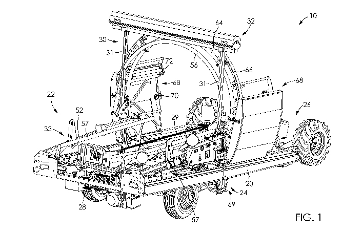
[00022] Figure 1 is a perspective view of a wrapping device with an end
surface
wrapping mechanism and a side surface wrapping mechanism according to an
embodiment.
[00023] Figure 2 is a side elevation view of the wrapping device of Figure 1.
[00024] Figure 3 is a perspective view of the wrapping device of Figure 1
shown
in combination with a bale in the receiving section and an end surface
wrapping
film shown across the wrapping section.
[00025] Figure 4 is another perspective view of the wrapping device of Figure
1
shown in combination with a bale in the bale receiving section and wrapped
with
an end surface wrapping film and a side surface wrapping film.
[00026] Figure 5 is a close-up perspective view of a portion of the end
surface
wrapping mechanism, according to an embodiment, and shown in an operative
configuration with an end surface film roll mounted thereon.
[00027] Figure 6 is a close-up perspective view of a portion of a wrapping
device
with the end surface wrapping mechanism and the side surface wrapping
mechanism according to an embodiment wherein the end surface wrapping
mechanism is shown in a dispensing configuration.
[00028] Figure 7 is a close-up perspective view of a first end of an end
surface
wrapping film source support of the end surface wrapping mechanism, according
to an embodiment.
6
CA 02906954 2015-09-15
WO 2014/139006
PCT/CA2014/050253
[00029] Figure 8 is a close-up perspective view of a second end of an end
surface wrapping film source support of the end surface wrapping mechanism,
according to an embodiment.
[00030] Figure 9 is a top perspective view of a wrapping device with a side
wrapping cutting mechanism, according to an embodiment, cutting arms of the
side wrapping cutting mechanism being shown in an extended configuration.
[00031 ] Figure 10 is a close up perspective view of an extendable arm and a
cutting assembly of a side wrapping cutting mechanism, according to an
embodiment, the cutting arm of the side wrapping cutting mechanism being
shown in an extended configuration.
[00032] Figure 11 is another close up perspective view of a cutting arm and a
cutting assembly of the side wrapping cutting mechanism, according to an
embodiment, the cutting arm of the side wrapping cutting mechanism being
shown in a retracted configuration.
DETAILED DESCRIPTION
[00033] In the following description, the same numerical references refer to
similar elements. The embodiments, geometrical configurations, materials
mentioned and/or dimensions shown in the figures or described in the present
description are embodiments only, given solely for exemplification purposes.
[00034] Moreover, although the embodiments of the wrapping device and
corresponding parts thereof consist of certain geometrical configurations as
explained and illustrated herein, not all of these components and geometries
are
essential and thus should not be taken in their restrictive sense. It is to be
understood, as also apparent to a person skilled in the art, that other
suitable
components and cooperation thereinbetween, as well as other suitable
geometrical configurations, may be used for the wrapping device, as will be
briefly explained herein and as can be easily inferred herefrom by a person
skilled in the art. Moreover, it will be appreciated that positional
descriptions such
7
CA 02906954 2015-09-15
WO 2014/139006
PCT/CA2014/050253
as "above", "below", "left", "right" and the like should, unless otherwise
indicated,
be taken in the context of the figures and should not be considered limiting.
[00035] Referring generally to Figures 1 to 4, in accordance with one
embodiment, there is provided an inline wrapping device 10 for wrapping at
least
one bale 12. The inline wrapping device 10 is configured such that it allows
the
wrapping of an end surface 14 of the at least one bale 12 as well as at least
a
longitudinal portion of the side surface 16 of the at least one bale 12. In
the
illustrated embodiment, the wrapping device 10 is an inline wrapper wherein
the
at least one bale 12 is moved longitudinally along a base frame 20 of the
wrapping device 10, between a bale receiving section 22 and a bale discharging
section 26. The wrapping (sealing) of the end surface 14 of the bale 12 as
well as
the longitudinal portion of the side surface 16 of the bale 12 occurs in a
wrapping
section 24 positioned between the bale receiving section 22 and a bale
discharging section 26.
[00036] One skilled in the art will understand that, even though the wrapping
device 10 is described herein as a device for wrapping at least one bale 12,
in an
embodiment, the device may be used for wrapping other types of loads differing
from bales of silage. Moreover, it will be understood that the wrapping device
10
may also be used for wrapping bales being sized and shaped differently from
the
bales shown in the appended figures. For example and without being !imitative,
the bales 12 could be square, rectangular or the like. It will also be
understood
that the wrapping device 10 may be used to wrap a single bale 12, and/or a
bale
assembly including more than one bale 12. In an embodiment (not shown) where
the wrapping device 10 is used to wrap a bale assembly including more than one
bale 12, the wrapping device 10 operates to wrap an end surface 14 and at
least
a section of a side surface 16 of the bale assembly in a similar manner used
to
wrap the end surface 14 and at least a section of the side surface 16 of a
single
bale 12, as described below, the difference being focused on the length of the
side surface 16 of the bale assembly as opposed to the length of the side
surface
16 of a single bale 12. For the sake of clarity, the description below will
now only
8
CA 02906954 2015-09-15
WO 2014/139006
PCT/CA2014/050253
refer to a single bale 12 to describe the wrapping device 10 and the method of
operation thereof.
[00037] In an embodiment, for moving the bale 12 between the different
sections
of the frame 20, a moving mechanism 28 is provided. In the illustrated
embodiment, the moving mechanism 28 is a hydraulic ram positioned in the bale
receiving section 22, and which pushes the bale 12 longitudinally from the
bale
receiving section 22 onto the bale wrapping section 24. In such an embodiment,
movement of a bale 12, along a transfer path following a longitudinal moving
axis
29, between the wrapping section 24 and the discharging section 26, occurs as
a
result of the bale 12 being pushed towards the discharging section 26 by a new
bale being inserted in the bale wrapping section 24, through the action of the
moving mechanism 28. One skilled in the art would however understand that, in
an alternative embodiment, a moving mechanism 28 operating differently than
the one described above could be used for moving the bale 12 between the
different sections of the frame 20. Moreover, in an embodiment (not shown),
the
bale may be pushed manually longitudinally by an operator, the moving
mechanism thereby only being configured to favor easy displacement of the bale
between the different sections, for example and without being !imitative, by
providing rollers for allowing the bale to be rolled longitudinally between
the
sections.
[00038] Still referring to Figures 1 to 4, in order to perform the wrapping of
an end
surface 14 of the bale 12 and at least a longitudinal portion of the side
surface 16
of the bale 12, in an embodiment, the wrapping device 10 includes an end
surface wrapping mechanism 30 and a side surface wrapping mechanism 60.
Each one of the end surface wrapping mechanism 30 and the side surface
wrapping mechanism 60 is mounted to the base frame 20, in the bale wrapping
section 24 thereof.
[00039] In an embodiment, the end surface wrapping mechanism 30 includes an
end surface film source support 32 into which an end surface film source 40
can
9
CA 02906954 2015-09-15
WO 2014/139006
PCT/CA2014/050253
be mounted and from which a length 38 of end surface film 36 can be dispensed,
as well as a retaining assembly 33 configured to maintain at least a portion
of the
length 38 of end surface film 36 across the bale wrapping section 24. In an
embodiment, the end surface film 36 is maintained across the bale wrapping
section 24 with a sufficient tension such as to be held tightly against the
end
surface 14 of the bale, upon engagement therebetween.
[00040] In the course of the present application, the expression "across the
bale
wrapping section" is understood to mean that the film extends substantially
perpendicularly to the longitudinal moving axis 29, in the wrapping section
24. In
other words, the end surface film 36 extends substantially vertically such as
to
engage a bale traveling longitudinally along the travel path, through the
wrapping
section.
[00041] Referring to Figures 5, 7 and 8, in an embodiment, the end surface
film
source support 32 has a first connector 42 at a first end and a second
connector
44 at a second end to engage and maintain the end surface film source 40. In
the
illustrated embodiment, the first connector 42 and second connector 44 are
receiving cylinders sized and shaped for receiving the central bore of a roll
of end
surface film 36. The second connector 44 includes a biasing assembly (not
shown) in order to allow the second connector 44 to be retracted in order to
insert or retrieve a roll of end surface film 36 between the first connector
42 and
the second connector 44 and subsequently bias the second connector towards
the first connector such that the roll of end surface film 36 is firmly
maintained
therebetween. In operation, the friction between the inner surface of a roll
of end
surface film 36 and the first connector 42 and second connector 44, when the
roll
of end surface film 36 rotates thereabout, results in a tension being imparted
and
maintained in the end surface film 36 being dispensed.
[00042] One skilled in the art will understand that, in alternative
embodiments
(not shown), other components or configurations could be used to maintain a
tension in the end surface film 36. For example and without being !imitative,
in an
CA 02906954 2015-09-15
WO 2014/139006
PCT/CA2014/050253
embodiment, the first connector 42 and second connector 44 could be rotatable
cylinders, rotating along with a roll of end surface film 36 mounted
therebetween.
In such an embodiment, the first connector 42 and second connector 44 may be
configured not to freely rotate, i.e. a frictional force impeding the free
rotation
thereof, in order to maintain a tension in the end surface film 36. In another
alternative embodiment (not shown), a tensioning mechanism may also be
provided to maintain a tension in the end surface film 36.
[00043] One skilled in the art will understand that, in alternative
embodiments,
other components or assembly, differing from the one described above, for
securing an end surface film source 40 to the end surface film source support
32
could also be used. For example and without being !imitative, in an
alternative
embodiment, the first connector may be a receiving cylinder sized and shaped
for
receiving the central bore of a roll of rolled film, mounted to a pivoting
member,
pivotable about a hinge and lockable in place using a locking member. The
second connector may be a locking connector composed of complementary
bevelled cylinders engaged to one another such that the diameter of the second
connector increases when the bevelled cylinders are pressed toward one
another, for lockingly engaging the central bore of the roll of rolled film. A
locking
handle may be operatively connected to the second connector for varying the
diameter of the second connector. Therefore, when a new roll of end surface
film
is received in the end surface film source support, the locking handle 45 can
be
used to secure the roll thereon, by increasing the diameter of the second
connector, such that the second connector is engaged with the central bore of
a
roll of rolled film in a press fit. Opposite action can be taken to release an
empty
roll therefrom.
[00044] In an embodiment, a cover 46 is further provided to protect the end
surface film source 40 mounted to the end surface wrapping film source support
32. The cover 46 may be pivotally mounted to allow easy covering/uncovering of
the end surface film source 40 in the end surface wrapping film source support
32.
11
CA 02906954 2015-09-15
WO 2014/139006
PCT/CA2014/050253
[00045]As can be seen more clearly in Figures 1 to 6, in an embodiment, the
end surface film source support 32 of the end surface wrapping mechanism 30 is
configurable in an operative configuration (as shown in Figures 1 to 5) and in
a
dispending configuration (as shown in Figure 6).
[00046] In the operative configuration, the end surface film source support 32
is
positioned above the wrapping section 24, at a distance sufficient for the
bale 12
to be moved between the frame and the end surface film source support 32. In
the operative configuration, the end surface film 36 extends downwardly from
the
end surface film source 40 contained in the end surface film source support
32,
across the wrapping section 24. Such a configuration allows an end surface 14
of
the bale 12 to contact and engage the end surface film 36, as it is moved
along
the longitudinal moving axis 29, into the wrapping section 24.
[00047] In the dispensing configuration, the end surface film source support
32 is
lowered towards the base frame 20, such that the end surface film source 40 is
easily accessible to an operator of the wrapping device 10. Therefore, when
the
end surface film source support 32 is positioned in the dispensing
configuration,
the operator of the wrapping device 10 can access the end surface film source
40, while standing on the ground, in order to pull a distal end 54 of the end
surface film 36 therefrom and connect the distal end 54 of the end surface
film 36
with the retaining assembly 33. It will be understood that, in an embodiment,
the
dispensing configuration can also be used to mount/dismount an end surface
film
source 40 onto the end surface film source support 32, for example in order to
replace the end surface film source 40 when the end surface film source 40 has
been emptied.
[00048] In an embodiment, in order to allow the end surface film source
support
32 to be shifted between the operative configuration and the dispensing
configuration, the end surface film source support 32 is mounted to pivoting
arms
31. The end surface film source support 32 is connected to the pivoting arms
31
at a distal end thereof and the pivoting arms 31 are pivotally mounted to the
12
CA 02906954 2015-09-15
PCT/CA2014/050253
14 January 2015 (14.01.2015)
International application number: CA2014050253
Article 34 Amendments submitted with Demand for IPEA dated 14 Jan 2015
frame 20 at a proximal end thereof. In order to allow the pivoting arms 31 to
pivot, the proximal end of the pivoting arm 31 may be connected to a hinge
assembly which allows pivoting thereof and securing of the arms 31 in either
one
of the operative configuration and the dispensing configuration.
[00049] One skilled in the art will understand that, in an alternative
embodiment
(not shown), the end surface wrapping mechanism 30 can include a dispensing
assembly in order to dispense end surface film 36 from the end surface film
source 40 configured in the operative configuration. In such an embodiment,
the
end surface film source 40 need not be configured in the above described
dispensing configuration in order to dispense end surface film 36 therefrom.
However the end surface film source 40 may be configured in the above
described dispensing configuration for replacement of the end surface film
source 40. In such an alternative embodiment, the dispensing assembly may
include a crank assembly operatively connected to the end surface film source
support 32 containing a roll of end surface film 36 as end surface film source
40.
In order to dispense end surface film 36 from the roll of end surface film 36,
a
crank of the crank assembly may be rotated to cause rotation of the roll of
end
surface film 36 and the consequent dispensing of end surface film 36
therefrom.
[00050] One skilled in the art will understand that even though the end
surface
film source 40 of the illustrated embodiment is a roll of rolled end surface
film 36,
in alternative embodiments, other types of sources for providing wrapping film
could be provided.
[00051]Moreover, in the illustrated embodiment where the end surface film
source 40 is a roll of rolled film, the film can be pre-cut in the roll, i.e.
the film may
have frangible connections between sections thereof. Therefore, in operation,
when the tension imparted on a frangible connection exceeds a threshold
tension, the length of end surface film 36 is separated from the end surface
film
source 40. Such a configuration allows the length of end surface film 36 to be
separated from the roll, for example after a predefined length has been
13
AMENDED SHEET
CA 02906954 2015-09-15
WO 2014/139006
PCT/CA2014/050253
dispensed, as a result of the breaking of the frangible connection causing a
separation between the roll and the length of end surface film 36. Regarding
the
separation between the length of end surface film 36 and the retaining
assembly
33, in the illustrated embodiment, such a separation occurs as a result of
tearing
caused by the pressure exerted on the end surface film 36 by the movement of
the bale 12 towards the discharging section 26.
[00052] One skilled in the art would understand that, in alternative
embodiments
(not shown), a cutting assembly (not shown) can be provided for cutting the
film
when required, the end surface film 36 may be manually cut by an operator
proximate to the end surface film source 40 and/or the retaining assembly 33
or
other components and/or mechanisms different from the ones of the illustrated
embodiment, may be used to separate the end surface film 36 from the end
surface film source 40 and/or the retaining assembly 33.
[00053] Now referring to Figures 1 to 6, as previously stated, a length 38 of
end
surface film 36 is dispensed from the end surface film source 40 and at least
a
portion of this length 38 of end surface film 36 is maintained across the bale
wrapping section 24 in order to engage the end surface of a bale 12 displaced
along the longitudinal moving axis 29. In the illustrated embodiment, the
length
38 of end surface film 36 is manually dispensed from the end surface film
source
40 and attached to the retaining assembly 33 when the end surface film source
support 32 is configured in the dispensing configuration and is increased as
the
end surface film source support 32 is pivoted into the operative
configuration.
[00054] The retaining assembly 33 includes attachment members 52 connected
to the frame 20 for receiving and retaining a portion of the end surface film
proximate to the distal end 54. Therefore, in the illustrated embodiment, the
operator can pull the distal end 54 of the end surface film 36 from the end
surface film source support 32, configured in the dispensing configuration, of
a
sufficient length 38 to reach the attachment members 52. Subsequently the
distal
end 54 of the end surface film 36 can be engaged into the attachment members
14
CA 02906954 2015-09-15
WO 2014/139006
PCT/CA2014/050253
52 such that it is maintained in place and the end surface film source support
32
can subsequently be configured in the operative configuration.
[00055] In the illustrated embodiments, the attachment members 52 are
positioned in the bale receiving section 22 of the frame 20. Such a
positioning of
the attachment members 52 ensures that a portion of the length 38 of end
surface film 36 extends below the side surface 16 of the bale 12. Therefore,
in an
embodiment, a portion of the length 38 of the end surface film 36 may extend
across the wrapping section 24 and a portion of the length 38 may extend in
the
receiving section 22, below the support supporting the bale in the bale
receiving
section 22.
[00056] One skilled in the art will understand that, even though the securing
of
the distal end 54 of the end surface film 36 to the attachment members 52 is
described herein as being made manually by an operator, in an alternative
embodiment, such securing could be automated. Indeed, in an alternative
embodiment, the dispensing of the length 38 of end surface film 36 and
subsequent securement of the distal end 54 thereof can be automated.
Moreover, in an embodiment, the shift between the dispensing configuration and
the operative configuration of the end surface film source support 32 could
also
be automated.
[00057] As can be seen in the illustrated embodiments, when a length 38 of end
surface film 36 is dispensed, the end surface film 36 has a length 38 and a
width
37 which cover more than the end surface 14 of the bale 12 and extend over the
outer edges of the end surface 14. In other words, when the end surface 14 of
the bale 12 engages the length 38 of end surface film 36, the length 38 of the
end surface film 36 should extend beyond a periphery of the end surface 14 and
expand into at least a section of the side surface 16 of the bale 12.
[00058] In an embodiment, end surface film guides are provided for guiding the
length of end surface film 36 towards the side surface of the bale 12. In an
embodiment, the end surface film guides includes an upper arch 56 positioned
CA 02906954 2015-09-15
WO 2014/139006
PCT/CA2014/050253
below the end surface film source support 32, and proximate thereto. In
operation, the upper arch 56 guides a portion of the end surface film 36
downward, from above, towards the side surface 16 of the bale 12, when the end
surface film source support 32 is configured in the operative configuration,
such
as to prevent the end surface film 36 to impede the action of the side surface
wrapping mechanism, which will be described below. In an embodiment, the end
surface film guides further includes lateral guides 57 positioned laterally
along
the longitudinal moving axis 29 of the transfer path. The lateral guides 57
are
configured and positioned to guide a portion of the end surface film 36
towards
the side surface 16 of the bale 12 laterally, thereby facilitating the
subsequent
dispensing of side surface wrapping along the side surface of the bale 12, as
will
be described below.
[00059]Now referring to Figures 1 to 4, the wrapping device 10 is further
provided with a side surface wrapping mechanism 60 mounted to the base frame
20. The side surface wrapping mechanism 60 is positioned in the bale wrapping
section 24, between the end surface wrapping mechanism 30 and the bale
discharging section 26.
[00060] As can easily be seen in Figure 4, the side surface wrapping mechanism
60 can dispense a length of side surface film 62 around at least a
longitudinal
portion of the side surface of the bale 12, thereby resulting in the sealing
of the
end surface 14 of the bale 12 by the end surface film 36. Indeed, in
operation,
when the bale 12 is moved into the wrapping section 24, the end surface 14 of
the bale 12 engages the end surface film 36 positioned across the wrapping
section 24. Given that the side surface wrapping mechanism 60 is positioned
subsequently to the end surface wrapping mechanism 30, the side surface film
62 provided around the side surface 16 of the bale 12 is wrapped around the
portion of end surface film exceeding the edges of the end surface 14 of the
bale
and maintains this exceeding portion against the side surface 16 thereof,
thereby
creating the desired sealing of the end surface 14 of the bale 12. One skilled
in
the art will understand that the side surface wrapping mechanism 60 may be
16
CA 02906954 2015-09-15
WO 2014/139006
PCT/CA2014/050253
used to cover the whole length of the side surface 16 of the bale 12 or only a
portion of the longitudinal section of the side surface 16 of the bale 12 that
is
sufficient for maintaining the exceeding portion of end surface film 36
against the
side surface 16.
[00061] One skilled in the art will understand that different side surface
wrapping
mechanisms 60 may be used to perform the desired wrapping of the side surface
16 by providing side surface film 62 around the side surface 16 thereof.
[00062]In an embodiment, the side surface wrapping mechanism 60 may
comprise a fixed inner hoop 64, a rotatable outer hoop 66 connected to the
outer
surface of the inner hoop 64, at least one cantilevered support 68 mounted on
the outer hoop 66 and a driving mechanism 69 operatively connected to the
outer
hoop 66 for rotating the outer hoop 66. In such an embodiment, the rotatable
outer hoop 66 is rotatably connected to the outer surface of the inner hoop 64
and has a shape that matches that of the inner hoop 64 to allow the outer hoop
66 to maintain a proximal relationship with the outer surface of the inner
hoop 64
during rotation. The cantilevered support 68 may include at least one spool
holder 70 for rotatably mounting a spool of side surface film 62 thereon and a
tensioning mechanism 72 for stretching the side surface wrapping film 62
before
the film is wrapped around the side surface 16 of the bale 12. The driving
mechanism 69 is operatively connected to the outer hoop 66 for rotating the
outer hoop 66 and thereby drives the cantilevered support 68 around the bale
12
to dispense side surface film 62.
[00063]A non-limitative embodiment of a wrapping device that may be used as
side wrapping mechanism is described in detail in the present Applicant's
United
States Patent Application No. 2012/0180430, which is incorporated herein by
reference.
[00064] Another non-limitative embodiment of a device that may be used for the
side wrapping mechanism is described in Canadian Patent Application No.
2,112,530, which is also incorporated herein by reference.
17
PCT/CA2014 /050253
5148458705 . CA 02906954 2015-09-15
04:42:10 PM 30 June 2015 30-06-2015
[00065] In view of the above, in order to perform the wrapping of an end
surface
and at least a portion of a side surface of at least one bale, using an inline
bale
wrapping device as described above, the following steps are performed. A bale
longitudinally movable along the transfer path, following a longitudinal axis,
is
received at a receiving end of the bale wrapping device. A length of end
surface
film is dispensed and maintained across the transfer path. As previously
mentioned, the length of end surface film is sized and shaped to extend beyond
a
periphery of the end surface of the bale. The length of end surface film may
be
dispensed and maintained across the transfer path by configuring the end
surface film source support in the dispensing configuration, pulling a length
of
end surface film from the end surface film source and engaging the end surface
film to attachment members and configuring the end surface film source support
in the operative configuration. The bale is subsequently moved longitudinally
along the transfer path such as to engage its end surface with the end surface
film and a side surface film is wrapped around a side surface of the bale,
over a
portion of the end surface film extending beyond the periphery of the end
surface
of the bale.
[00066] One skilled in the art will understand that the above described
wrapping
device 10 and method of operation described above are destined to seal one end
surface of a bale. However, when sealing of a second end surface is desired,
the
bale can be inverted and wrapped a second time using the same wrapping
device and method for sealing the opposed end surface.
[00067] Now referring to Figures 9 to 11, in an embodiment, the wrapping
device
may further include a side wrapping cutting mechanism 80 mounted to the
frame 20. The side wrapping cutting mechanism 80 allows the cutting and
holding of the side surface film 62, subsequently to the cutting operation.
[00068] In the illustrated embodiment, the side wrapping cutting mechanism 80
includes two extendable arms 82 formed of cutting shafts 82a, 82b and
corresponding cutting assemblies 84. In an embodiment, the extendable arms 82
18
PAGE 7111* RCVD AT 613012015 4:52:24 PM [Eastern Daylight Time)* SVR:F00003120
* DNIS:3905* CSID:5148458705* DURATION (111M-SS):01-59
AMENDED SHEET
CA 02906954 2015-09-15
WO 2014/139006
PCT/CA2014/050253
are operated simultaneously to sever the side surface film between the source
and the bale 12. One skilled in the art will understand the amount of arms 82
and
corresponding cutting assemblies 84 may be varied to operate with different
side
surface wrapping mechanisms 60. Moreover it will be understood that in
alternative embodiments, the arms 82 and corresponding cutting assemblies 84
may be operated independently.
[00069] One skilled in the art will also understand that the term "extendable
arm"
is used herein to refer to a component which can be extended and retracted and
that in different embodiments, different components or assembly resulting in
longitudinal movement and capable of pulling a section of side surface film
62,
when retracted, as will be described in more details below, could be used.
Moreover, in the illustrated embodiment, each retractable arm 82 is composed
of
three extendable shafts 82a, 82b, but one skilled in the art will understand
that a
different amount of cooperating shafts may be used.
[00070] Since the operation of each arm 82, along with the corresponding
cutting
assembly 84 is similar, the operation of one of the arm 82 will be described
below. However, one skilled in the art will understand that more than one arm
82
may operate concurrently, similarly to what is described below.
[00071] The extendable arm 82 has an abutment member 83 at a first end
thereof and is configurable between an extended configuration (shown in
Figures
9 and 10) and a retracted configuration (shown in Figure 11). In an
embodiment,
the extendable arm 82 is composed of a central shaft 82a extending from a
hydraulic cylinder 90 and lateral shafts 82b. However, one skilled in the art
will
understand that, in alternative embodiments, other types of mechanisms for
providing an extendable arm could be used. For example and without being
!imitative, a pneumatic cylinder may be used instead of a hydraulic cylinder.
The
cutting assembly 84 also includes a resilient member 86 and a fixed blade 88.
[00072] When the extendable arm 82 is configured in the extended configuration
(shown in Figures 9 and 10), the extendable arm 82 extends away from the
19
CA 02906954 2015-09-15
WO 2014/139006
PCT/CA2014/050253
cutting assembly 84, i.e. the abutment member 83 of the extendable arm 82 is
spaced apart from the cutting assembly 84. In such a configuration, the arm 82
extends at least over a length sufficient for the abutment member 83 to be
past
the side surface film that is dispensed by the side surface wrapping mechanism
60. In other words, the arm 82 must extend longitudinally of a distance
greater
than the width of the side surface film 62 dispensed by the side surface
wrapping
mechanism 60.
[00073] Now referring to Figure 11, when the extendable arm 82 is configured
in
the retracted configuration, the abutment member reaches the fixed blade 88,
and is further retracted such that the front end of the fixed blade enters a
receiving cavity 83a formed therein and the abutment member 83 is pressed
against the resilient member 86 of the cutting assembly 84.
[00074] In an alternative embodiment (not shown), the resilient member may be
provided between the fixed blade and the abutment member of the arm.
Therefore when the extendable arm is configured in the retracted
configuration,
the abutment member is pressed against the resilient member of the cutting
assembly and can subsequently be further retracted to contract the resilient
member until the abutment member reaches the fixed blade.
[00075] Using the side wrapping cutting mechanism 80 of the illustrated
embodiment, in operation, the following steps are provided for each extendable
arm and corresponding cutting assembly, for cutting the side surface film 62.
Firstly, a length of side surface wrapping film 62 is dispensed around the
bale 12
by the side surface film wrapping mechanism 60, while the extendable arm 82 is
maintained in the retracted configuration. Subsequently, the extendable arm 82
is
configured in the extended configuration and extends proximate to the side
surface 16 of the bale 12. As previously stated, the extendable arm 82 extends
at
least over a length sufficient for the abutment member 83 to be past the
extremity
of the side surface film 62 that is distal from the cutting assembly 84,
thereby
spanning at least the width of the side surface wrapping film 62. Once the
CA 02906954 2015-09-15
WO 2014/139006
PCT/CA2014/050253
extendable arm 82 is configured in the extended configuration, an additional
length of side surface wrapping film 62 is dispensed around the side surface
16
of the bale 12, using the side surface film wrapping mechanism 60. Given the
position of the extended extendable arm 82, the dispensing of the additional
length of side surface film 62 results in the side surface film 62 being
wrapped
over the extendable arm 82. Subsequently, the extendable arm 82 is retracted
towards the cutting assembly 84, in the retracted configuration. The
retraction of
the extendable arm 82 causes the section of side surface film 62 which extends
over the cutting shaft 82 to be pulled towards the blade 88 and resilient
member
86 of the cutting assembly 84 and to be substantially simultaneously
sandwiched
between the abutment member 83 and the resilient member 86 and cut by the
cutting blade 88. Consequently, the side surface film 62 can be cut and the
section of side surface film is still held between the resilient member 86 and
the
abutment member 83. One skilled in the art will understand that the position
of
the blade 88 with regards to the resilient member 86 is configured to sever
the
side surface film 62 at a location that allows the portion of film attached to
the
bale to be released and the section of film that is attached to the film
source to be
maintained between the abutment member 83 and the resilient member 86.
[00076] In the alternative embodiment (not shown) where the resilient member
is
provided between the fixed blade and the abutment member of the arm, further
retraction of the arm 82 is required to cause the resilient member 86 to be
contracted until the section of side surface film 62 is severed against the
blade
88 located behind the resilient member 86.
[00077] It will be understood that, in alternative embodiments, different
components or assemblies resulting in a longitudinal movement of a component
along the side surface of the bale and capable of pulling a section of side
surface
film towards a cutting assembly, where the side surface film is cut and a
section
is released while another section of side surface film is maintained thereon,
could
be used. One skilled in the art will understand that accordingly, the steps of
a
21
CA 02906954 2015-09-15
WO 2014/139006
PCT/CA2014/050253
corresponding method of operation could also differ from the one described
above.
[00078]Several alternative embodiments and examples have been described
and illustrated herein. The embodiments described above are intended to be
exemplary only. A person skilled in the art would appreciate the features of
the
individual embodiments, and the possible combinations and variations of the
components. A person skilled in the art would further appreciate that any of
the
embodiments could be provided in any combination with the other embodiments
disclosed herein. It is understood that the invention may be embodied in other
specific forms without departing from the central characteristics thereof. The
present examples and embodiments, therefore, are to be considered in all
respects as illustrative and not restrictive, and the invention is not to be
limited to
the details given herein. Accordingly, while specific embodiments have been
illustrated and described, numerous modifications come to mind without
significantly departing from the scope of the invention as defined in the
appended
claims.
22