Sélection de la langue

Search

Sommaire du brevet 2907975 

Énoncé de désistement de responsabilité concernant l'information provenant de tiers

Une partie des informations de ce site Web a été fournie par des sources externes. Le gouvernement du Canada n'assume aucune responsabilité concernant la précision, l'actualité ou la fiabilité des informations fournies par les sources externes. Les utilisateurs qui désirent employer cette information devraient consulter directement la source des informations. Le contenu fourni par les sources externes n'est pas assujetti aux exigences sur les langues officielles, la protection des renseignements personnels et l'accessibilité.

Disponibilité de l'Abrégé et des Revendications

L'apparition de différences dans le texte et l'image des Revendications et de l'Abrégé dépend du moment auquel le document est publié. Les textes des Revendications et de l'Abrégé sont affichés :

  • lorsque la demande peut être examinée par le public;
  • lorsque le brevet est émis (délivrance).
(12) Brevet: (11) CA 2907975
(54) Titre français: STATOR DE GENERATEUR SYNCHRONE ET GENERATEUR SYNCHRONE
(54) Titre anglais: SYNCHRONOUS GENERATOR STATOR AND SYNCHRONOUS GENERATOR
Statut: Périmé et au-delà du délai pour l’annulation
Données bibliographiques
(51) Classification internationale des brevets (CIB):
  • H02K 01/18 (2006.01)
  • H02K 05/24 (2006.01)
(72) Inventeurs :
  • ROER, JOCHEN (Allemagne)
  • FEITH, MANUEL (Allemagne)
  • JEPSEN, TORSTEN (Allemagne)
(73) Titulaires :
  • WOBBEN PROPERTIES GMBH
(71) Demandeurs :
  • WOBBEN PROPERTIES GMBH (Allemagne)
(74) Agent: OYEN WIGGS GREEN & MUTALA LLP
(74) Co-agent:
(45) Délivré: 2016-11-29
(86) Date de dépôt PCT: 2014-04-11
(87) Mise à la disponibilité du public: 2014-11-06
Requête d'examen: 2015-09-24
Licence disponible: S.O.
Cédé au domaine public: S.O.
(25) Langue des documents déposés: Anglais

Traité de coopération en matière de brevets (PCT): Oui
(86) Numéro de la demande PCT: PCT/EP2014/057377
(87) Numéro de publication internationale PCT: EP2014057377
(85) Entrée nationale: 2015-09-24

(30) Données de priorité de la demande:
Numéro de la demande Pays / territoire Date
10 2013 207 931.1 (Allemagne) 2013-04-30

Abrégés

Abrégé français

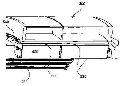
La présente invention concerne un stator de générateur synchrone présentant une bague de stator (300), un paquet de tôles de stator (400), un entrefer rotatif (310) entre la bague de stator (300) et le paquet de tôles de stator (400), ainsi qu'une pluralité d'unités de découplage (500) situées dans l'entrefer (310). L'unité de découplage (500) présente une première tôle (510) adaptée au contour du paquet de tôles de stator (400), et une seconde tôle (530) adaptée au contour de la bague de stator (300). Un mat (520) avec une cavité et une soupape d'admission (540) est prévu entre la première et la seconde tôle (510, 530).


Abrégé anglais

The invention relates to a synchronous generator stator comprising a stator ring (300), a stator laminated core (400), a continuous gap (310) between the stator ring (300) and the stator laminated core (400) and a plurality of decoupling units (500) in said gap (310), the decoupling unit (500) having a first metal sheet (510) that is adapted to the contour of the stator laminated core (400) and a second metal sheet (530) that is adapted to the contour of the stator ring (300). A mat (520) comprising a hollow chamber and an inlet valve (540) is provided between the first and the second metal sheet (510, 530).

Revendications

Note : Les revendications sont présentées dans la langue officielle dans laquelle elles ont été soumises.


-7-
Claims
1. Synchronous-generator stator, comprising
a stator ring (300),
a stator core (400),
a circumferential gap (310) between the stator ring (300) and the stator core
(400),
and
a plurality of decoupling units (500) in the gap (310), wherein
the decoupling unit (500) has a first plate (510), which is matched to a
contour of
the stator core (400), and has a second plate (530), which is matched to the
contour of
the stator ring (300),
wherein a mat (520), having a cavity and an inlet valve (540), is provided
between
the first and the second plate (510, 530).
2. Synchronous-generator stator according to Claim 1, wherein
the mat (520) is designed as a vulcanised-in rubber pressure mat.
3. Synchronous generator, comprising
a synchronous-generator stator, which has
a stator ring (300),
a stator core (400),
a circumferential gap (310) between the stator ring (300) and the stator core
(400),
and
a plurality of decoupling units (500) in the gap (310),
wherein the decoupling unit (500) has a first plate (510), which is matched to
a
contour of the stator core (400), and has a second plate (530), which is
matched to the
contour of the stator ring (300),
wherein a mat (520), having a cavity and an inlet valve (540), is provided
between
the first and the second plate (510, 530).
4. Wind turbine having a synchronous generator according to Claim 3.
5. Method for mounting a synchronous-generator stator that has a stator
ring (300)
and a stator core (400), comprising the steps:
inserting the stator core (400) in a stator ring (300), such that there is a
circumferential gap (310) between the stator ring (300) and the stator core
(400),
inserting a plurality of decoupling units (500) in the gap (310), wherein

-8-
the decoupling unit (500) has a first plate (510), which is matched to a
contour of
the stator core (400), and has a second plate (530), which is matched to the
contour of
the stator ring (300),
wherein a mat (520), having a cavity and an inlet valve (540), is provided
between
the first and the second plate (510, 530), additionally comprising the step:
introducing a pressure medium via the inlet valve (540) in the decoupling unit
(500), in order to fill a cavity of the mat (520) between a first and a second
plate (510,
530), after the plurality of decoupling units (500) have been inserted in the
gap (310).

Description

Note : Les descriptions sont présentées dans la langue officielle dans laquelle elles ont été soumises.


CA 02907975 2015-09-24
. ,
Synchronous generator stator and synchronous generator
The present invention relates to a synchronous-generator stator and to a
synchronous
generator.
Synchronous generators are used, for example, in wind turbines, and have a
generator
stator and a generator rotor. The generator stator is typically fixedly
connected to a
nacelle of a wind turbine, and the generator rotor is coupled directly or
indirectly (via a
transmission) to a rotor of the wind turbine. As the rotor of a wind turbine
rotates, the
generator rotor of the synchronous generator thus rotates concomitantly, such
that the
synchronous generator generates electrical energy.
It is an object of the invention to provide a synchronous generator for a wind
turbine that
makes it possible to achieve a reduction in acoustic emission.
This object is achieved by a synchronous-generator stator according to Claim 1
and by a
synchronous generator according to Claim 4.
The invention provides a synchronous-generator stator, comprising a stator
ring, a stator
core, a circumferential gap between the stator ring (or its inner or outer
contour) and the
stator core (or its outer or inner core), and a plurality of decoupling units
in the gap.
The decoupling unit has a first plate, which is matched to the (outer) contour
of the stator
core, and has a second plate, which is matched to the (inner) contour of the
stator ring. A
mat, having a cavity and an inlet valve, is provided between the first and the
second
plate.
The gap may be in the form of an annular gap.
The cavity can be filled with a pressure medium, through the inlet valve.

CA 02907975 2015-09-24
- 2 -
According to one aspect of the present invention, the mat is designed as a
vulcanised-in
rubber pressure mat.
The invention also relates to a synchronous generator comprising a synchronous-
generator stator according to the invention.
The invention also relates to a method for mounting a synchronous-generator
stator that
has a stator ring and a stator core. The stator core is inserted in a stator
ring, such that
there is a circumferential gap between a contour of the stator ring and a
contour of the
stator core. A plurality of decoupling units are inserted in the gap.
According to a further aspect of the present invention, a pressure medium is
introduced
io into the decoupling unit, via an inlet valve, in order to fill a cavity
of the mat between the
first and the second plate, after the plurality of decoupling units have been
inserted in the
gap.
The invention also relates to a wind turbine having a synchronous generator
comprising a
synchronous-generator stator according to the invention.
The invention relates to a concept of providing a synchronous-generator stator
that has a
plurality of decoupling units in a gap between a stator ring and a stator
core. These
decoupling units may be provided in order to avoid transmission of vibrations
or structure-
borne noise from the stator core to the stator ring.
According to one aspect of the invention, a decoupling element has an outer
and an inner
plate part, and has a flexible mat such as, for example, a rubber pressure mat
between
these parts.
The synchronous generator may be designed as an internal rotor, i.e. the rotor
of the
generator is provided inside the stator.
The mat between the two plates of the decoupling unit may have a cavity, such
that a
pressure medium can be introduced into this cavity. The decoupling elements
may thus
first be inserted, without a pressure medium, in the gap between the stator
ring and the
stator core, in order then subsequently to introduce a pressure medium, such
that the
decoupling elements fill the gap between the stator ring and the stator core
(with increase
in thickness).

CA 02907975 2015-09-24
- 3 -
Further designs of the invention constitute subject-matter of the dependent
claims.
Advantages and exemplary embodiments of the invention are explained in greater
detail
in the following with reference to the drawing.
Fig. 1 shows a schematic representation of a wind turbine
according to the invention,
Fig. 2 shows a perspective representation of a synchronous-
generator stator according to a first exemplary embodiment,
Figs. 3A and 3B each show a perspective view of a decoupling unit for
a
synchronous generator stator according to the first exemplary
embodiment,
Fig. 4 shows a schematic, perspective view of a portion of
the
synchronous generator according to the first exemplary
embodiment,
Fig. 5 shows a further schematic, perspective view of a
portion of
the synchronous-generator stator according to the first
exemplary embodiment, and
Fig. 6 shows a perspective sectional view of a synchronous-
generator stator according to the first exemplary
embodiment.
Fig. 1 shows a schematic representation of a wind turbine according to the
invention.
The wind turbine 100 has a tower 102 and a nacelle 104. A rotor 106, having
three rotor
blades 108 and a spinner 110, is provided on the nacelle 104. When in
operation, the
rotor 106 is put into a rotary motion by the wind, and thus also rotates the
rotor of a
synchronous generator in the nacelle 104. The pitch angle of the rotor blades
108 can be
altered by pitch motors at the blade roots of the respective rotor blades 108.
The synchronous-generator stator of the synchronous generator is typically
fixedly
connected to the nacelle of the wind turbine, while the rotor of the
synchronous generator
is coupled directly (or via a transmission) to the aerodynamic rotor of the
wind turbine,
such that the generator rotor rotates when the aerodynamic rotor of the wind
turbine
rotates.

CA 02907975 2015-09-24
- 4 -
The realization of an internal rotor is described in the following. In the
case of an external
rotor, "inner" and "outer" are to be interchanged.
Fig. 2 shows a perspective representation of a synchronous-generator stator
according to
a first exemplary embodiment. The stator has an outer stator ring 300, an
inner stator
core 400, and a circumferential gap 310 between the outer surface of the
stator core 400
and the inner surface of the stator ring 300. A plurality of decoupling units
500 are
provided in this circumferential gap 310. The decoupling units 500 serve to
decouple
vibration and/or structure-borne noise between the stator core 400 and the
stator ring
300.
Figs. 3A and 3B each show a perspective view of a decoupling unit for a
synchronous-
generator stator according to the first exemplary embodiment. The decoupling
unit 500
has a first and a second plate 510, 530, and has a mat 520 between the first
and the
second plate 510, 530. The first plate 510 is matched to the outer contour of
the stator
core 400. The second plate 530 is matched to the inner contour of the stator
ring 300.
The decoupling units 500 are arranged in the manner of circle segments in the
circumferential gap 310. Two fastening lugs 511, for example, may be provided
on the
first plate 510, and two fastening lugs 531 may be provided on the second
plate 530.
These lugs 511, 531 are provided on an end face of the decoupling unit 500.
The mat
520 between the first and the second plate 510, 530 may have a cavity that can
be filled
with a pressure medium, via an inlet valve 540 on the end face of the
decoupling unit 500.
According to one aspect of the present invention, the first and the second
decoupling
plate are approximately 2 mm thick, and the mat 520 is constituted by a
vulcanised-in
rubber pressure mat.
Fig. 4 shows a schematic, perspective view of a portion of the synchronous
generator
according to the first exemplary embodiment. In particular, Fig. 4 shows a
decoupling
element 500 when inserted in a circumferential gap 310 between the stator ring
300 and
the stator core 400. In this case, the decoupling element 500 is inserted in
the gap 310.
Optionally in this case, the mat 520 may be provided, for example, between the
first and
the second plate 510, 530 without a pressure medium, such that it is more
easily inserted.
Fig. 5 shows a further schematic, perspective view of a portion of the
synchronous-
generator stator according to the first exemplary embodiment. The synchronous-
generator stator has a stator ring 300, a stator core 400, and a
circumferential gap 310

CA 02907975 2015-09-24
- 5 -
between the stator ring 300 and the stator core 400. A plurality of decoupling
units 500
are placed, or inserted, in this gap. After the decoupling units 500 have been
inserted in
the circumferential gap 310, a pressure medium can be introduced into the
cavity of the
mat 520 by means of the inlet valve 540. This has the result that the distance
between
the first and the second plate 510, 530 is increased, until the first plate
bears against the
outer contour of the stator core 400 and the second plate 530 bears against
the inner
contour of the stator ring 300.
Fig. 6 shows a perspective sectional view of a synchronous-generator stator
according to
the first exemplary embodiment. The synchronous-generator stator has a stator
ring 300,
a stator core 400, and a gap 310 between the stator ring 300 and the stator
core 400. A
plurality of decoupling units 500 are provided in this gap 310. The decoupling
unit 500
has a first and a second plate 510, 530, and has a mat 520 between these
plates. The
design of the decoupling units according to Fig. 6 may be based on a
decoupling unit
according to Figs. 3A and 3B.
The decoupling units are thus provided between the stator core 400 and the
stator ring
300.
A pressure medium can be introduced into the cavity of the mat by means of the
inlet
valve 540, such that the gap between the stator ring 300 and the core 400 can
be filled
and pressure-injected for the purpose of transmitting torque. The decoupling
elements
can also be used for setting the air gap of the generator.
According to the invention, the use of the decoupling units in the gap between
the stator
ring 300 and the stator core makes it possible to provide decoupling of
structure-borne
noise and/or decoupling of vibration, such that the acoustic emission of the
synchronous
generator can be reduced considerably.
The synchronous generator according to the invention is constituted by a
slowly rotating
synchronous generator, and in particular a ring generator, for a wind turbine
or
hydropower installation. The synchronous generator has a rated power of > 1
MW. The
synchronous generator has a rotational speed of under 40 rpm, and in
particular of under
20 rpm.

CA 02907975 2015-09-24
- 6 -
Provided according to the invention is a synchronous generator having a
diameter of
> 4 m. Moreover, the synchronous generator is designed as a separately excited
synchronous generator.

Dessin représentatif
Une figure unique qui représente un dessin illustrant l'invention.
États administratifs

2024-08-01 : Dans le cadre de la transition vers les Brevets de nouvelle génération (BNG), la base de données sur les brevets canadiens (BDBC) contient désormais un Historique d'événement plus détaillé, qui reproduit le Journal des événements de notre nouvelle solution interne.

Veuillez noter que les événements débutant par « Inactive : » se réfèrent à des événements qui ne sont plus utilisés dans notre nouvelle solution interne.

Pour une meilleure compréhension de l'état de la demande ou brevet qui figure sur cette page, la rubrique Mise en garde , et les descriptions de Brevet , Historique d'événement , Taxes périodiques et Historique des paiements devraient être consultées.

Historique d'événement

Description Date
Le délai pour l'annulation est expiré 2022-10-12
Lettre envoyée 2022-04-11
Lettre envoyée 2021-10-12
Lettre envoyée 2021-04-12
Inactive : COVID 19 - Délai prolongé 2020-03-29
Représentant commun nommé 2019-10-30
Accordé par délivrance 2016-11-29
Inactive : Page couverture publiée 2016-11-28
Préoctroi 2016-10-14
Inactive : Taxe finale reçue 2016-10-14
Un avis d'acceptation est envoyé 2016-07-05
Lettre envoyée 2016-07-05
Un avis d'acceptation est envoyé 2016-07-05
Inactive : Approuvée aux fins d'acceptation (AFA) 2016-06-22
Inactive : Q2 réussi 2016-06-22
Requête pour le changement d'adresse ou de mode de correspondance reçue 2016-02-03
Lettre envoyée 2015-11-19
Inactive : Transfert individuel 2015-11-10
Inactive : CIB attribuée 2015-10-16
Demande reçue - PCT 2015-10-16
Inactive : CIB en 1re position 2015-10-16
Lettre envoyée 2015-10-16
Inactive : Acc. récept. de l'entrée phase nat. - RE 2015-10-16
Exigences pour l'entrée dans la phase nationale - jugée conforme 2015-09-24
Exigences pour une requête d'examen - jugée conforme 2015-09-24
Toutes les exigences pour l'examen - jugée conforme 2015-09-24
Demande publiée (accessible au public) 2014-11-06

Historique d'abandonnement

Il n'y a pas d'historique d'abandonnement

Taxes périodiques

Le dernier paiement a été reçu le 2015-09-24

Avis : Si le paiement en totalité n'a pas été reçu au plus tard à la date indiquée, une taxe supplémentaire peut être imposée, soit une des taxes suivantes :

  • taxe de rétablissement ;
  • taxe pour paiement en souffrance ; ou
  • taxe additionnelle pour le renversement d'une péremption réputée.

Les taxes sur les brevets sont ajustées au 1er janvier de chaque année. Les montants ci-dessus sont les montants actuels s'ils sont reçus au plus tard le 31 décembre de l'année en cours.
Veuillez vous référer à la page web des taxes sur les brevets de l'OPIC pour voir tous les montants actuels des taxes.

Historique des taxes

Type de taxes Anniversaire Échéance Date payée
Requête d'examen - générale 2015-09-24
Taxe nationale de base - générale 2015-09-24
TM (demande, 2e anniv.) - générale 02 2016-04-11 2015-09-24
Enregistrement d'un document 2015-11-10
Taxe finale - générale 2016-10-14
TM (brevet, 3e anniv.) - générale 2017-04-11 2017-03-28
TM (brevet, 4e anniv.) - générale 2018-04-11 2018-03-29
TM (brevet, 5e anniv.) - générale 2019-04-11 2019-04-03
TM (brevet, 6e anniv.) - générale 2020-04-14 2020-03-31
Titulaires au dossier

Les titulaires actuels et antérieures au dossier sont affichés en ordre alphabétique.

Titulaires actuels au dossier
WOBBEN PROPERTIES GMBH
Titulaires antérieures au dossier
JOCHEN ROER
MANUEL FEITH
TORSTEN JEPSEN
Les propriétaires antérieurs qui ne figurent pas dans la liste des « Propriétaires au dossier » apparaîtront dans d'autres documents au dossier.
Documents

Pour visionner les fichiers sélectionnés, entrer le code reCAPTCHA :


Pour visualiser une image, cliquer sur un lien dans la colonne description du document. Pour télécharger l'image (les images), cliquer l'une ou plusieurs cases à cocher dans la première colonne et ensuite cliquer sur le bouton "Télécharger sélection en format PDF (archive Zip)" ou le bouton "Télécharger sélection (en un fichier PDF fusionné)".

Liste des documents de brevet publiés et non publiés sur la BDBC .

Si vous avez des difficultés à accéder au contenu, veuillez communiquer avec le Centre de services à la clientèle au 1-866-997-1936, ou envoyer un courriel au Centre de service à la clientèle de l'OPIC.


Description du
Document 
Date
(aaaa-mm-jj) 
Nombre de pages   Taille de l'image (Ko) 
Description 2015-09-23 6 209
Revendications 2015-09-23 2 48
Dessins 2015-09-23 6 104
Abrégé 2015-09-23 1 13
Dessin représentatif 2015-10-18 1 7
Dessin représentatif 2016-11-20 1 10
Accusé de réception de la requête d'examen 2015-10-15 1 174
Avis d'entree dans la phase nationale 2015-10-15 1 201
Courtoisie - Certificat d'enregistrement (document(s) connexe(s)) 2015-11-18 1 126
Avis du commissaire - Demande jugée acceptable 2016-07-04 1 163
Avis du commissaire - Non-paiement de la taxe pour le maintien en état des droits conférés par un brevet 2021-05-24 1 550
Courtoisie - Brevet réputé périmé 2021-11-01 1 535
Avis du commissaire - Non-paiement de la taxe pour le maintien en état des droits conférés par un brevet 2022-05-23 1 551
Modification - Abrégé 2015-09-23 2 85
Demande d'entrée en phase nationale 2015-09-23 4 128
Rapport de recherche internationale 2015-09-23 3 73
Correspondance 2016-02-02 10 793
Taxe finale 2016-10-13 1 48