Note : Les descriptions sont présentées dans la langue officielle dans laquelle elles ont été soumises.
CA 02908384 2015-09-28
Attorney Docket No. 1186P005CA01
APPARATUS AND METHOD FOR OPERATING DISTRIBUTED GENERATOR IN
CONNECTION WITH POWER SYSTEM
TECHNICAL FIELD
The present invention relates to an apparatus and a method for operating a
distributed generator in connection with a power system, and more
particularly, to an
apparatus and a method for operating a distributed generator in connection
with a
power system in which voltage fluctuations at a point of common coupling with
the
distributed generator are restrained to prevent a voltage at the point of
common
coupling with the distributed generator from exceeding an allowable limit when
the
distributed generator is connected with the power system.
BACKGROUND OF THE INVENTION
When a distributed generator is connected with a distribution system, a
voltage at
a point of common coupling with the distributed generator is increased by
active power
of the distributed generator injected into the distribution system.
The voltage at the point of common coupling with the distributed generator is
increased because an active output is injected into a point of common coupling
with the
distribution system in such a way that a flow of power from the point of
common
coupling to a substation, that is, a normal direction flow of power in the
distribution
system and a reverse direction flow of power occur, thereby increasing the
voltage to a
degree of the product of a current and a line impedance at that time.
Accordingly, power suppliers restrict a capacity of the distributed generator
in
connection with a distribution system to prevent a voltage at a point of
common coupling
with the distributed generator from exceeding a tolerance range due to the
distributed
generator.
1
CA 02908384 2015-09-28
Attorney Docket No. 1186P005CA01
Particularly, it is difficult to additionally connect a distributed generator
with a
distribution line in connection with existing distributed generators due to .a
voltage rise at
a point of common coupling with the distributed generator. This is because
applications
for connecting a distributed generator converge on regions having similar
location
requirements. Also, as a result, even though a capacity of a distributed
generator to be
newly connected is small, it may be impossible to connect.
To connect a distributed generator not allowed to be connected, it is
necessary to
detect a new point of common coupling with the distributed generator at
another
distribution line or to build a new exclusive distribution line from a
substation. However,
in this case, it is impossible to start business due to excessive costs.
Such technical limitation of conventional technologies socially causes a loss
in
opportunity cost and becomes an obstacle in a new renewable energy supply
policy and
an eco-friendly policy for restraining carbon dioxide discharge.
The related art of the present invention is disclosed in Korea Patent
Publication
No. 10-2012-0025121 (March 15, 2012) under the title of "An optimal voltage
control
system and method for dispersed generation interconnected primary distribution
line."
SUMMARY OF INVENTION
An aspect of the present invention is to provide an apparatus and method for
operating a distributed generator in connection with a power system, which
restrain
voltage fluctuations at a point of common coupling with the distributed
generator by
compensating a voltage rise portion at the point of common coupling with the
distributed
generator caused by an active output of the distributed generator with a
voltage drop
portion of a reactive output of the distributed generator.
2
CA 02908384 2015-09-28
Attorney Docket No. 1186P005CA01
An aspect of the present invention is to also provide an apparatus and method
for operating a distributed generator in connection with a power system, which
increase
a connection capacity of the distributed generator at the same distribution
line.
An aspect of the present invention is to also provide an apparatus and method
for operating a distributed generator in connection with a power system, which
promote
the distributed generator whose generation source is a new renewable energy
source
by reducing distributed generator connection costs and efficiently operate
power
facilities by maximizing a utilization rate of a distribution line.
An aspect of the present invention is to also provide an apparatus and method
for operating a distributed generator in connection with a power system, which
provide
an appropriate solution depending on information communication infrastructure
conditions of a connected distribution line by providing an operation method
in
connection with an host operation system with the support of an information
communication infrastructure and applying a locally optimized solution
performed
without the support of the information communication infrastructure.
One aspect of the present invention provides an apparatus for operating a
distributed generator in connection with a power system. The apparatus
includes an
input unit which receives a parameter calculated using power system
information and a
voltage and a current at a point of common coupling with the distributed
generator, with
which the distributed generator is connected, a calculation unit which
calculates an
operating power factor instruction value and an active output instruction
value using the
parameter and the voltage and current at the point of common coupling with the
distributed generator input to the input unit, and a control communication
unit which
determines and transmits the operating power factor instruction value and the
active
output instruction value according to the voltage at the point of common
coupling with
the distributed generator input to the input unit and an admissible voltage
upper limit at
the point of common coupling with the distributed generator to the distributed
generator.
3
CA 02908384 2015-09-28
Attorney Docket No. 1186P005CA01
The control communication unit may determine the active output instruction
value
as an allowable active power generation amount of the distributed generator
when the
voltage at the point of common coupling with the distributed generator input
to the input
unit exceeds the admissible voltage upper limit at the point of common
coupling with the
distributed generator.
The control communication unit may determine the active output instruction
value
as a preset first set value when the voltage at the point of common coupling
with the
distributed generator input to the input unit is the admissible voltage upper
limit at the
point of common coupling with the distributed generator or less.
The control communication unit may compare a present instantaneous active
power output amount of the distributed generator with a regular optimal active
power
generation amount and may determine the operating power factor instruction
value
according to a comparison result when the voltage at the point of common
coupling with
the distributed generator input to the input unit is the admissible voltage
upper limit at
the point of common coupling with the distributed generator or less.
The control communication unit may determine the operating power factor
instruction value as a second set value when the present instantaneous active
power
output amount is the regular optimal active power generation amount or less.
The control communication unit may calculate the operating power factor
instruction value to compensate a voltage rise portion at the point of common
coupling
with the distributed generator with a voltage drop portion caused by the
reactive output
when the present instantaneous active power output amount exceeds the regular
optimal active power generation amount.
The operating power factor instruction value may be a ratio of the active
output to
a reactive output of the distributed generator, which divides a line impedance
corresponding to a section from the point of common coupling with the
distributed
4
CA 02908384 2015-09-28
Attorney Docket No. 1186P005CA01
generator to the substation into a resistance component and a reactance
component
and allows a voltage rise portion caused by the active output and the
resistance
component to be identical to a voltage drop portion caused by the reactive
output and
the reactance component.
Another aspect of the present invention provides an apparatus for operating a
distributed generator in connection with a power system. The apparatus
includes a
main control device which calculates active power of the distributed generator
and a
parameter with respect to an interconnection line using power system
information, a
local controller which calculates an operating power factor instruction value
of the
distributed generator and an active output instruction value of the
distributed generator
using the parameter calculated at the main control device and a voltage and a
current at
a point of common coupling with the distributed generator in which the
distributed
generator is connected to a distribution system, and the distributed generator
which
generates the active power and reactive power according to the operating power
factor
instruction value and the active output instruction value calculated at the
local controller.
The parameter may include a voltage upper limit minimum voltage margin at the
point of common coupling with the distributed generator, an allowable active
power
generation amount of the distributed generator, a regular optimal active power
generation amount of the distributed generator, and a line impedance of the
point of
common coupling with the distributed generator.
The local controller may include an input unit which receives and stores the
parameter from the main control device and the voltage and current at the
point of
common coupling, a calculation unit which calculates the operating power
factor
instruction value and the active output instruction value using the parameter
and the
voltage and current at the point of common coupling with the distributed
generator
stored in the input unit, and a control communication unit which determines
and
transmits the operation power factor instruction value and the active output
instruction
value calculated by the calculation unit according to the voltage of the input
unit and an
5
CA 02908384 2015-09-28
Attorney Docket No. 1186P005CA01
admissible voltage upper limit at the point of common coupling with the
distributed
generator to the distributed generator.
The distributed generator may include a distributed generator calculation unit
which receives the operating power factor instruction value and the active
output
instruction value from the local controller and calculates an active power
target value
and a reactive power target value, an operating unit which adjusts the active
power
target value and the reactive power target value received from the distributed
generator
control unit, a generating unit which generates according to the active power
target
value and the reactive power target value adjusted by the operating unit and
outputs the
active power and reactive power, and a distributed generator control unit
which monitors
the active power and the reactive power output from the generating unit and
inputs a
maximum output operating condition to the distributed generator control unit
according
to an operating state.
The distributed generator control unit may control to output the active power
and
the reactive power with an optimal operating condition when the operating
power factor
instruction value input from the local controller is a second set value and
the active
output instruction value is a first set value.
When the active output instruction value is set as the first set value and the
operating power factor instruction value is not set as the second set value,
the
distributed generator control unit may limit an operation to the allowable
active power
generation amount or may operate with the operating power factor instruction
value
depending on whether the generating unit is operable with the operating power
factor
instruction value.
When the active output instruction value is not set as the first set value,
the
distributed generator control unit may operate while limiting an active output
according
to the allowable active power generation amount.
6
CA 02908384 2015-09-28
Attorney Docket No. 1186P005CA01
Still another aspect of the present invention provides a method of operating a
distributed generator in connection with a power system. The method includes
calculating a line impedance corresponding to a section from a point of common
coupling with the distributed generator, at which the distributed generator is
connected
to the power system, to a substation, calculating a distributed generator
operating
power factor which restrains voltage fluctuations at the point of common
coupling with
the distributed generator using the line impedance, an active output of the
distributed
generator, and a reactive output of the distributed generator, and operating
the
distributed generator according to the distributed generator operating power
factor.
The distributed generator operating power factor may be a ratio of the active
output of the distributed generator and the reactive output of the distributed
generator,
which allows a voltage rise portion caused by the active output of the
distributed
generator and a resistance component of the line impedance to be identical to
a voltage
. drop portion caused by the reactive output of the distributed generator and
a reactance
component of the line impedance.
The operating of the distributed generator may include compensating a voltage
rise portion at the point of common coupling with the distributed generator
with a voltage
drop portion at the point of common coupling with the distributed generator.
According to the embodiments of the present invention, voltage fluctuations at
a
point of common coupling with a distributed generator are restrained by
compensating a
voltage rise portion at the point of common coupling with the distributed
generator
caused by an active output of the distributed generator with a voltage drop
portion
caused by a reactive output of the distributed generator.
According to the embodiments of the present invention, a capacity for
connecting
distributed generators to the same distribution line is increased.
7
CA 02908384 2015-09-28
Attorney Docket No. 1186P005CA01
According to the embodiments of the present invention, the diffusion of a
distributed generator with a new renewable energy source as a generating
source is
promoted and a utilization rate of a distribution line is maximized by
reducing distributed
generator connection costs, thereby efficiently operating power facilities.
The present invention provides an operation method in connection with an upper
operating system capable of supporting information communication
infrastructures and
allows a locally optimized solution performed without the support of
information
communication infrastructures to be applied, thereby providing an appropriate
solution
according to information communication infrastructure conditions of a
connected
distribution line.
BRIEF DESCRIPTION OF DRAWINGS
FIG. 1 is a block diagram illustrating a configuration of an apparatus for
operating a distributed generator in connection with a power system according
to
one embodiment of the present invention;
FIG. 2 is a flowchart illustrating an operation process of a main control
device of FIG. 1;
FIG. 3 is a view of a voltage management system for a distribution line
under a maximum load condition;
FIG. 4 is a view of the voltage management system for a distribution line
under a regular load condition;
FIG. 5 is a flowchart illustrating a process of calculating an allowable
active power generation amount of a connected distributed generator of the
main
control device of FIG. 1;
FIG. 6 is a flowchart illustrating an operation process of a local controller
of FIG. 1;
8
CA 02908384 2015-09-28
Attorney Docket No. 1186P005CA01
FIG. 7 is a flowchart illustrating an operation process of a distributed
generator controller of FIG. 1;
FIG. 8 is a view illustrating an example of a model power distribution
system according to one embodiment of the present invention;
FIG. 9 is a view illustrating a result of analyzing a model system simulation
under a heavy-load condition (10 MVA and 1.0 pu) according to one embodiment
of the present invention;
FIG. 10 is a view illustrating voltage distribution in a distribution line for
each distributed generator power factor under the heavy-load condition (10 MVA
and 1.0 pu) according to one embodiment of the present invention;
FIG. 11 is a view illustrating a result of analyzing a model system
simulation under a light-load condition (2.5 MVA and 0.25 pu) according to one
embodiment of the present invention;
FIG. 12 is a view illustrating voltage distribution in a distribution line for
each power factor of the distributed generator under a light-load condition
(2.5
MVA and 0.25 pu) according to one embodiment of the present invention;
FIG. 13 is a block diagram illustrating an example of the apparatus for
operating the distributed generator in connection with the power system
according to one embodiment of the present invention;
FIG. 14 is a block diagram illustrating another example of the apparatus
for operating the distributed generator in connection with the power system
according to one embodiment of the present invention;
9
CA 02908384 2015-09-28
Attorney Docket No. 1186P005CA01
FIG. 15 is a block diagram illustrating still another example of the
apparatus for operating the distributed generator in connection with the power
system according to one embodiment of the present invention; and
FIG. 16 is a block diagram illustrating yet another example of the
apparatus for operating the distributed generator in connection with the power
system according to one embodiment of the present invention.
=
DETAILED DESCRIPTION
Hereinafter, an apparatus and a method for operating a distributed generator
in
connection with a power system according to one embodiment of the present
invention
will be described in detail with reference to the attached drawings. In the
drawings,
thicknesses of lines or sizes of components may be exaggerated for clarity and
convenience of description. Also, terms described below are defined
considering
functions thereof in the present invention, which may vary with a user, an
intention of an
operator, or practice. Accordingly, definitions thereof will be given based on
the
contents throughout the specification.
FIG. 1 is a block diagram illustrating a configuration of an apparatus for
operating
a distributed generator in connection with a power system according to one
embodiment
of the present invention. FIG. 2 is a flowchart illustrating an operation
process of a main
control device of FIG. 1. FIG. 3 is a view of a voltage management system for
a
distribution line under a maximum load condition. FIG. 4 is a view of a
voltage
management system for a distribution line under a regular load condition. FIG.
5 is a
flowchart illustrating a process of calculating an allowable active power
generation
amount of the distributed generator in association with the main control
device of FIG. 1.
FIG. 6 is a flowchart illustrating an operation process of a local controller
of FIG. I. FIG.
7 is a flowchart illustrating an operation process of a distributed generator
controller of
FIG. 1.
10
CA 02908384 2015-09-28
Attorney Docket No. 1186P005CA01
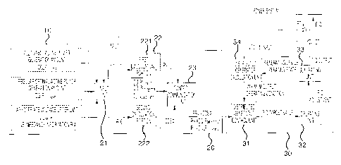
Referring to FIG. 1, an apparatus for operating a distributed generator in
connection with a power system according to one embodiment of the present
invention
includes a main control device 10, a local controller 20, and a distributed
generator 30.
The main control device 10 calculates and transmits an allowable active power
generation amount DG_Poutdimit of the distributed generator 30, a regular
optimal active
power generation amount DG_P
= out-optimal of the distributed generator 30, an admissible
voltage upper limit Vupper-limit of an interconnection line, and impedance
information R
and X of a connected distribution line to the local controller 20 of the
corresponding
distributed generator 30.
The main control device 10 described above stores power system information
such as voltage distribution and a load factor of the power system, a bus
voltage of a
substation, and an operation state of the distributed generator 30 and figures
out the
overall operation state of the power system.
Through this, the main control device 10 calculates the allowable active power
generation amount DG_Pout-iimit, calculates a voltage drop considering the
load factor of
the corresponding distribution line, and calculates the regular optimal active
power
generation amount DG_P
= out-optimal of the connected distributed generator 30. Particularly,
since the regular optimal active power generation amount DG_Pout-optimal
varies together
with a change of the load factor, the main control device 10 periodically
calculates the
regular optimal active power generation amount DG_Pout-optimai= Since the
regular
optimal active power generation amount DG_Pout-optimal is greater than the
allowable
active power generation amount DG_Pout-limit, a limitation on a generation
amount of a
power generation provider may be minimized.
The main control device 10 has to comprehensively determine such a regular
optimal active power generation amount DG_Pout_optimai considering information
such as
the load factor of the line, voltage drop distribution according thereto, and
a bus-
dispatched voltage of the substation.
11
CA 02908384 2015-09-28
Attorney Docket No. 1186P005CA01
The operation process of the main control device 10 will be described with
reference to FIG. 2.
Referring to FIG. 2, when a parameter request is made by the local controller
20,
a parameter is changed due to a system change, or a updating period for
updating the
parameter comes (S100), the main control device 10 calculates an voltage upper
limit
minimum voltage margin Vmargin-min of a point of common coupling with the
distributed
generator, the allowable active power generation amount DG_Pout-timit and the
regular
optimal active power generation amount DG_Pout-optimal of the corresponding
distributed
generator 30, the admissible voltage upper limit Vupper-limit of the
corresponding line, and
the impedance information R and X of the corresponding line (S102 to S108),
records
and updates these parameters (S110), and transmits the parameters to the local
controller 20 of the corresponding distributed generator 30 (S112).
Here, a method of calculating the allowable active power generation amount
DG_Pout_hmit and the regular optimal active power generation amount DG_Pout-
optimal of
the corresponding distributed generator 30, the admissible voltage upper limit
Vupper-limit
of the corresponding line, and the impedance information R and X of the
corresponding
line will be described below.
In addition, the main control device 10 calculates a connectable active power
maximum amount DL_Pmax which does not exceed an admissible voltage range
although being connected to any point of each distribution line for each
distribution line
and adds a gross capacity ZPDG of the distributed generator 30 connected to
each
distribution line. When the gross capacity IPDG exceeds the connectable active
power
maximum amount DL_Pmax, the allowable active power generation amount DG_Pout-
iimit
of the individual distributed generator 30 is calculated and distributed to
each distributed
generator 30.
12
CA 02908384 2015-09-28
Attorney Docket No. 1186P005CA01
Through this, when a late provider applies for additional connection of the
distributed generator 30, an host operation system allows the late provider to
receive an
active power generation rate identical to those of existing providers. Through
this, it is
possible to maintain equity among providers and to maximize a utilization rate
of
distributing facilities.
The method of calculating the allowable active power generation amount
DG_Pout-iimit and the regular optimal active power generation amount DG_Pout-
optimai of
the distributed generator 30, the admissible voltage upper limit Vupper-limit
of the
corresponding line, and the impedance information R and X of the corresponding
line
will be described.
The voltage upper limit minimum voltage margin Vmargin-min at the point of
common coupling with the distributed generator is calculated from a dispatched
voltage
margin Vdispatch-margin shown in FIG. 3.
A voltage rise margin is calculated by adding the dispatched voltage margin to
an
extra-high voltage drop portion.
Since the extra-high voltage drop portion varies according to a length of the
line
and an extra-high voltage load factor, the minimum voltage margin available
regardless
of a connection position becomes the dispatched voltage margin.
The dispatched voltage margin is calculated by subtracting a low voltage
supply
upper limit from the admissible voltage upper limit shown in FIG. 3 as shown
in following
Equation 1. The admissible voltage upper limit is a value to be obligatorily
complied
with according to a voltage management system by a power provider according to
laws
and rules. Domestically, 233 V (1.06 pu) is an example thereof.
V =margin-min dispatch-margin - V
th IV-max
S ... Equation 1
13
CA 02908384 2015-09-28
Attorney Docket No. 1186P005CA01
Here, Vmargin-min indicates a voltage upper limit minimum voltage margin,
Vdispatch-
margin indicates a dispatched voltage margin, Vupper-timit indicates an
admissible voltage
upper limit, and VLv-max indicates a low voltage supply upper limit.
The low voltage supply upper limit Vmargin-min, as shown in following Equation
2, is
calculated by subtracting a voltage drop portion caused by a transformer and a
lead-in
wire from a value obtained by converting an extra-high dispatched voltage into
a low
voltage.
The low voltage is converted by multiplying an extra-high voltage by a
transformation ratio. For example, to convert an extra-high regular voltage of
13200 V
into a low regular voltage of 220V, a transformation ratio of 13200/230 is
used. In this
case, when an extra-high voltage is 13200 V (1.0 pu), a low voltage becomes
230 V
(about 1.045 pu) higher than 220 V (1.0 pu) by 10 V. Accordingly, when an
extra-high
voltage is converted into a low voltage, it is necessary to multiply a
transformation ratio
conversion factor of 1.045.
V L17-max V I7-dispatch( V d---rop_
tr+ V drop-service)
VV
LV-dispatch ¨ X RV-dispatch Ctr
... Equation 2
Here, VLV-dispatch indicates a dispatched voltage obtained by converting into
a low
voltage, VHV-dispatch indicates an extra-high substation-dispatched voltage
(an extra-high
voltage of a secondary bus of the substation), Ct, indicates a transformation
ratio
conversion factor which transforms an extra-high voltage into a low voltage,
Vdrop-tr
indicates a voltage drop at a transformer, and Vdrop-service indicates a
voltage drop at a
lead-in wire.
14
CA 02908384 2015-09-28
Attorney Docket No. 1186P005CA01
As shown in Equations 1 and 2 and FIGS. 3 and 4, the voltage upper limit
minimum voltage margin Vmargin-min at the point of common coupling with the
distributed
generator is determined by the extra-high dispatched voltage determined by a
tap
position of a main transformer of the substation and a load factor of a
corresponding
distribution line. Since such values vary with time, the voltage upper limit
minimum
voltage margin Vmargin-min at the point of common coupling with the
distributed generator
is periodically calculated and determined.
The allowable active power generation amount DG-Paut-iimit of the connected
distributed generator 30 is calculated as follows. First, a tap change point
of a
distributing transformer to compensate a voltage drop at a terminal of an
interconnection line or an extra-high voltage line may be determined to be a
connection
check point. A maximum connectable active power aggregate amount DL_Pmax of
the
distribution line which is within an admissible voltage range at the
connection check
point is calculated. Regardless of a location of the interconnection line, the
maximum
connectable active power aggregate amount DL_Pmax should not generate a
voltage
rise at a corresponding distribution line. Accordingly, as a voltage rise
margin, a
dispatched voltage margin of FIG. 4 provided as the same value regardless of
location
is used. A voltage change which occurs when the distributed generator 30
generates
power at a random common coupling point is calculated through following
Equation 3.
S DG
%V põ=(%R = coso %X = sin) X _____________________
- S Base
... Equation 3
Here, kV'. indicates a regular voltage variation [%] at the point of common
coupling with the distributed generator, SBase indicates a reference capacity,
SIDG
indicates an installed capacity of the distributed generator 30 and is
PDG=coscp, %R
indicates a resistance component of a A line impedance calculated as the
reference
capacity from the substation to the point of common coupling with the
distributed
generator, and %X indicates a reactance component of the 'Ye line impedance
CA 02908384 2015-09-28
Attorney Docket No. 1186P005CA01
calculated as the reference capacity from the substation to the point of
common
coupling with the distributed generator.
In Equation 3, a condition in which a voltage rise becomes maximum is when the
distributed generator 30 is connected to a point where a line impedance is
greatest
while operating at a power factor of 1. Accordingly, when the distributed
generator 30 is
connected to the terminal of the line or the tap change point and operates at
the power
factor of 1, that is, when the voltage change /0\/pcc calculated using
Equation 3 does not
exceed the minimum voltage margin that is the dispatched voltage margin
(%Vdispatch-
margin=%Vmargin-min) and operates an operating condition of the power factor
of 1, the
installed capacity SDG of the distributed generator may be calculated as the
maximum
connectable active power aggregate amount DL_Pmax of the corresponding
distribution
line. A method of calculating the maximum connectable active power aggregate
amount DL_Pmax is same as following Equation 4. When the power factor is 1,
Equation
3 may be shown as following Equation 4 (cosT=1).
P DG
% v =%Rx _____________________________
pcc
S Base
%V
pcc
P DG= SBaseX _________________________
%R
... Equation 4
In Equation 4, when /oVpcc=%Vmargin-min, PDG=D1¨_Pmax= Accordingly, the
maximum connectable active power aggregate amount DL_Pmax at the
interconnection
line may be calculated as following Equation 5 (S120). Here, %R indicates a
resistance
component of a % impedance calculated using a reference capacity from a
substation
to a terminal at an interconnection line or from the substation to a tap
change point.
% Vmargin-min
DL =
P max
_ S Base X ____________
AR ... Equation 5
16
CA 02908384 2015-09-28
Attorney Docket No. 1186P005CA01
Since a terminal of an interconnection line and a distributing transformer tap
change point are points with a highest voltage rise among points of common
coupling
with the distributed generator, the maximum connectable active power aggregate
amount DL_Pmax calculated at this voltage rise occurrence point does not cause
an
overvoltage even though being connected to any point of common coupling with
the
distributed generator at the interconnection line. That is, when an aggregate
capacity of
all individual distributed generators 30 does not exceed a connectable
aggregate
amount, an overvoltage does not occur. Accordingly, an allowable active power
generation amount DG_Pout-iimit of the individual distributed generator 30, as
shown in
FIG. 5, becomes a regular output capacity PDG of the distributed generator 30
(S122
and S124). That is, even when electric power is generated with 100% of a
regular
output, an overvoltage does not occur.
On the contrary, when an aggregate capacity EPDG of all individual distributed
generators 30 exceeds the maximum connectable active power aggregate amount
DL_Pmax, the allowable active power generation amount DG_Pout-iimit of the
individual
distributed generator 30, as shown in FIG. 5, is distributed at an installed
capacity ratio
as shown in following Equation 6 (S126 and S128).
P
DG - P out-hi-rut DG
X OR
DL _ P max
OR¨ _________________________ X100
DG ... Equation 6
Here, FOG indicates a maximum active output amount of the distributed
generator
30 and is an installed capacity (=SDG/cosszP) of the distributed generator 30
when the
power factor is 1, ZPDG indicates an installed capacity aggregate of the all
distributed
generators 30 of the connected distribution line (when the power factor is 1),
and OR
indicates an allowable active output operating ratio of the corresponding
interconnection
line.
17
CA 02908384 2015-09-28
Attorney Docket No. 1186P005CA01
The regular optimal active power generation amount DG-P
= out-optimal of the
connected distributed generator 30 is calculated as follows.
The regular optimal active power generation amount DG_Pout-optimal is
calculated
by applying Equation 5, in which a minimum voltage margin is not used as a
numerator
term but a voltage rise margin shown in FIG. 4 which includes an extra-high
voltage
drop caused by a load is used.
The regular optimal active power generation amount DG_Pout-optimal has a
voltage
rise margin which differs according to a point of common coupling with the
distributed
generator, to which the individual distributed generator 30 is connected. This
is
because a load state and an extra-high voltage drop according thereto differ.
The
regular optimal active power generation amount DG_Pout-optimal is calculated
through
following Equation 7 formed by modifying Equation 5 described above.
X _____________________
% dispatch-margin+% V drop-load
DG - Pout-optimal¨ S Base A CAR ... Equation 7
Here, a value of %R indicates a resistance component of a A line impedance
from the substation to the individual distributed generator 30.
Line impedances R and X at the point of common coupling is calculated by
adding line impedance data for respective sections from the point of common
coupling
with the distributed generator to a bus of the substation.
The line impedance data for the respective sections are recorded and managed
in a database (not shown) of a power system operating system, in which both a
calculated value and an actual measurement value are used, thereby recording
and
managing data having high accuracy in the database.
18
CA 02908384 2015-09-28
Attorney Docket No. 1186P005CA01
The calculated value is generally used for a present distribution line, and
the
actual measurement value is generally used for a transmission line. A method
of
calculating the line impedance to the point of common coupling with the
distributed
generator is as follows.
First, when the point of common coupling with the distributed generator is
determined, line impedances for the respective sections are obtained by
multiplying %
impedance data per km according to line types of the respective sections by
section
lengths, the line impedances for the respective sections from the substation
to the point
of common coupling with the distributed generator are added, and the
aggregated line
impedances are divided into resistance components and reactance components,
thereby calculating the line impedances to the point of common coupling with
the
distributed generator.
The main control device 10 records all the parameters calculated described
above in the database and transmit the parameters to the local controller 20.
The local controller 20 calculates an operating power factor instruction value
PFset and an active output instruction value Pset using the parameters
transmitted from
the main control device 10 and a voltage V(t) and a current 1(t) presently
measured at
the point of common coupling with the distributed generator and selectively
determines
and transmits the operating power factor instruction value PFset and the
active output
instruction value Pset to the distributed generator 30.
As shown in FIG. 1, the local controller 20 includes an input unit 21 which
receives and stores the parameters transmitted from the main control device 10
of the
power system operating system and the voltage and current measured at the
point of
common coupling with the distributed generator, a calculation unit 22 which
calculates
new parameters from the parameters transmitted form the main control device 10
and
the voltage and current measured at the point of common coupling with the
distributed
19
CA 02908384 2015-09-28
Attorney Docket No. 1186P005CA01
generator, and a control communication unit 23 which finally selects and
transmits an
appropriate parameter considering data which reflects a power system operating
state.
Hereinafter, an operation process of the local controller 20 will be described
with
reference to FIG. 6.
Referring to FIG. 6, first, the input unit 21 stores and updates the
parameters
transmitted from the main control device 10 (S200) and receives the voltage
and current
at the point of common coupling with the distributed generator (S202).
After that, a first calculation portion 221 calculates instantaneous output
active
power using following Equation 8 (S204).
P DG(t) t) COS 0( t)
... Equation 8
After that, the control communication unit 23 compares and determines whether
the presently measured voltage V(t) exceeds an admissible voltage upper limit
Vupper-limit
transmitted from the main control device 10 (S206).
Here, when the measured voltage value exceeds the admissible voltage upper
limit, the distributed generator 30 reduces an active output to restrain a
voltage rise.
Accordingly, the control communication unit 23 sets the active output limit
value of the
distributed generator 30 as an allowable active power generation amount
DG_Pout-hmit of
the connected distributed generator 30 calculated at the main control device
10 (S208)
and transmits the active output limit value Pset to the distributed generator
30 (S210).
Since the active output limit value Pset is a generation amount which does not
cause an
overvoltage even though being connected to any point of a corresponding
distribution
line, the distributed generator 30 with a voltage at the point of common
coupling with the
distributed generator, which exceeds the admissible voltage upper limit, is
all set as the
active power limit value by the local controller 20.
CA 02908384 2015-09-28
Attorney Docket No. 1186P005CA01
When transmission of the active power limit value Pset is completed, the
control
communication unit 23 checks whether the parameters are received (S224), and
depending on a result thereof, returns to the operation S200 to update the
parameters
or measures and inputs the voltage and current.
Meanwhile, as a result of the operation 206 in which whether the measured
voltage V(t) exceeds the admissible voltage upper limit Vupper-iimit
transmitted from the
main control device 10, when the presently measured voltage is the allowable
admissible voltage upper limit Vupper_limit or less, the active output limit
value Pset of the
distributed generator 30 is set as a preset first set value (default) (S212)
and it is
determined whether a present instantaneous active power output amount PDG(t)
exceeds the regular optimal active power generation amount DG-Pout-optimai of
the
distributed generator 30 (S214) to determine the operating power factor
instruction
value PFset.
That is, when the instantaneous active power output amount is the regular
optimal active power generation amount of the connected distributed generator
30 or
less, the control communication unit 23 determines the operating power factor
instruction value PF,et to be a second set value (default) (S216).
However, when the instantaneous active power output amount is more than the
regular optimal active power output amount, an overvoltage may occur at the
point of
common coupling with the distributed generator. Accordingly, the control
communication unit 23 calculates and determines the operating power factor
instruction
value to prevent voltage fluctuations from occurring at the point of common
coupling
with the distributed generator through a second calculation portion 222 (S218
and
S220).
Here, a process in which the second calculation portion 222 calculates the
operating power factor instruction value of the distributed generator 30 is as
follows.
21
CA 02908384 2015-09-28
Attorney Docket No. 1186P005CA01
First, a regular voltage fluctuation rate at the point of common coupling with
the
distributed generator is calculated. When the distributed generator 30 is
connected to a
distribution system and operates at a leading phase power factor (a lagging
phase
power factor based on power system), the regular voltage fluctuation rate at
the point of
common coupling with the distributed generator is calculated through following
Equation
9.
SDG(R COSM-X sinl(H)
A V¨
PC e , V 2
I
... Equation 9
Here, AVpcc indicates a voltage fluctuation rate at the point of common
coupling
with the distributed generator, SDG indicates a capacity MVA of the
distributed generator
30, R indicates a normal resistance component of a distribution line, X
indicates a
normal reactance component of the distribution line, cD indicates a power
factor angle of
the distributed generator 30, COS II indicates an operating power factor of
the
distributed generator 30, and VL indicates a nominal voltage of the
distribution line.
As shown in Equation 9 described above, to minimize the voltage fluctuation
rate
AVpcc at the point of common coupling with the distributed generator, a
numerator in
Equation 9 has to be '0'.
Also, since relationships among apparent power SDG, active power PDG, and
PDG AS'DG COS
reactive power QDG of the distributed generator 30 are
and
DG S DG sin I (I) I
, Equation 9 may be developed as following Equation 10.
SDAR
cos-X' m1(0=0
22
CA 02908384 2015-09-28
Attorney Docket No. 1186P005CA01
SDGCOSIO1 .R-SDGsinlol .X=0
P DG R= DG X
... Equation 10
Here, Equation 10 indicates that there is no voltage fluctuation at the point
of
common coupling with the distributed generator when a voltage rise portion
obtained by
multiplying an active output of the distributed generator 30 by a resistance
component
of the line and a voltage drop portion obtained by multiplying a reactive
output of the
distributed generator 30 by a reactance component of the line are identical to
and
compensated with each other.
Equation 10 described above is arranged as following Equation 11.
P DG
tan I 11) I -
DG X
P DG X
COSM- _____________
2 2
P DG2 DG R21-X
... Equation 11
Here, referring to Equation 11, it may be known that a voltage fluctuation
rate
becomes 0% when a distributed generator operating power factor is identical to
an
X
interaction formula R2 X2 between a
normal resistance component and a normal
reactance component of the distribution line.
That is, an operating power factor connection condition of the distributed
generator 30 with the voltage fluctuation rate of 0% at the point of common
coupling
with the distributed generator regardless of a capacity for connecting of the
distributed
23
CA 02908384 2015-09-28
Attorney Docket No. 1186P005CA01
generator 30 is determined by an impedance ratio of the distribution line.
Actually,
since several wires are used for the distribution line in combination, it is
necessary to
apply combined impedances from a point of common coupling with the distributed
generator to a substation for each wire.
Following Table 1 shows wire types of aerial distribution line, corresponding
impedance information thereof, and operating power factor calculation values
of the
distributed generator 30 theoretically calculated to minimize a voltage
fluctuation rate
using Equation 11.
[Table 1]
Wire Types of Aerial Distribution Line and Corresponding Impedance Information
Wire type of R(')/o/km) X( /0/km) Operating power
Distribution line factor (calculated
value) for
minimizing
voltage
fluctuation rate
ACSR 58 (mm2) 9.48 8.3686 0.651
ACSR 95 (mm2) 5.9739 8.0851 0.804
ACSR 160 (mm2) 3.4999 7.7498 0.911
ACSR 240 (mm2) 2.3604 7.4538 0.953
Meanwhile, when an active output limit value Pset and an operating power
factor
instruction value PF,et set as described above are determined, the control
communication unit 23 transmits the active output limit value Pset and the
operating
power factor instruction value PFset to the distributed generator 30 (S222).
After that, when transmission of parameters to the distributed generator 30 is
completed, the control communication unit 23 determines whether the main
control
device 10 receives a new parameter (S224) and returns to the operation S200 to
update
24
CA 02908384 2015-09-28
Attorney Docket No. 1186P005CA01
the parameter or returns to the operation S202 to receive a voltage and
current
depending on a result of the determination.
At last, when there is no input from the local controller 20, the distributed
generator 30 autonomously calculates a maximum output operating condition and
determines an active power target value and a reactive power target value to
operate.
When an input of new parameters, that is, an operating power factor
instruction
value PFset and an active output instruction value Pset are input, the
distributed
generator 30 determines generation output target values P and Q of active
power and
reactive power according to a predetermined operating mode using the received
operation power factor instruction value PFset and the active output
instruction value Pset.
The distributed generator 30 described above, as shown in FIG. 1, includes a
distributed generator control unit 31, an operating unit 32, a generating unit
33, and a
distributed generator calculation unit 34.
The distributed generator control unit 31 controls overall the distributed
generator
30. When parameters, for example, an operating power factor instruction value
PFset
and an active output instruction value Pset are received from the local
controller 20, the
distributed generator control unit 31 updates the parameters and calculates
optimal
operating conditions for a maximum generation output of the distributed
generator 30,
that is, an active power target value P and a reactive power target value Q to
operate.
The operating unit 32 adjusts the active power target value P and the reactive
power target value Q received from the distributed generator control unit 31
and inputs
the adjusted active power target value P and reactive power target value Q to
the
generating unit 33.
Accordingly, the generating unit 33 generates according to the active power
target value P and the reactive power target value Q adjusted by the operating
unit 32
and outputs active power P and reactive power Q.
CA 02908384 2015-09-28
Attorney Docket No. 1186P005CA01
The distributed generator calculation unit 34 monitors the active power P and
the
reactive power Q of the generating unit 33 and inputs maximum output operating
conditions according to an operating state to the distributed generator
control unit 31.
The operation process of the distributed generator 30 will be described in
detail
with reference to FIG. 7.
Referring to FIG. 7, the distributed generator control unit 31 updates
parameters
transmitted from the local controller 20 (S300).
The distributed generator control unit 31 updates the parameters transmitted
from the local controller 20 in an internal memory (not shown) and calculates
optimal
operating conditions for a maximum generation output to operate (S302). This
is
performed according to a basic function of the distributed generator 30.
After that, the distributed generator control unit 31 determines whether the
parameters input from the local controller 20, that is, an active output
instruction value
Pset and an operating power factor instruction value PFs.t are a first set
value and a
second set value, respectively, (S304 and S308). When the active output
instruction
value Pset and the operating power factor instruction value PFõt are the first
set value
and the second set value, respectively, the distributed generator control unit
31
operates the distributed generator 30 with the optimal operating condition
calculated in
the operation S302 (S314).
Meanwhile, as a result of the determination in the operation S304, when the
active output instruction value Pset is not set as the first set value but set
as an allowable
active power generation amount DG_Pout-iimit of the individual distributed
generator 30,
the distributed generator control unit 31 operates while limiting an active
output to the
allowable active power generation amount DG_Pout-limit (S306).
26
CA 02908384 2015-09-28
Attorney Docket No. 1186P005CA01
Here, when the active output instruction value Pset is not set as the first
set value
but set as the allowable active power generation amount DG_Pout_limit of the
individual
distributed generator 30, an overvoltage may occur when the distributed
generator 30 is
continuously operating with a present instantaneous output.
On the other hand, in a state in which the active output instruction value
Pset is
set as the first set value, when the operating power factor instruction value
PFset is not
set as the second set value but set as an operating power factor instruction
value PFset
calculated at the second calculation portion 222 as a result of the
determination in the
operation S308, the distributed generator control unit 31 determines whether
the
generating unit 33 of the distributed generator 30 is able to operate with the
operating
power factor instruction value PFset calculated at the second calculation
portion 222
considering operating environments such as present active output intensity and
an
autonomous reactive power generation ability of the distributed generator 30
(S310).
As a result of the operation S310, when it is impossible to operate with the
operating power factor instruction value PFset, the distributed generator
control unit 31
abandons a fixed power factor operating mode, converts into an active output
limit
mode, and operates not to exceed the allowable active power generation amount
DG_Pout-iimit of the individual distributed generator 30 (S306).
However, as the result of the determination in the operation S310, when it is
possible to operate with the set operating power factor instruction value
PFset, the
distributed generator control unit 31 converts into the fixed power factor
operating mode
and operates with a set operating power factor (S312). Since an overvoltage
does not
occur at the point of common coupling with the distributed generator in all
cases, while
operating, the distributed generator control unit 31 determines whether
parameters are
received from the local controller 20 (S316), and depending on a result of the
determination thereof, updates new parameters (S300) or returns to the
operation S302.
27
CA 02908384 2015-09-28
Attorney Docket No. 1186P005CA01
Through this, while respective providers minimize losses of generation
amounts,
a large number of providers may generate power sharing a distribution line and
a
utilization rate of facilities of the distribution line may be maximized.
Hereinafter, a result of simulating the apparatus for operating the
distributed
generator in connection with the power system according to one embodiment of
the
present invention using a distribution line model of FIG. 8 will be described.
FIG. 8 is a view illustrating an example of a model power distribution system
according to one embodiment of the present invention. FIG. 9 is a view
illustrating a
result of analyzing a model system simulation under a heavy-load condition (10
MVA
and 1.0 pu) according to one embodiment of the present invention. FIG. 10 is a
view
illustrating voltage distribution in a distribution line for each distributed
generator power
factor under the heavy-load condition (10 MVA and 1.0 pu) according to one
embodiment of the present invention. FIG. 11 is a view illustrating a result
of analyzing
a model system simulation under a light-load condition (2.5 MVA and 0.25 pu)
according to one embodiment of the present invention. FIG. 12 is a view
illustrating
voltage distribution in a distribution line for each power factor of the
distributed
generator under a light-load condition (2.5 MVA and 0.25 pu) according to one
embodiment of the present invention.
The result of changing a power factor condition of the distributed generator
30 of
the distribution line model shown in FIG. 8 and analyzing the voltage
distribution in the
heavy-load state is shown in FIGS. 9 and 10. The result of analyzing in the
light-load
condition is shown in FIGS. 11 and 12.
Referring to FIGS. 9 to 12, there is no difference in voltage fluctuation
rates in
results of analyzing Case1 and Case2. Also, it may be known that there is
barely a
difference in voltage fluctuation rates at distributed generators DG1 and DG2.
Accordingly, it may be known from the two analysis results that the same
voltage
28
CA 02908384 2015-09-28
Attorney Docket No. 1186P005CA01
distribution is shown regardless of a level of load and a capacity of the
distributed
generator 30.
Casel is a voltage distribution state in which there is no output of the
distributed
generator 30, that is, a state before the distributed generator 30 is
connected to the
distribution line. Case2 is a state in which DG1 and DG2 are connected to the
distribution line and generate with regular outputs, respectively.
Here, the respective distributed generators 30 operate with the power factor
calculated using Equation 11. Case4 is a condition of operating with a power
factor of 1.
Case3 is a state to which a power factor condition between a power factor
condition of
Case2 and a power factor condition of Case4 is applied.
As shown in the result of analysis, it may be known that the power factor of
the
distributed generator 30 determined through Equation 11 provided to minimize a
voltage
fluctuation rate based on impedance properties of the distribution line and a
voltage rise
theory of a distribution system fundamentally minimizes a voltage fluctuation
rate at the
distribution system, thereby maximizing a capacity for connecting the
distributed
generator 30 to the distribution line.
FIG. 13 is a block diagram illustrating an example of the apparatus for
operating
the distributed generator in connection with the power system according to one
embodiment of the present invention. FIG. 14 is a block diagram illustrating
another
example of the apparatus for operating the distributed generator in connection
with the
power system according to one embodiment of the present invention. FIG. 15 is
a block
diagram illustrating still another example of the apparatus for operating the
distributed
generator in connection with the power system according to one embodiment of
the
present invention. FIG. 16 is a block diagram illustrating yet another example
of the
apparatus for operating the distributed generator in connection with the power
system
according to one embodiment of the present invention.
29
CA 02908384 2015-09-28
Attorney Docket No. 1186P005CA01
In the embodiment described above, as shown in FIG. 13, the local controller
20
is separately configured from the distributed generator 30.
However, the technical scope of the present invention is not limited thereto.
The
local controller 20 may be variously installed inside or outside the
distributed generator
30 depending on a generation amount of the distributed generator 30 and
communication infrastructures.
Referring to FIG. 14, the local controller 20 may be installed inside the
distributed
generator 30 while being integrated with the distributed generator 30. In this
case,
related parameters are transmitted from the main control device 10 of the
power system
operating system that is an upper operating system to operate in connection.
In addition, the local controller 20 may operate being locally optimized
without
being connected to the upper operating system. In this case, since costs for
communication infrastructures may be reduced, it is appropriate for conditions
not
equipped with communication infrastructures.
Also, when the local controller 20 is configured to be embedded in the
distributed
generator 30, it is possible to directly receive parameters from the main
control device
10 of the power system operating system. When a plurality of such distributed
generators 30 are installed and the power system operating system integrally
manages
the plurality of distributed generators 30, it is possible to obtain the same
effects even
when the local controller 20 is built in the main control device 10.
Additionally, it is necessary to operate only with a locally optimized
solution,
without connection with the power system operating system. That is, in a place
with
poor information communication infrastructures like a line in rural areas with
low-level-
loads unlike a downtown area lined with loads in a place connected with
distributed
generator, as shown in FIGS. 15 and 16, the local controller 20 may be
separately
configured from the main control device 10 or may be built in the distributed
generator
CA 02908384 2015-09-28
Attorney Docket No. 1186P005CA01
30. In this case, it is applicable without support of information
communication
infrastructures, thereby being directly applied to a present operating
condition.
While one or more embodiments of the present invention have been described
with reference to the figures, which are merely examples, it will be
understood by those
of ordinary skill in the art that various changes in form and details may be
made therein.
Therefore, the substantial technical protection scope of the present invention
should be determined according to the following claims.
31