Note : Les descriptions sont présentées dans la langue officielle dans laquelle elles ont été soumises.
CA 02908460 2016-03-30
1
SPECIFICATION
Title of Invention: NON-CONTACT POWER SUPPLY SYSTEM AND POWER
SUPPLY DEVICE
Technological Field
[0001] The present invention relates to a non-contact power supply system
and a
power supply device.
[0002]
Background Art
[0003] A power supply system of an electric vehicle that supplies power in
a non-
contact manner from a power supply device provided on the ground to an
electric vehicle,
in which a vehicle detection unit for determining whether or not the electric
vehicle has
entered a chargeable area is provided in the power supply device, and
communication is
established with the electric vehicle and the power supply device by wireless
communication after the sensor detects that the electric vehicle has entered a
chargeable
area, to supply power from a power supply unit of the power supply device to a
power
reception unit of the electric vehicle has been disclosed.
Prior Art Documents
Patent Documents
[0004] Patent Document 1: International Publication No. 2012-42902
Disclosure of the Invention
[0005] However, in the system described above, the system of the power
supply
device is not activated until after the vehicle enters a chargeable area; as a
result, there is
a problem that the user cannot grasp the state of the power supply device
before parking
the vehicle in the chargeable area.
CA 02908460 2016-03-30
2
[0006] A goal of the present invention is to provide a power supply device
or a non-
contact power supply system in which the user can grasp the state of the power
supply
device before parking the vehicle in a chargeable area.
[0007] The present invention addresses this goal by receiving a startup
signal for
activating a power supply device by wireless communication, detecting the
possible state
of non-contact power supply which represents a state in which power can be
supplied in a
non-contact manner from a power transmission coil, causing a notification
means to make
a notification in a first notification state when detecting a non-contact
power supply
possible state, and setting the notification state of the notification means
to a state that is
different from the first notification state described above, when not
detecting a non-
contact power supply possible state.
According to an aspect of the present invention there is provided a power
supply device that supplies power from a power transmission coil to a power
reception
coil that is provided to a vehicle in a non-contact manner by means of at
least a magnetic
coupling, comprising:
a communication means that receives a startup signal for activating the power
supply device from the vehicle that is running by wireless communication;
a notification means for notifying a state of the power supply device;
a detection means for detecting the state of the power supply device based on
the startup signal; and
a control means for controlling the notification means based on a detection
result of the detection means; wherein
the detection means
detects a non-contact power supply possible state, which represents a state in
which the power can be supplied from the power transmission coil in a non-
contact
manner,
the control means
sets a notification state of the notification means to a first notification
state,
when the detection means detects the non-contact power supply possible state,
and
sets the notification state of the notification means to a state that is
different
from the first notification state, when the detection means is not detecting
the non-contact
power supply possible state.
CA 02908460 2016-03-30
2a
According to another aspect of the present invention there is provided a non-
contact power supply system that supplies power between a power reception coil
that is
provided to a vehicle and a power transmission coil that is provided to a
power supply
device in a non-contact manner by means of at least a magnetic coupling,
wherein
the vehicle comprises:
a communication means that receives a startup signal for activating the power
supply device from the vehicle that is running by wireless communication;
a notification means for notifying a state of the power supply device; and
a vehicle side control means for controlling the communication means and
the notification means,
the power supply device comprises:
a power supply device side communication means for receiving the startup
signal;
a detection means for detecting the state of the power supply device based on
the startup signal; and
a power supply device side control means for transmitting a signal containing
the detection result of the detection means by controlling the power supply
device side
communication means; and
the detection means
detects a non-contact power supply possible state, which represents a state in
which power can be supplied from the power transmission coil in a non-contact
manner,
the vehicle side control means
sets a notification state of the notification means to a first notification
state,
when the detection means detects the non-contact power supply possible state,
and
sets the notification state of the notification means to a state that is
different
from the first notification state, when the detection means is not detecting
the non-contact
power supply possible state.
[0008] Since the state of the power supply device is notified after
activating the
power supply device by wireless communication, the present invention achieves
the
effect that the user can grasp the state of the power supply device before
parking the
vehicle in a chargeable area.
CA 02908460 2016-03-30
2b
Brief Description of the Drawings
[0009] [FIG. 1] Block view of a non-contact power supply system according
to an
embodiment of the present invention.
[FIG. 2] Block view of the vehicle side controller and the power supply
device side controller in FIG. 1.
[FIG. 3] Plan view for explaining the positional relationships of a plurality
of
vehicles, and a plurality of parking spaces each provided with a power supply
device.
[FIG. 4] Schematic view of a power pattern list that is generated on the
vehicle side in FIG. 1.
[FIG. 5] Flowchart illustrating the control flow of the vehicle side
controller
and the power supply device side controller in FIG. 1.
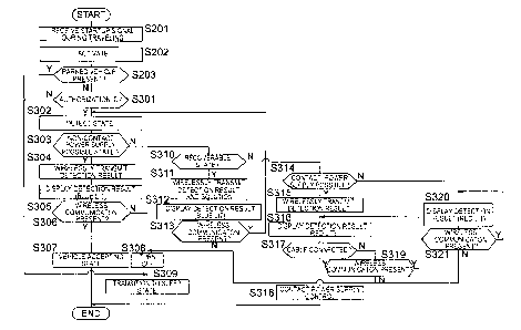
[FIG. 6] Flow chart illustrating the control flow of step S100 in FIG. 5.
[FIG. 7] Flow chart illustrating the specific control flow of step S200 and
step S300 in FIG. 5.
[FIG. 8] Flow chart illustrating the specific control flow of step S400 in
FIG. 5.
CA 02908460 2015-09-29
3
[FIG. 9] Flow chart illustrating the specific control flow of step S500 and
the control
flow of the power supply device side, among the controls of step S600, in FIG.
5.
[FIG. 10] Flow chart illustrating the control flow of the vehicle side, among
the
controls of step S600, in FIG. 5.
[FIG. 11] Flow chart illustrating the specific control flow of step S700 and
the
control flow of the vehicle side, among the controls of step S800, in FIG. 5.
[FIG. 12] Flow chart illustrating the control flow of the power supply device
side,
among the controls of step S800, in FIG. 5.
[FIG. 13] Flow chart illustrating the specific control flow of step S100 in
FIG. 5,
which is the control procedure of the controller in a stopped vehicle.
[FIG. 14] Flow chart illustrating the specific control flow of step S110 in
FIG. 6.
Preferred Embodiments of the Invention
[0010] Embodiments of the present invention will be explained below based
on the
drawings.
[0011] <<Embodiment 1>>
FIG. 1 is a block view of a non-contact power supply system according to an
embodiment of the present invention. The non-contact power supply system of
the present
embodiment supplies power in a non-contact manner from a power transmission
coil of a power
supply device provided on the ground side to a power reception coil on the
vehicle side, by
means of at least a magnetic coupling. The system then charges the battery of
the vehicle by the
power that is received by the power reception coil. The non-contact power
supply system is a
system that is capable of charging by two systems: a system according to non-
contact power
supply and a system according to contact power supply. In a contact power
supply system
method, a charging cable is connected between a power supply device and a
charging port of a
vehicle.
[0012] Non-contact power supply systems are provided to parking facilities
such as parking
spaces of homes and shared facilities such as a parking space along a highway.
A non-contact
power supply system comprises a vehicle 2 and a power supply device 1. The
power supply
device 1 is provided to a parking space for parking a vehicle 2, and is a
ground side unit that
supplies power by non-contact power supply between coils, when the vehicle 2
is parked in a
predetermined parking position. The vehicle 2 is a vehicle 2, such as an
electric vehicle or a
CA 02908460 2015-09-29
4
plug-in hybrid vehicle, which is capable of charging a battery that is
provided in the vehicle by
an external power source.
[0013] The configuration of the power supply device 1 and the vehicle 2,
which configure
the non-contact power supply system, will be described below. In the present
embodiment, a
description will be given of an electric vehicle as the vehicle 2. In FIG. 1,
the dotted arrows
represent respective signal lines between controllers 10 and 20, and the
configuration inside the
power supply device 1 and the configuration inside the vehicle 2, while the
thick lines represent
power lines when charging a battery 24 with the power of an AC power source 3,
representing
power lines of a contact power supply system and power lines of a non-contact
power supply
system.
[0014] The power supply device 1 comprises a controller 10, a power
transmission coil 11,
a sensor 12, a power unit 13, a self-diagnosis circuit 14, a memory 15, a
wireless communication
unit 16, a display unit 17, and a relay switch 18.
[0015] The controller 10 is a main controller for controlling the entire
power supply device
1. The configuration of the controller 10 will be described below.
[0016] The power transmission coil 11 is a parallel circular shaped coil
for supplying power
in a non-contact manner to a power reception coil 21, which is provided on the
vehicle 2 side,
and is provided in a parking space in which is provided the non-contact power
supply device of
the present embodiment. The sensor 12 is a sensor for detecting the relative
position of the
power reception coil 21 with respect to the power transmission coil 11, and is
configured by, for
example, an image sensor or an infrared sensor of a camera. The detection
values of the sensor
12 are outputted to the controller 10.
[0017] The power unit 13 is a circuit for converting the AC power that is
transmitted from
an AC power source 3 to a high frequency AC power and transmitting the same to
the power
transmission coil 11, comprising a rectifier, a power factor correction
circuit (PFC (Power Factor
Correction) circuit), an inverter, and a sensor for detecting the output value
to the power
transmission coil 11. The power unit 13 outputs the desired power to the power
transmission
coil 11 by having a switching element provided to the inverter PWM-controlled
by the controller
10.
[0018] The self-diagnosis circuit 14 is a circuit for diagnosing
abnormalities such as a
ground fault of the non-contact power supply system including the wiring from
the power unit 13
CA 02908460 2015-09-29
and the AC power source 3 to the power transmission coil 11, a disconnection
in the wiring, a
detection failure of the sensor 12, and a ground fault of the contact power
supply system. The
diagnosis results of the self-diagnosis circuit 14 are outputted to the
controller 10.
[0019] The memory 15 is a recording medium for recording identification
information (ID)
that is provided to each power supply device 1 in advance, and information
that is transmitted
from the vehicle 2 side. The wireless communication unit 16 is a transceiver
that performs
bidirectional communication with a wireless communication unit 26 that is
provided on the
vehicle 2 side. A frequency that is different from the frequency that is used
in vehicle
peripherals, such as intelligence keys, is set as the communication frequency
between the
wireless communication unit 16 and the wireless communication unit 26 so that
vehicle
peripherals are less susceptible to interference by the communication even if
communication is
performed between the wireless communication unit 16 and the wireless
communication unit 26.
For example, various wireless LAN systems are used for the communication
between the
wireless communication unit 16 and the wireless communication unit 26.
[0020] The display unit 17 is a display device for notifying the state of
the power supply
device 1 to the outside, and is configured from a lamp or a display, etc. The
relay switch 18 is
provided to the wiring that configures the contact power supply system, and is
a switch for
switching between ON and OFF based on the control of the controller 10. When
charging the
battery by contact power supply, the relay switch 18 is turned ON.
[0021] The configuration of the vehicle 2 is described next. The vehicle 2
comprises a
controller 20, a power reception coil 21, a sensor 22, a power reception
circuit 23, a battery 24, a
display 25, a wireless communication unit 26, a camera 27, a GPS 28, a memory
29, a parking
confirmation button 31, a charging port 32, a charger 33, and a park lock
mechanism 34.
[0022] The controller 20 is not limited to the charging control when
charging the battery 24,
and performs various controls in the EV system of a vehicle.
[0023] The power reception coil 21 is provided on the bottom surface
(chassis), etc., of the
vehicle 2 between the rear wheels. Then, when the vehicle 2 is parked in a
predetermined
parking position, the power reception coil 21 is positioned above the power
transmission coil 11,
while maintaining the distance from the power transmission coil 11. The power
reception coil 21
is a circular shape coil that is parallel to the surface of the parking space.
CA 02908460 2015-09-29
6
[0024] The sensor 22 is a sensor for detecting the current and the voltage
that is outputted
from the power reception coil 21 to the battery 24. The detection value of the
sensor 22 is
outputted to the controller 20. The power reception circuit 23 is connected
between the power
reception coil 21 and the battery 24, and comprises a circuit and a relay
switch for converting the
AC power that is received by the power reception coil to DC power. The relay
switch switches
between ON and OFF based on a control of the controller 20. When charging the
battery 24 by a
non-contact power supply, the relay switch is turned ON.
[0025] The battery 24 is a secondary battery that outputs, via an inverter
that is not
diagrammed, power to a motor (not shown), which is the power source of the
vehicle 2. The
battery 24 is configured by connecting a plurality of secondary batteries such
as lithium-ion
batteries in series or in parallel. The battery 24 is electrically connected
to the power reception
coil 21 via the relay switch of the power reception circuit 23. The battery 24
is connected to the
charger 33.
[0026] The display 25 is, for example, provided to an instrument panel of
the vehicle 2, and
displays a map in a navigation system and a captured image or the like of a
camera 27 in a
parking assist system. The display 25 also displays the state of the power
supply device 1 and
the position of the power supply device 1 on the map. The display 25 also
displays a guide
screen for charging, when charging the battery 24 with the power supply device
1.
[0027] The wireless communication unit 26 is a communication transceiver
for performing
wireless communication with the wireless communication unit 16 on the power
supply device 1
side. The camera 27 is an imaging device for capturing the surroundings of the
vehicle. The
camera 27 is provided in the vehicle 2 in a position capable of capturing the
surroundings of the
vehicle 2. There may be a plurality of cameras 27.
[0028] The GPS 28 (Global Positioning System) is a system for measuring the
current
position of the vehicle 2, using a receiver for receiving signals from a
satellite. The memory 29
is a recording medium for recording identification information (ID) that is
provided to each
vehicle in advance, and information that is transmitted from the power supply
device 1 side. The
parking confirmation button 31 is a button for confirming that the driver has
the intention to
park, and is a switch for starting the parking assist system by an operation
of the user. The
parking confirmation button 31 is provided to the instrument panel.
CA 02908460 2015-09-29
7
[0029] The charging port 32 is a terminal for connecting a plug of a
charging cable. When
charging the battery 24 by a contact power supply, the charging cable that is
connected to the
power supply device 1 is connected to the charging port 32.
[0030] The charger 33 is a conversion circuit for converting the power that
is outputted
from the power supply device 1 via the charging port 32 and the charging cable
to DC power,
and comprises an inverter, a rectifier, and a smoothing circuit, etc. The
controller 20 converts
the AC power that is outputted from the power supply device 1 to a power that
is suitable for
charging the battery 24 by controlling the switching element included in the
inverter, based on
the charging state of the battery 24 (SOC: State of Charge), and supplies the
same to the battery
24. The charging state of the battery 24 is calculated based on a value of the
voltage or the
current of the battery 24 detected by a detection sensor (not shown) connected
to the battery 24.
[0031] The park lock mechanism 34 is a mechanical mechanism for fixing the
rotation of
the wheels, such as an emergency brake or a parking rod.
[0032] The configuration of the power supply device 1 side controller 10
and the
configuration of the vehicle 2 side controller 20 will be described next,
using FIG. 1 and FIG. 2.
[0033] The controller 10 comprises a parked vehicle determination unit 101,
a state
detection unit 102, a coil position detection unit 103, and a non-contact
power supply control
unit 104.
[0034] The parked vehicle determination unit 101 is a control unit for
determining whether
or not a vehicle is stopped in a parking space of the power supply device 1,
based on the
detection value of the sensor 12. The controller 10 makes the control when the
vehicle is
stopped in a parking space and the control when the vehicle is not stopped in
a parking space,
different controls, as described below. Accordingly, the parked vehicle
determination unit 101
determines whether or not a vehicle is parked in a parking space, in order to
determine with
which control flow the controller 10 controls the power supply device 1.
[0035] The state detection unit 102 detects the state of the power supply
device 1, based on
the detection value of the sensor 12 and the diagnostic results of the self-
diagnosis circuit 14.
The states of the power supply device 1 include: a non-contact power supply
possible state in
which non-contact power supply can be performed normally; a recoverable state
in which, even
if there is some kind of abnormality, the abnormality or the problem can be
removed by the user
of the vehicle 2; a contact power supply possible state in which only charging
by contact power
CA 02908460 2015-09-29
8
supply is possible; and a power supply disabled state representing a state in
which charging
cannot be performed by either non-contact power supply or contact power
supply.
[0036] When there is no abnormality in the circuit, etc., inside of the
power supply device 1
according to the self-diagnosis circuit 14, and there is no foreign object on
the power
transmission coil 11 according to the detection value of the sensor 12, the
state detection unit 102
detects the state to be a state in which power can be supplied from the power
transmission coil 11
to the power reception coil 21 in a non-contact manner; that is, to be the non-
contact power
supply possible state.
[0037] The state detection unit 102 determines whether or not there is a
foreign object on
the power transmission coil 11 by analyzing a captured image on the power
transmission coil 11
obtained from the sensor 12. When there is a metallic foreign object on the
power transmission
coil 11, such as an empty can, there are cases in which the magnetic flux that
is outputted from
the power transmission coil 11 is affected by the foreign object during the
non-contact power
supply, and the coupling between the coils becomes poor. On the other hand,
the foreign object
on the power transmission coil 11 can be easily removed by the user of the
vehicle.
Accordingly, the state detection unit 102 detects a state, in which the user
is able to recover from
a state in which power cannot be supplied in a non-contact manner to a non-
contact power
supply possible state, i.e., a recoverable state, if the power supply device 1
is detected to be
normal by the self-diagnosis circuit 14 and a foreign object is detected on
the power transmission
coil 11 by the sensor 12.
[0038] In addition, the state detection unit 102 also determines the state
to be the
recoverable state described above when the self-diagnosis circuit 14 detects
that the cable of the
power supply device 1 is detached from the AC power source 3. If the power
supply device 1 is
configured so that the user is able to connect the cable of the power supply
device 1 to an AC
power source 3, said cable detachment is also a problem that can be removed by
the user. A
cable detachment can be detected by the self-diagnosis circuit 14 by detecting
an impedance
change or a potential difference caused by the presence/absence of a cable
connection.
Accordingly, the state detection unit 102 detects a recoverable state based on
the diagnostic
results of the self-diagnosis circuit 14.
[0039] The recoverable state is not limited to a problem due to a foreign
object on the power
transmission coil 11 or due to a cable not being connected to the AC power
source 3, and may be
CA 02908460 2015-09-29
9
a state in which there are other flaws or problems that can be solved by the
user. An example is
when the system is temporarily shut down for maintenance of the non-contact
power supply
system and charging by the non-contact power supply cannot be performed
immediately even
when the user parks in a parking space, but charging can be performed after
completion of the
maintenance. In such a case, a user is able to solve the problem of not being
able to perform
non-contact charging by setting a timer in accordance with the completion time
of the
maintenance. Accordingly, the state detection unit 102 may also determine such
a state to be a
recoverable state.
[0040] Additionally, the state detection unit 102 also diagnoses
abnormalities in the
charging circuit according to the contact power supply with the self-diagnosis
circuit 14.
Accordingly, the state detection unit 102 detects the state to be a contact
power supply possible
state, when the non-contact power supply cannot be performed and when only
charging by a
contact power supply is possible. In addition, the state detection unit 102
detects the state to be a
power supply disabled state when neither a non-contact power supply nor a
contact power supply
can be performed, and when not in a recoverable state.
[0041] The coil position detection unit 103 detects the relative position
of the power
reception coil 21 with respect to the power transmission coil 11 using the
sensor 12.
[0042] The non-contact power supply control unit 104 outputs the power of
the AC power
source 3 to the power transmission coil 11 to control the charging of the
battery 24, by
controlling the power unit 13 based on a signal that is received by the
wireless communication
unit 16. Since the startup signal of the power supply device 1 can be
transmitted from the
vehicle 2 in the present embodiment, the non-contact power supply control unit
104 can start a
non-contact power supply based on the startup signal that is received by the
wireless
communication unit 16. Additionally, the non-contact power supply control unit
104 obtains the
required output of the vehicle 2 side via the wireless communication of the
wireless
communication units 16 and 26, and controls the power unit 13 so that the
required output is
outputted from the power transmission coil 11. The required power is set on
the vehicle 2 side in
accordance with the charging state of the battery 24.
[0043] The controller 20 on the vehicle 2 side comprises a parking position
guide unit 201,
a startup signal control unit 202, a power supply device guide unit 203, and a
coupling control
unit 204.
CA 02908460 2015-09-29
[0044] The parking position guide unit 201 is a control unit for
controlling a parking assist
system. When the parking confirmation button 31 is pressed by the user, the
parking position
guide unit 201 activates the parking assist system, displays the image of the
surroundings of the
vehicle 2 on the display 25 based on the captured image of the camera 27, and
performs guidance
on the display screen of the display 25 to guide the position of the vehicle 2
to a predetermined
parking position. In particular, in a non-contact charging system, the
coupling between coils
becomes weak when the positional displacement between the coils is large.
Accordingly, the
present embodiment is configured so that the positioning of the power
transmission coil 11 and
the power reception coil 21 will be easy, with the parking position guide unit
201.
[0045] The parking position guide unit 201 is not limited to the periphery
of a parking space
comprising a power supply device 1, and notifies on the display 25 that there
is a power supply
device 1 comprising a non-contact power supply system, for example, 30 m away
from the
current position of the vehicle.
[0046] The startup signal control unit 202 transmits a startup signal for
activating a power
supply device 1 from a running vehicle with the wireless communication unit
26, based on the
current position of the vehicle 2 that is measured by the GPS 28 system, or,
an operation of the
parking confirmation button 31. In addition, the startup signal control unit
202 transmits a
startup signal for activating a power supply device 1 from a stopped vehicle
with the wireless
communication unit 26, based on a timer setting or the state of the power
switch. Furthermore,
the startup signal control unit 202 makes the startup signal that is
transmitted from a running
vehicle 2, and the startup signal that is transmitted from a stopped vehicle
2, separate startup
signals. Accordingly, a controller 10 that receives a startup signal is able
to differentiate whether
the startup signal is a signal transmitted from a running vehicle 2 or a
signal transmitted from a
stopped vehicle 2.
[0047] The power supply device guide unit 203 informs the state of the
power supply device
1, by displaying the detection results of the state detection unit 102, which
is received from the
wireless communication unit 26, on the display 25.
[0048] The coupling control unit 204 allocates a power pattern based on the
identification
information (ID) of the power supply device 1, which is transmitted from the
power supply
device 1, and transmits a power pattern list that is allocated to each power
supply device 1 to the
power supply device 1. Then, the coupling control unit 204 detects the pattern
of the power
CA 02908460 2015-09-29
11
received by the power reception coil 21 after being transmitted from the power
supply device 1
based on the power pattern, and determines whether or not a paired
communication has been
established between the vehicle 2 and the power supply device 1, based on the
detected power
pattern.
[0049] As a feature of the communication of the wireless communication unit
16 and the
wireless communication unit 26 using the wireless LAN method or the like, for
example, when
transmitting a signal with the wireless communication unit 26 on the vehicle 2
side, a plurality of
wireless communication units 16 positioned within the communication range of
the wireless
communication unit 26 receive the signal. The wireless communication unit 26
of the vehicle 2
can also receive a signal from the wireless communication unit 16 of the power
supply device 1,
and can also receive a signal from a wireless communication unit 16 of another
power supply
device 1 other than this power supply device 1. Consequently, even if the
vehicle 2 is parked in
a parking space to which a power supply device 1 is provided, the power supply
device 1 cannot
grasp which vehicle has parked, and the vehicle 2 cannot grasp to which
parking spot and at
which power supply device 1 the vehicle has parked, by wireless communication
alone.
Consequently, communication cannot be established between the vehicle 2 and
the power supply
device 1 of the parking space to which the vehicle has parked.
[0050] On the other hand, separately providing close range communication
units that are
different from the wireless communication units 16 and 26, in order to make a
one-to-one
dedicated communication between the power supply device 1 and the vehicle 2,
is not preferable,
from the point of view of cost. Accordingly, in the present embodiment,
communication
between the power supply device 1 and the vehicle 2 is established by
utilizing non-contact
power supply between the power transmission coil 11 and the power reception
coil 21. The
coupling control unit 204 is a control unit for establishing such a paired
communication between
the vehicle 2 and the power supply device 1.
[0051] Hereinbelow, a state in which the power supply device 1 side has
grasped the
identification information of the parked vehicle 2, and in which a one-to-one
communication has
been established between the power supply device 1 and the vehicle 2, in other
words, a state in
which the vehicle 2 side has grasped the identification information of the
power supply device 1
at which the vehicle has parked, shall be referred to as a state in which
coupling has been
established. The control to establish this coupling corresponds to the
coupling control.
CA 02908460 2015-09-29
12
[0052] The control of the controllers 10 and 20 is described next, using
FIG. 1 and FIG. 2.
The basic control, from transmitting a startup signal from the vehicle 2 to
the power supply
device 1, to controlling the charging by a non-contact power supply with the
power supply
device 1, will be described.
[0053] First, the controller 20 of the vehicle 2 determines whether or not
the vehicle 2 is
traveling or stopped based on, for example, the rotational speed of the motor
(not shown) of the
vehicle 2. Then, the startup signal control unit 202 generates a startup
signal (traveling) when
the state of the vehicle 2 is traveling, and generates a startup signal
(stopped) when the state of
the vehicle 2 is stopped. The startup signal (traveling) and the startup
signal (stopped) comprise
an identifier which indicates the state of the vehicle 2, traveling or
stopped. Then, the startup
signal control unit 202 transmits a startup signal (traveling or stopped) to
the power supply
device 1 with the wireless communication unit 26.
[0054] When receiving a startup signal that is transmitted from the vehicle
2, the power
supply device 1 determines whether or not a vehicle is parked in the parking
space with the
parked vehicle determination unit 101.
[0055] When the parked vehicle determination unit 101 determines that a
vehicle 2 is not
parked in the parking space and a startup signal (traveling) is received, the
controller 10 performs
a control to diagnose the state of the power supply device 1 by the state
detection unit 102. That
is, when the power supply device 1 receives a startup signal from a traveling
vehicle 2 in a state
in which a vehicle 2 is not parked in the parking space, there is the
possibility that the vehicle
that transmitted the startup signal will park at this power supply device 1.
At this time, if, for
example, the power supply device 1 cannot perform charging by a non-contact
power supply but
is in a contact power supply possible state, notifying the state of the power
supply device 1
before the vehicle 2 parks in the parking space is preferable. Accordingly,
the state detection
unit 102 performs a control to diagnose the state of the power supply device
1.
[0056] Additionally, when the parked vehicle determination unit 101
determines that a
vehicle 2 is not parked in the parking space and a startup signal (traveling)
is received, the
controller 10 causes the non-contact power supply control unit 104 to output
weak power to
establish a coupling with the vehicle 2. The coupling control utilizes the non-
contact power
supply between coils; when the positional displacement of the power reception
coil 21 with
respect to the power transmission coil 11 is great, there is a possibility
that sufficient power to
CA 02908460 2015-09-29
13
allow detection cannot be received by the power reception coil 21, even if
power for coupling is
outputted from the power transmission coil 11.
[0057] Accordingly, the controller 10 detects the position of the power
reception coil 21
with respect to the power transmission coil 11 while the vehicle 2 is parking
or after the vehicle 2
has parked but before the coupling control, with the coil position detection
unit 103. When the
positional displacement between the coils is outside of the allowable range,
the coil position
detection unit 103 causes the wireless communication unit 16 to transmit a
signal to instruct re-
parking and display information instructing re-parking on the display unit 17.
The allowable
range represents the upper limit of the positional displacement of the coils
with which coupling
control can be performed.
[0058] When the positional displacement of the coils is within the
allowable range
according to the coil position detection unit 103, the controller 10 causes
the wireless
communication unit 16 to transmit a signal indicating the start of the
coupling.
[0059] In addition, when receiving an advance notice signal for coupling
from the power
supply device 1 side, the controller 20 on the vehicle 2 side starts the
control of the coupling with
the coupling control unit 204. The coupling control will be described in
detail below.
[0060] After the coupling has been established, the controllers 10 and 20
perform charging
control of the battery 24 by the non-contact power supply. If a timer has been
set, the charging
of the battery 24 is started when the set time arrives. If a timer has not
been set, and the charging
is not canceled, charging of the battery 24 is started when the power switch
(not shown) of the
vehicle 2 is switched from an ON state to an OFF state, or, when switched from
a Ready state to
the OFF state.
[0061] Here, the ON state represents a transitioned state by an ON
operation of the power
switch. The controller 20 is activated when the power switch is in the ON
state, but the relay
switch of the power reception circuit 23 is OFF, and between the motor and the
battery 24 as
well as between the charger 33 and the battery are also cut off due to relay
off (a switch different
from the relay switch of the power reception circuit 23); as a result the
vehicle 2 cannot be
driven, and the battery 24 is not in a state that can be charged by an
external power source.
[0062] The Ready state is a state in which the brake pedal is depressed,
and represents a
transitioned state by an ON operation of the power switch. In the Ready state,
the controller 20
is activated, between the motor and the battery 24 becomes an electrically
conductive state, the
CA 02908460 2015-09-29
14
relay switch of the power reception circuit 23 is turned OFF, and between the
charger 33 and the
battery 24 is cut off. Consequently, the vehicle 2 can be driven, but the
battery 24 is not in a
state that can be charged by an external power source.
[0063] On the other hand, when reaching the set time for timer charging,
or, when an
instruction to start charging is inputted to the controller 20 by the user and
the power switch is
switched from the ON state to the OFF state, or from the Ready state to the
OFF state, the
controller 20 is activated, the relay switch of the power reception circuit 23
is turned ON, and
between the charger 33 and the battery 24 there is an electrically conductive
state. The vehicle 2
thereby enters a chargeable state electronically as well.
[0064] When controlling the charging of the battery 24, the controller 20
manages the
charging state of the battery 24, and transmits the required power to the
power supply device 1
side to adjust the charging power of the battery 24, in accordance with the
SOC of the battery 24.
The controller 10 of the power supply device 1 controls the power unit 13 with
the non-contact
power supply control unit 104, in accordance with the required power from the
vehicle 2 side.
Then, when the SOC of the battery 24 reaches a target SOC, the controller 20
transmits a stop
signal for stopping the charging to the power supply device 1. The non-contact
power supply
control unit 104 stops the output of power based on the stop signal.
[0065] The control described above is an outline of the control of the
controller 10 of the
power supply device 1 and the controller 20 of the vehicle 2; however, the
controller 10 on the
power supply device 1 side omits a part of the control described above
depending on whether or
not a vehicle is stopped in a parking space, and whether or not the startup
signal that is
transmitted from the vehicle 2 was transmitted while traveling.
[0066] Thus, the specific control of the controllers 10 and 20 according to
the state of the
vehicle and whether or not a vehicle is stopped in the parking space will be
described below,
using FIG. 1 - FIG. 3. FIG. 3 is a plan view for explaining the positional
relationships of a
plurality of vehicles 2 and a plurality of parking spaces, each provided with
a power supply
device 1. In FIG. 3, the vehicle (CAR A) is trying to park at the nearest
power supply device
(GC _A) among a plurality of power supply devices 1 (GC_A, GC_B, GC C). The
vehicle
(CAR C) is already stopped in a parking space of power supply device (GC C),
but is not
_ (GC_
C),
charging of the battery 24 by the contact power supply or non-contact power
supply.
Since a vehicle (CAR_ C) is stopped at the nearest power supply device (GC C),
the vehicle
CA 02908460 2015-09-29
(CAR_ B) is trying to park at the next closest power supply device (GC B). The
CAR_A, B, C
in the drawing represent the identification information (ID) of the vehicles
2, and GC_A, B, C
represent the identification information of the power supply devices 1.
[0067] The control for when startup signals are transmitted from the
running vehicles
(CAR_A, CAR B) will be described first.
[0068] The generation of a startup signal by the vehicle 2 will be
described. The controller
determines whether or not the parking confirmation button 31 has been pressed
during the
traveling of the vehicle 2. Then, if the parking confirmation button 31 has
been pressed, the
startup signal control unit 202 transmits a startup signal (traveling) along
with the identification
information. Even when the parking confirmation button 31 has not been
pressed, the controller
20 determines whether or not the distance between the current position of the
vehicle and the
position of a registered power supply device 1 is equal to or less than a
predetermined
determination threshold. Then, if the distance between the current position of
the vehicle and the
position of the power supply device 1 is less than or equal to the
predetermined determination
threshold, the startup signal control unit 202 turns the wireless
communication unit 26 ON and
transmits a startup signal (traveling) along with the identification
information. A registered
power supply device 1 is, for example, a power supply device 1 in a home
parking space or in
the vicinity of a travel route to a destination, and is recorded in the memory
29. The power
supply device 1 may be registered by the user, or, when the battery 24 becomes
lower than a
predetermined value, a power supply device 1 in the vicinity of the current
position of the
vehicle or in the vicinity of a reachable point of the vehicle 2, can be
identified by the controller
20 and registered in the memory 29.
[0069] On the other hand, if the parking confirmation button 31 is not
pressed and the
distance between the current position of the vehicle 2 and the position of a
registered power
supply device 1 is longer than the predetermined determination threshold while
the vehicle is
traveling, the startup signal control unit 202 turns the wireless
communication unit 26 OFF and
does not transmit a startup signal (traveling). Additionally, if the wireless
communication unit
26 is ON and the distance between the current position of the vehicle 2 and
the position of a
registered power supply device 1 becomes longer than the predetermined
determination
threshold, the startup signal control unit 202 switches the wireless
communication unit 26 from
ON to OFF.
CA 02908460 2015-09-29
16
[0070] In the example in FIG. 3, the distances between the positions of the
vehicles
(CAR_A, CAR B) and the positions of the registered power supply devices (GC_A,
B, C) are
equal to or less than the predetermined determination threshold, and the
startup signal control
unit 202 transmits the identification signals of the vehicle (CAR_A or CAR B)
and a start signal
(traveling) to the power supply devices (GC_A, B, C). After transmitting the
startup signal
(traveling), the controller 20 of the vehicles (CAR_A, CAR_B) enters a state
of waiting for a
signal from the power supply device 1.
[0071] The control of the controller 10 on the power supply device 1 side,
which has
received a startup signal (traveling)), will be described next. When receiving
a startup signal
(traveling), the controller 10 activates the systems other than the reception
system of the wireless
communication. The parked vehicle determination unit 101 determines whether or
not a vehicle
2 is stopped in the parking space. Since a vehicle is not stopped in the
parking space, the power
supply devices (GC_A, B) determine that there is no parked vehicle. On the
other hand, since a
vehicle (CAR C) is stopped in the parking space, the power supply device (GC
C) determines
that there is a parked vehicle.
[0072] If the parked vehicle determination unit 101 determines that there
is no parked
vehicle, the controller 20 cross-checks the identification information of the
vehicle that is
contained in the received startup signal and the vehicle identification
information that is
registered in the memory 15.
[0073] Regarding the identification information that is recorded in the
memory 15, if, for
example, the power supply device 1 is set in a home parking space, the
identification information
of the vehicle of the owner of the power supply device 1 is recorded in the
memory 15.
Alternatively, if the non-contact power supply system of the present
embodiment is a member-
only system, the identification information of subscribed vehicles, or the
identification
information that indicates one to be a member, is recorded in the memory 15.
When using
identification information that is common for members, the identification
information is recorded
in the memory 29 of the vehicle 2 side as well, and is transmitted to the
power supply device 1
from the vehicle 2 along with the start signal.
[0074] When the identification information that is received along with the
startup signal
(traveling) and the identification information in the memory 15 match, the
controller 10
determines that the identification information is permitted. On the other
hand, when the received
CA 02908460 2015-09-29
17
identification information and the identification information in the memory 15
do not match, the
controller 10 determines that the identification information is not permitted.
If the identification
information is not permitted, the controller 10 does not perform the coupling
control and the self-
diagnosis control by the state detection unit 102, and enters a sleep state.
[0075] If the identification information is not permitted, non-contact
charging is not
performed even if the vehicle having the unpermitted identification
information parks in the
parking space; therefore, performing self-diagnosis control, etc., is not
necessary. In addition, if
the self-diagnosis results of the power supply device 1 is notified to the
vehicle with the
unpermitted identification information, there is a possibility that the user
of the vehicle will see
the notification results and erroneously park the vehicle 2 in the parking
space, even though non-
contact charging is not permitted. Therefore, if the identification
information is not permitted,
the controller 10 omits the self-diagnosis control, etc., and enters a sleep
state. The present
embodiment can thereby suppress the power consumption of the power supply
device 1.
[0076] Next, if the identification information is permitted, the controller
10 detects the state
of the power supply device 1 with the state detection unit 102. In the example
in FIG. 3, self-
diagnosis control is performed by the power supply devices (GC_A, B) receiving
the start signal
of the vehicle (CAR A).
[0077] If the state detection unit 102 detects a non-contact power supply
possible state of
the power supply device 1, the controller 10 lights the lamp display of the
display unit 17 "blue".
If the state detection unit 102 detects a recoverable state of the power
supply device 1, the
controller 10 blinks the lamp display of the display unit 17 "blue". If the
state detection unit 102
detects a contact power supply possible state of the power supply device 1,
the controller 10
blinks the lamp display of the display unit 17 "red". Furthermore, if the
state detection unit 102
detects a power supply disabled state of the power supply device 1, the
controller 10 lights the
lamp display of the display unit 17 "red". That is, in the present embodiment,
the display state of
the display unit 17 is differentiated depending on the detection result of the
state detection unit
102.
[0078] When wireless communication with the vehicle 2 is being continued,
the controller
continues the lamp display by the display unit 17 as described above. On the
other hand,
when a predetermined time has elapsed since the wireless communication with
the vehicle 2 was
interrupted; the controller 10 controls the display unit 17 to turn off the
lamp display. A case in
CA 02908460 2015-09-29
18
which the wireless communication is interrupted is, for example shown in the
example in FIG. 3,
a case in which a vehicle (CAR A) approaches a power supply device (GC A) but
passes
_ (GC_
A)
stopping in the parking space of the power supply device (GC_A). In such a
case,
displaying the state of the power supply device 1 on the display unit 17 even
though the vehicle 2
is not present in the vicinity of the power supply device 1 becomes
unnecessary. Accordingly,
the controller 10 turns off the lamp display.
[0079] In addition, in the present embodiment, the state of the power
supply device 1 is not
notified by a lamp display of the display unit 17 of the power supply device
1, with respect to a
vehicle 2 with an unpermitted identification signal. Referring to FIG. 3, for
example, it shall be
assumed that a power supply device (GC_B) is owned by the user of a vehicle
(CAR_D), and
only CAR_D is registered to the memory 15 of the power supply device (GC_B) as
the vehicle
identification information. In this case, if the state of the power supply
device 1 is notified by a
lamp display without performing identity authentication, the display unit 17
would be lit, even if
vehicles (CAR_A, B) other than the vehicle (CAR_D) are traveling in the
vicinity of the power
supply device (GC_B). Accordingly, in the present embodiment, the controller
10 performs a
control so that the state of the power supply device 1 is not displayed by the
display unit 17 with
respect to a vehicle 2 with an unpermitted identification signal.
[0080] Additionally, if the detection result of the state detection unit
102 is a non-contact
power supply possible state, if the detection result is a recoverable state,
or if in a contact power
supply possible state, the controller 10 transmits the detection result to the
vehicle 2 by wireless
communication. After transmitting the detection results, the controller 10
enters a state of
waiting for a signal from the vehicle 2.
[0081] On the other hand, if the detection result of the state detection
unit 102 is a power
supply disabled state, the controller 10 does not transmit the detection
result by wireless
communication. In the case that charging cannot be performed by the power
supply device 1 and
the problem causing the disabled charging cannot be solved by the user of the
vehicle 2, the
detection result would not be meaningful information for the user of the
vehicle 2 even if the
detection result is notified to the vehicle 2 side. Accordingly, in the
present embodiment, if the
detection result is a power supply disabled state, the detection result is not
transmitted by
wireless communication.
CA 02908460 2015-09-29
19
[0082] The users of the vehicles (CAR_A, B) can thereby confirm the state
of the power
supply devices (GC_A, B) from the differences in the display of the display
unit 17 before
parking at the power supply devices (GC_A, B). For example, if the power
supply device
(GC_A) is in a power supply disabled state and the power supply device (GC B)
is in a
(GC_
B)
state, the users of the running vehicles (CAR_A, B) can recognize that the
power
supply device (GC_A) cannot perform charging, by checking the "red" lit state
of the power
supply device (GC_A). Additionally, the users of the running vehicles (CAR_A,
B) can
recognize that non-contact power supply is possible after the users solve some
kind of
abnormality, by checking the "blue" lit state of the power supply device (GC
B).
[0083] On the other hand, if the parked vehicle determination unit 101
determines that there
is a parked vehicle, the controller 10 enters a sleep state without performing
the authentication
control of the identification information or the self-diagnosis control of the
power supply device
1 described above. This control corresponds to the control of the power supply
device (GC_C)
in the example of FIG. 3.
[0084] Even if the power supply device (GC_C) receives a startup signal
(traveling) from
the vehicles (CAR_A, B), a vehicle (CAR_ C) is already stopped. Accordingly,
the vehicles
(CAR_A, B) cannot be charged at the power supply device (GC_C); therefore, the
power supply
device (GC_C) does not need to authenticate the identification information of
the vehicles
(CAR_A, B), and notifying the state of the power supply device (GC_C) to the
vehicles
(CAR_A, B) is also not necessary. Accordingly, the power supply device (GC_C)
immediately
enters a sleep state when receiving a startup signal (traveling) from the
vehicles (CAR_A, B).
The present embodiment can thereby suppress the power consumption of the power
supply
device 1.
[0085] The control of the vehicle side, which has received information on
the detection
results of the state detection unit 102, will be described next. As described
above, the vehicles
(CAR_A, B) are in a state waiting for a signal from the power supply device 1
after transmitting
the startup signal (traveling), and informs the state of the power supply
device 1 by receiving a
signal that contains the results of the self-diagnosis from the power supply
device 1.
[0086] If a signal containing the detection result of a non-contact power
supply possible
state is received, the power supply device guide unit 203 displays the
detection results and the
position of the normal power supply device 1 corresponding to the detection
results, on a map on
CA 02908460 2015-09-29
the display 25. The power supply device guide unit 203 may indicate that a
power supply device
1 is normal and capable of non-contact power supply by color identification,
or, display on the
display 25 that the power supply device 1 is normal by means of a pop-up
function.
[0087] Additionally, if a signal containing the detection result of a
recoverable state is
received, the power supply device guide unit 203 displays the detection
results and the position
of the power supply device 1 corresponding to the detection results, on a map
on the display 25.
The power supply device guide unit 203 displays on the display 25 power supply
devices that
include abnormalities that can be solved by the user. When displaying a power
supply device 1
that is in a recoverable state on the display 25, the display may be done
with, for example, a
different color from the display color of a normal power supply device 1, or
displayed by means
of a pop-up function. At this time, the abnormality causing the recoverable
state may also be
displayed.
[0088] In addition, if a signal containing the detection result of a
contact power supply
possible state is received, the power supply device guide unit 203 displays
the power supply
device that can only perform the contact power supply on the display 25. When
displaying a
power supply device 1 that is in a contact power supply possible state on the
display 25, the
display may be done with, for example, a different color from the display
color of a normal
power supply device 1 and the display color of a power supply device 1 in a
recoverable state, or
displayed by means of a pop-up function.
[0089] When a plurality of power supply devices 1 are contained in the map
that is
displayed by the display 25, the position of each power supply device 1 and
the respective state
that corresponds to each power supply device 1 are displayed on the display.
[0090] When the detection result of the state detection unit 102 is a power
supply disabled
state, the detection result is not transmitted by wireless communication;
therefore, the power
supply device guide unit 203 does not display the information of the power
supply device 1 in
the power supply disabled state on the display 25. That is, the power supply
device guide unit
203 displays, on the display 25, a power supply device 1 that is capable of
performing either
non-contact charging or contact charging, and a power supply device 1 that is
in a state that can
be recovered to a chargeable state by the user of the vehicle 2. Accordingly,
the user of the
vehicle 2 can easily confirm that the state of the power supply device 1 is a
chargeable state, by
the display of the display 25.
CA 02908460 2015-09-29
21
[0091] Then, the users of vehicles (CAR_A, B) will park the vehicles in a
parking space of
the power supply devices (GC_A, B), while checking the display of the display
unit 17 of the
power supply device 1, or, the display of the display 25 of the vehicle 2.
[0092] When the vehicle approaches the parking space of the power supply
device 1
(parking spaces of power supply devices (GC_A, B)) that transmitted a signal
indicating the
detection results of the state of the power supply device 1, the controller 20
transmits a parking
signal to the power supply device 1 indicating the intention to park. The
determination of
whether or not the vehicle 2 has approached the power supply device 1 may be
determined by,
for example, comparing the position of the power supply device 1 and the
current position of the
vehicle, or, determined by measuring the reception strength of the wireless
signal that is
transmitted from the power supply device 1.
[0093] The coupling control of the power supply devices (GC_A, B) and the
vehicles
(CAR_A, B), with respect to a vehicle that is traveling in a parking space or
a stopped vehicle
that has parked, will be described next. First, the controller 10 receives the
parking signal
described above.
[0094] At this time, if the state of the power supply device 1 is a non-
contact power supply
possible state, the positional displacement between the coils is detected by
the coil position
detection unit 103. On the other hand, if the state of the power supply device
1 is a recoverable
state, the controller 10 detects the positional displacement between the coils
with the coil
position detection unit 103, after confirming that the abnormality that is
causing the recoverable
state has been removed. Additionally, if the state of the power supply device
1 is a contact
power supply possible state, the controller 10 performs a charging control by
contact charging,
without performing the coupling control or the detection control of the coil
positions with the
coil position detection unit 103.
[0095] Then, if the position of the power reception coil 21 of the vehicle
2 is detected by the
coil position detection unit 103 based on the detection value of the sensor 12
and the positional
displacement between the power transmission coil 11 and the power reception
coil 21 is within
an allowable range, the controller 10 transmits an excitation advance notice
signal to the vehicle
2, indicating that preparation has been made for accepting coupling.
[0096] Here, in the example of FIG. 3, the vehicle (CAR_A) is assumed to
have transmitted
a parking signal before the vehicle (CAR_B). In addition, the power supply
devices (GC_A, B,
CA 02908460 2015-09-29
22
C) are assumed to have received the parking signal from the vehicle (CAR_A)
before the parking
signal from the vehicle (CAR_B).
[0097] In this case, the controller 10 of the power supply device (GC_A)
transmits an
excitation advance notice signal to the vehicles (CAR_A, B) by receiving the
parking signal
from the vehicle (CAR_A). The controller 10 of the power supply device (GC_B)
transmits an
excitation advance notice signal to the vehicles (CAR_A, B) by receiving the
parking signal
from the vehicle (CAR_A). At this time, the power supply device (GC_A) is in a
position that is
closer to the vehicle (CAR_A), which transmitted the parking signal first,
than the power supply
device (GC_B). Accordingly, the excitation advance notice signal of the power
supply device
(GC_A) is transmitted before the excitation advance notice signal of the power
supply device
(GC_B).
[0098] Then, the vehicle (CAR_A) receives the excitation advance notice
signal of the
power supply device (GC_B) after receiving the excitation advance notice
signal of the power
supply device (GC_A). In the same way, the vehicle (CAR_B) receives the
excitation advance
notice signal of the power supply device (GC_B) after receiving the excitation
advance notice
signal of the power supply device (GC_A). That is, the reception order of the
excitation advance
notice signals received by the vehicle (CAR_A) will be the same as the
reception order of the
excitation advance notice signals received by the vehicle (CAR_B).
[0099] The controller 10 may adjust the transmission timing between the
power supply
devices in order to make the reception order of the excitation advance notice
signals the same
among a plurality of vehicles that are present within the communication range.
For example, if a
parking signal containing the identification signal of the same vehicle is
received by a plurality
of power supply devices, the reception strength of the wireless signal will be
higher for a power
supply device that is closer to the vehicle. Accordingly, the controller 10
may adjust the
transmission timing to be delayed more, the lower the reception strength.
Additionally, for
example, if information on the transmission time is included in the parking
signal, the controller
can grasp the distance between the target vehicle and the power supply device
from the time
between the transmission time and the reception time. Then, the transmission
timing can be
made earlier as the distance to the power supply device 1 is shorter, and the
transmission timing
may be made later as the distance to the power supply device is longer.
CA 02908460 2015-09-29
23
[0100] A plurality of power patterns are recorded in advance in the memory
29 of the
controller 10 of the vehicles (CAR_A, B). The number of power patterns is set
according to, for
example, the communication range of the wireless communication of the power
supply device 1,
and the number of power supply devices 1 that are present within the
communication range.
[0101] The power patterns are described here. A power pattern represents
the pattern of the
power that is transmitted from the power transmission coil 11 to the power
reception coil 21. A
power pattern is an intensity distribution configured so that the intensity of
power sent from the
power transmission coil 11 is intermittently pulsed with respect to time. The
power pattern is
distinguished by changing the frequency, the intensity, or the duty, in the
strength characteristics
of the pulses with respect to time. The frequency, the intensity, and the duty
may, for example,
combine a plurality of elements, such as combining the frequency and the duty
ratio.
[0102] The coupling control unit 204 generates a power pattern list by
allocating the
identification information that is included in the excitation advance notice
signal to a plurality of
power patterns in accordance with a rule that is set in advance. A rule that
is set in advance is,
for example, a case in which the identification information of the power
supply device is
allocated with respect to the sequence of a plurality of power patterns in the
reception order of
the excitation advance notice signal, or, a case in which the identification
information of the
power supply device is allocated in the registration order of the power supply
device, which is
included in the identification information. The identification information of
the power supply
device 1 is included in the excitation advance notice signal. In the present
embodiment, a case in
which the reception order of the excitation advance notice signal is
configured as the rule that is
set in advance will be described below.
[0103] FIG. 4 illustrates a schematic view of a power pattern list that is
generated in the
coupling control unit 204. Four power patterns I - IV are recorded in the
memory 29. Then, the
coupling control unit 204 allocates power patterns in order from I, in the
reception order of the
excitation advance notice signal, according to the rule that is set in
advance. That is, in the
example of FIG. 3, since the reception order of the excitation advance notice
signal of the power
supply device (GC_A) is first and the reception order of the excitation
advance notice signal of
the power supply device (GC B) is second, the identification information
(GC_A) is allocated to
power pattern I, and the identification information (GC_B) is allocated to
power pattern II. The
power patterns are distinguished by the frequency.
CA 02908460 2015-09-29
24
[0104] Then, since the reception order of the excitation advance notice
signal is the same
for both the vehicle (CAR_ A) and the vehicle (CAR_B), each coupling control
unit 204 of the
vehicles (CAR_A, B) generates the same power pattern list and records the same
in the memory
29. Then, the coupling control unit 204 transmits the generated power pattern
list to the power
supply devices (GC_A, B) wirelessly.
[0105] The power supply devices (GC_A, B) that receive a signal including a
power pattern
list, cross-checks their own identification information registered in the
memory 15 and the
identification information contained in the power pattern list, and extracts
the power pattern that
corresponds to the matched identification information. In addition, the power
patterns I - IV are
also registered in the memory 29, and the power patterns are unified between
the power supply
device 1 and the vehicle 2.
[0106] The controller 10 determines whether or not the extracted power
pattern matches the
power pattern that is registered in the memory 15, by comparing the extracted
power pattern and
the power pattern that is recorded in the memory 15. Then, if the extracted
power pattern is
confirmed to be the unified power pattern, with the extracted power pattern
matching the power
pattern of the memory 15, the non-contact power supply control unit controls
the power unit 13
according to the extracted power pattern, and causes the power transmission
coil 11 to output a
power that corresponds to the extracted power pattern.
[0107] Since the identification information (GC_A) in the examples of FIG.
3 and FIG. 4 is
allocated to power pattern I, power is outputted from the power transmission
coil 11 of the power
supply device (GC_A) with the frequency of power pattern I. Since the
identification
information (GC _B) is allocated to power pattern II, power is outputted from
the power
transmission coil 11 of the power supply device (GC_B) with the frequency of
power pattern II.
[0108] On the other hand, if the extracted power pattern is confirmed to be
not the unified
power pattern, with the extracted power pattern not matching the power pattern
of the memory
15, the controller 10 transmits a signal indicating a pattern mismatch to the
vehicle side.
[0109] After transmitting the power pattern list, the vehicle side
controller 20 enters a state
in which power can be detected using the sensor 22. When a power corresponding
to the power
pattern is transmitted from the power transmission coil 11, the power
reception coil 21 receives a
power corresponding to the pattern, and the sensor 22 detects the power. The
coupling control
unit 204 measures the power pattern by measuring the frequency of the detected
power, based on
CA 02908460 2015-09-29
the detection value of the sensor. Then, the coupling control unit 204
determines whether or not
the measured power pattern matches the power pattern to which identification
information is
allocated according to the power pattern list.
[0110] If the power patterns (frequency) match, the coupling control unit
204 determines
that a coupling has been established with the power supply device having
identification
information with a matching power pattern.
[0111] On the other hand, if the power patterns do not match, the coupling
control unit 204
transmits to the power supply device 1 again a signal for performing coupling.
If coupling is to
be performed again, the power supply device side controller 10 receives the
signal for
performing coupling again, transmits an excitation advance notice signal, and
transmits power
according to the power pattern that is transmitted from the vehicle side
again, in the same way as
described above. Additionally, the vehicle side controller 10 receives the
excitation advance
notice signal, generates a power pattern list in the same way as described
above, transmits the
same to the power supply device side, and then measures the power pattern with
the sensor 22.
[0112] In the example of FIG. 3, it is assumed that after the vehicles (CAR
A, B) generate
the power pattern list of FIG. 4 and transmit the same to the power supply
device side, the
vehicle (CAR A) stops at the power supply device (GC A) and performs a power
pattern
_ (GC_
A)
for coupling with the power supply device (GC_A),while the vehicle (CAR_B)
stops at the power supply device (GC_B) and performs a power pattern
measurement for
coupling with the power supply device (GC_B).
[0113] In this case, the coupling control unit 204 of the vehicle (CAR A)
determines that
the vehicle (CAR A) is stopped at the power supply device (GC_A), by measuring
the power
pattern corresponding to the power pattern I, and with the measured power
pattern matching the
power pattern I of the power pattern list, and determines that a coupling has
been established
between the vehicle (CAR A) and the power supply device (GC A).
_ (GC_
A).
In addition, the coupling control unit 204 of the vehicle (CAR_B) determines
that
the vehicle (CAR_B) is stopped at the power supply device (GC_B), by measuring
the power
pattern corresponding to the power pattern II, and with the measured power
pattern matching the
power pattern II, and determines that a coupling has been established between
the vehicle
(CAR_B) and the power supply device (GC_B).
CA 02908460 2015-09-29
26
[0115] As another example, it is assumed that after the vehicles (CAR_A, B)
generate the
power pattern list of FIG. 4 and transmit the same to the power supply device
side, the vehicle
(CAR_A) stops at the power supply device (GC_B) and performs a power pattern
measurement
for coupling with the power supply device (GC_B), while the vehicle (CAR_B)
stops at the
power supply device (GC_A) and performs a power pattern measurement for
coupling with the
power supply device (GC_A).
[0116] In this case, the coupling control unit 204 of the vehicle (CAR_A)
determines that
the vehicle (CAR_A) is stopped at the power supply device (GC_B), by measuring
the power
pattern corresponding to the power pattern II, and with the measured power
pattern matching the
power pattern II of the power pattern list, and determines that a coupling has
been established
between the vehicle (CAR_A) and the power supply device (GC_B). Regarding the
vehicle
(CAR_B), a coupling is determined to have been established between the vehicle
(CAR_B) and
the power supply device (GC_A), by performing a coupling control based on the
power pattern I,
in the same way.
[0117] Additionally, it is assumed that the power pattern of FIG. 4 that is
generated in the
vehicle (CAR_A) has been sent to the power supply devices (GC_A, B), but a
power pattern list
that is different from the power pattern list of FIG. 4 is generated in the
vehicle (CAR_B). In
this case, a coupling can be established regardless of whether the vehicle
(CAR_A) is stopped at
the power supply device (GC_A) or at the power supply device (GC_B). On the
other hand, the
vehicle (CAR_B) cannot establish a coupling when stopping at either power
supply device
(GC_A, B). However, by performing a coupling again, the vehicle (CAR_B) can
establish a
coupling by generating a power pattern list again with respect to the power
supply devices
(GC_A, B) and measuring the power based on the power pattern of the generated
power pattern
list again.
[0118] When a coupling is established, the coupling control unit 204
registers in the
memory 29 the identification information of the power supply device 1 on the
partner side as an
identification information that has been coupled. In addition, the coupling
control unit 204
wirelessly transmits the coupling information (identification information in
which a coupling has
been established) by a signal indicating an established coupling, by
corresponding the
identification information of the power supply device of the coupling partner
with the
identification information of itself.
CA 02908460 2015-09-29
27
[0119] The controller 10 on the power supply device side receives the
signal indicating an
established coupling, and compares the identification information included in
the signal and the
identification information of itself. Then, if the identification signals
match, the controller 10
determines that a coupling has been established with the vehicle corresponding
to the matched
identification information. In addition, the controller 10 registers in the
memory 15 the
identification information of the vehicle 2 on the partner side as an
identification information that
has been coupled. Then, after the coupling has been established, since the
controllers 10 and 20
know the destination of the transmission, the controllers 10 and 20 are able
to establish a one-to-
one communication by wireless communication, by sending and receiving signals
with the
wireless communication units 16 and 26, after including the identification
information of itself
and the identification information of the partner.
[0120] In addition, the controller 10 wirelessly transmits the coupling
information
(identification information in which a coupling has been established) by a
signal indicating an
established coupling. After the coupling has been established, the other power
supply device 1
and the other vehicle 2 do not require the information of the vehicle 2 and
the power supply
device 1 between which a coupling has been established. Accordingly, the other
power supply
device 1 and the other vehicle 2 can increase the accuracy of coupling by
removing from the
target of coupling, based on the identification information that is included
in the coupling
established signal.
[0121] As described above, in the present embodiment, the coil position is
detected while
performing a coupling control based on a signal that is transmitted by
wireless communication.
Accordingly, even when a vehicle is not stopped in a parking space, the power
supply device 1
that has received these signals enters a state of waiting for the detection of
the coil position.
Furthermore, when omitting a control by the coil position detection unit from
the control on the
controller 10 side, the controller 10 will control the power unit 13 to output
a power from the
power transmission coil 11, based on the power pattern.
[0122] In the present embodiment, in order to shorten as much as possible
the unnecessary
control time described above, which is generated by performing wireless
communication, the
controller 10 of the power supply device 1, which does not have a vehicle
parked in the parking
space, enters a state of waiting for the detection of the coil position, or
ends the power control
based on the power pattern and transitions to a sleep state, if the
identification information that is
CA 02908460 2015-09-29
28
included in the signal that is received by wireless communication and that is
registered in
advance (permitted), and the identification information of its own power
supply device do not
match. The power consumption of the power supply device 1 can thereby be
suppressed.
[0123] After the coupling has been established, the vehicle side controller
20 displays on the
display 25 that charging by a non-contact power supply is possible. Then, if
the power switch is
turned OFF without an operation by the user to cancel the charge start, the
controller 20 activates
the park lock mechanism 34 and fixes the wheels so that the wheels will not
rotate.
[0124] In a non-contact power supply, the coupling coefficient changes when
the distance
between the coils is changed. If the wheels are rotated and the distance
between the coils
changes while charging the battery 24, the coupling coefficient will be
changed. At this time, if
the coupling coefficient changes in a direction of improving, the charging
current of the battery
24 becomes higher than the set current, and the load on the battery 24 becomes
high.
Accordingly, in the present embodiment, a park lock mechanism 34 is activated
before the
charging control.
[0125] The vehicle side controller 20 detects the charging state of the
battery 24 that is
starting to charge with a sensor and calculates the required power to the
battery 24 from the SOC
of the battery 24 and the target SOC. Then, the controller 20 transmits a
request signal for
charge start along with the calculated required power to the controller 10 on
the power supply
device side.
[0126] The non-contact power supply control unit 104 of the controller 10
controls the
power unit 13 to output from the power transmission coil lithe power
corresponding to the
required power from the vehicle 2, when receiving a request signal for charge
start from the
vehicle.
[0127] The vehicle side controller 20 manages the state of the battery and
charges the
battery 24 with the power of the power reception coil 21. Then, when the SOC
of the battery 24
reaches the target SOC, the vehicle side controller 20 transmits a signal for
ending the charging
to the controller 10, and ends the charging control. The power supply device
side controller 10
ends the charging control by receiving a charge end signal.
[0128] In addition, when a timer for charging is set after displaying on
the display 25 that
charging by the contact power supply is possible, the vehicle 2 side
controller 20 transmits to the
controller 10 a signal indicating that the timer has been set.
CA 02908460 2015-09-29
29
[0129] When receiving a signal indicating that the timer has been set, the
controller 10 starts
a trial charge of the battery 24 by controlling the power unit 13 to transmit
power from the power
transmission coil 11 to the power reception coil 21 for a short time.
[0130] The vehicle side controller 20 detects the power of the power
reception coil 21 using
the sensor 22. The controller 20 compares the detected power and a power
threshold. The
power threshold is the lower limit of the power that is required for charging
the battery 24.
Then, if the detected power is greater than the power threshold, the
controller 20 sets the timer
mode and enters a standby state. The timer mode is a charging mode in which
the charging is
started at a set time.
[0131] On the other hand, when the detected power is equal to or less than
the power
threshold, the controller 10 displays on the display 25 that there is a power
shortage. When there
is a power shortage, the parking position of the vehicle should be changed to
reduce the
positional displacement between the coils.
[0132] Usually, if a timer is set, the user of the vehicle is not in the
vicinity of the vehicle
when the charging is started. Consequently, even if the positional
displacement of the coils is
large and there is a power shortage, parking the vehicle again, or adjusting
the position of the
coil by using a coil position adjustment mechanism, are not possible.
Accordingly, in the present
embodiment, a trial charge is performed when a timer has been set.
[0133] The trial charge is not necessarily required to actually charge the
battery 24; being
able to confirm that the power required for charging the battery 24 has been
received by the
power reception coil 21 is sufficient.
[0134] The above is the control for when startup signals are transmitted
from the running
vehicles (CAR_A, CAR_B). The control for when a startup signal is transmitted
from the
stopped vehicle (CAR C) will be described next.
[0135] The generation of a startup signal by the vehicle 2 will be
described. When a timer
mode for charging is set, the startup signal control unit 202 transmits a
startup signal (stopped) at
the set time.
[0136] Additionally, if the vehicle (CAR C) is parked in the parking space
of the power
supply device (GC_C) but the control sequence described above is canceled, the
controller 20
keeps the cancel history in the memory 29. If the user operates the power
switch and turns the
power switch to the ON state or to the Ready state, in a state in which a
timer mode for charging
CA 02908460 2015-09-29
has not been set, the controller 20 displays a setting screen for starting the
charging by non-
contact power supply on the display 25. Then, if the power switch is turned
OFF after the user
performs a charge start operation, the startup signal control unit 202
transmits a startup signal
(stopped).
[0137] When receiving a startup signal (stopped), the power supply device
side controller
10 activates the systems other than the reception system of the wireless
communication. The
parked vehicle determination unit 101 determines the presence/absence of a
parked vehicle.
When a parked vehicle is present, the controller 10 performs a cross-check of
the identification
information with the vehicle 2.
[0138] If the identification information is permitted, the controller 10
detects the state of the
power supply device (GC_C) with the state detection unit 102. The control of
the state detection
unit 102 is the same as described above.
[0139] When the state detection unit 102 detects a non-contact power supply
possible state
of the power supply device 1, the controller 10 transmits a signal to the
vehicle side, indicating
that accepting of charging by a non-contact power supply is possible
(hereinafter referred to as
the acceptable signal).
[0140] On the other hand, when the state detection unit 102 detects a
recoverable state, a
contact power supply possible state, or a power supply disabled state, the
controller 10 does not
transmit an acceptable signal, and enters a sleep state. The controller 10 may
wirelessly transmit
a signal representing the detection results, to compensate for not
transmitting an acceptable
signal.
[0141] Then, the vehicle side controller 20 performs a coupling control and
starts the
charging after receiving the acceptable signal, in the same way as above. The
power supply
device side controller 10 also performs a coupling control and starts the
charging after
transmitting the acceptable signal, in the same way as above. If a coupling
control is already
being performed at the time of stopping the vehicle, the controllers 10 and 20
may omit the
coupling control based on the sending and receiving of the acceptable signal.
[0142] When the parked vehicle determination unit 101 determines that there
is no parked
vehicle after receiving a startup signal (stopped), the power supply device
side controller 10
enters a sleep state without performing a cross-check of the identification
information, the self-
diagnosis control, or the coupling control.
CA 02908460 2015-09-29
31
[0143] The present embodiment can thereby activate the power supply device
1 even from a
stopped vehicle without being limited to a running vehicle, by separating the
startup signal from
the vehicle 2 depending on whether the vehicle is traveling or the vehicle is
stopped. Since the
startup signals are distinguished, the power supply device 1 is able to
separate a control with
respect to a running vehicle and a control with respect to a stopped vehicle.
That is, when a
startup signal (stopped) is received in a state in which a vehicle is not
stopped in the parking
space, the possibility for a running vehicle to stop in the parking space is
slight. Accordingly, by
omitting the cross-check of the identification information, the self-diagnosis
control, and the
coupling control, etc., from the control sequence of the power supply device
1, the control flow
can be shortened while suppressing power consumption.
[0144] Additionally, since the startup signal is transmitted from the
vehicle side even when
a timer mode for charging is set in the present embodiment, charging can be
started
automatically.
[0145] In addition, for example as a first scene, when the charging by non-
contact charging
is canceled after stopping in the parking space of the power supply device 1
and the charging is
to be started again, charging can be started by switching the power switch
from the OFF state to
the ON state and then to the OFF state again, or, by switching the power
switch from the OFF
state to the Ready state and then to the OFF state again. As a second scene,
when the charging
by non-contact charging is not canceled after stopping in the parking space of
the power supply
device 1 and a timer mode for charging has not been set, charging can be
started when the power
switch is switched from the ON state to the OFF state, or, when the power
switch is switched
from the Ready state to the OFF state.
[0146] The behavior of the power switch as a trigger for charging will
thereby become the
same in either scene; as a result, a non-contact power supply system that is
easy for the user to
understand can be achieved.
[0147] The control of the power supply device side controller 10 and the
vehicle side
controller 20 will be described next, using FIG. 5 - FIG. 13. FIG. 5
illustrates a general
overview of the control flow of the controllers 10 and 20. FIG. 6 illustrates
the specific control
flow of step S100 in FIG. 5. FIG. 7 illustrates the specific control flow of
step S200 and step
S300 in FIG. 5. FIG. 8 illustrates the specific control flow of step S400 in
FIG. 5. FIG. 9
illustrates the specific control flow of step S500 and the control flow of the
power supply device
CA 02908460 2015-09-29
32
side, among the controls of step S600, in FIG. 5. FIG. 10 illustrates the
control flow of the
vehicle side, among the controls of step S600, in FIG. 5. FIG. 11 illustrates
the specific control
flow of step S700 and the control flow of the vehicle side, among the controls
of step S800, in
FIG. 5. FIG. 12 illustrates the control flow of the power supply device side,
among the controls
of step S800, in FIG. 5. FIG. 13 illustrates the specific control flow of step
S100 in FIG. 5,
which is the control procedure of the controller 20 in a stopped vehicle. FIG.
14 illustrates the
specific control flow of step S110 in FIG. 6.
[0148] In step S100, the vehicle side controller 20 performs a control for
generating a
startup signal and transmits the startup signal to the power supply device 1,
as illustrated in FIG.
5. In step S200, the power supply device side controller 10 determines whether
or not a vehicle
is stopped in the parking space. In step S300, the controller 10 performs a
self-diagnosis control
for inside of the device, and transmits the diagnosis results to the vehicle 2
in accordance with
the state of the power supply device 1.
[0149] In step S400, the controller 20 informs the state of the power
supply device, based
on the signal of the power supply device 1 side.
[0150] After the control of step S300, the controller 10 detects the coil
position in step
S500. After step S400 and after step S500, the controllers 10, 20 perform a
coupling control.
After step S600, the controller 20 performs a control to prepare for charging
in step S700.
[0151] Then, after step S600 on the power supply device side and after step
S700 on the
vehicle side, the controllers 10, 20 perform a charging control and end the
control.
[0152] In the control of step S100 in FIG. 5, the vehicle side controller
20 first determines
whether or not the vehicle is traveling in step S101, as illustrated in FIG.
6. If the vehicle is
traveling, the controller 20 determines whether or not the parking
confirmation button 31 has
been switched from OFF to ON, in step S102. If the parking confirmation button
31 has not
been turned ON, the controller 20 acquires the current position of the vehicle
with the GPS 28
(step S103).
[0153] The controller 20 measures the distance between the current position
of the vehicle
and the position of a registered power supply device 1 and determines whether
or not the
measured distance is equal to or less than a determination threshold, in step
S104. Then, if the
measured distance is equal to or less than the determination threshold, the
controller 20 transmits
a startup signal (traveling) with the startup signal control unit 202 (step
S105).
CA 02908460 2015-09-29
33
[0154] Returning to step S102, even if the parking confirmation button 31
has been turned
ON, the controller 20 transmits a startup signal (traveling) (step S105).
Returning to step S101,
if the vehicle is stopped, the controller 20 performs a control for when the
vehicle is stopped, in
step S110. The control for when the vehicle is stopped will be described
below, with reference
to FIG. 13.
[0155] Then, after step S105 or step S110, the controller 20 enters a state
of waiting for a
wireless signal from the power supply device 1 in step S120, and ends the
control of step S100.
[0156] Returning to step S104, if the measured distance is longer than the
determination
threshold, the controller 20 switches the wireless communication unit 26 ON or
OFF (step S106)
and ends the control of the present embodiment.
[0157] In the control of step S200 in FIG. 5, the wireless communication
unit 16 on the
power supply device side first receives a startup signal (traveling) in step
S201, as illustrated in
FIG. 7. The controller 10 activates the systems other than the system relating
to the reception of
the wireless communication unit 16 from a sleep state, in step S202. The
controller 10
determines whether or not a vehicle 2 is stopped in the parking space with the
parked vehicle
determination unit 101, in step S203. If there is no parked vehicle, the step
proceeds to step
S309 and the controller 10 transitions to a sleep state. When entering the
sleep state, the control
flow of the controllers 10 and 20 escapes from the control flow of FIG. 5. The
above is the
control of step S200, and below is the control of step S300.
[0158] If there is a parked vehicle, the controller 10 cross-checks the
identification
information of the vehicle included in the startup signal (traveling) and the
identification
information of permitted vehicles that are registered in the memory 15, in
step S301. If the
transmitted identification information of the vehicle is permitted, the
controller 10 detects the
state of the power supply device 1 by controlling the state detection unit 102
(step S302). The
controller 10 determines whether or not the detection result of the state
detection unit 102 is a
non-contact power supply possible state, in step S303. If the detection result
is a non-contact
power supply possible state, the controller 10 wirelessly transmits the
detection result, in step
S304. The controller 10 sets the display state of the display unit 17 to a
blue lit state, in step
S305.
[0159] The controller 10 determines whether or not a wireless signal is
continuously being
received from the vehicle 2, in step S306. If the wireless communication is
being continued, the
CA 02908460 2015-09-29
34
controller 10 enters a state of accepting the vehicle in preparation for
coupling (step S307), and
ends the control of step S300.
[0160] Returning to step S306, when the wireless signal from the vehicle 2
disappears and
the communication is interrupted, the controller 10 sets the display state of
the display unit 17 to
a turned off state, in step S308. The controller 10 enters a sleep state in
step S309. That is, a
time when the vehicle passes without stopping at the parking space corresponds
to the controls of
step S308, S309.
[0161] Returning to step S303, if the detection result of the state
detection unit 102 is not a
non-contact power supply possible state, the controller 10 determines whether
or not the
detection result of the state detection unit 102 is a recoverable state (step
S310). If the detection
result is a recoverable state, the controller 10 wirelessly transmits the
detection result, in step
S311. The controller 10 sets the display state of the display unit 17 to a
blue blinking state, in
step S312.
[0162] The controller 10 determines whether or not a wireless signal is
continuously being
received from the vehicle 2, in step S313. If wireless communication is being
continued, the step
returns to step S302. Then, when the recoverable state becomes the non-contact
power supply
possible state while looping the control flow of step S302 - step S313, the
step proceeds from
step S303 to step S304.
[0163] On the other hand, if the wireless signal from the vehicle 2 has
disappeared, the step
proceeds to step S308.
[0164] Returning to step S310, if the detection result of the state
detection unit 102 is not a
recoverable state, the controller 10 determines whether or not the detection
result of the state
detection unit 102 is a contact power supply possible state (step S314). If
the detection result is a
contact power supply possible state, the controller 10 wirelessly transmits
the detection result, in
step S315. The controller 10 sets the display state of the display unit 17 to
a red blinking state, in
step S316.
[0165] The controller 10 determines whether or not a charging cable for a
contact power
supply has been connected to the charging port 32, in step S317. If a charging
cable has been
connected, the controller 10 starts the charging control by a contact power
supply, in step S318.
When performing a charging control of a contact power supply, the control flow
of the
controllers 10 and 20 escapes from the control flow of FIG. 7, and the flow is
ended.
CA 02908460 2015-09-29
[0166] Returning to step S317, if a charging cable has not been connected,
the controller 10
determines whether or not a wireless signal is continuously being received
from the vehicle 2, in
step S319. If wireless communication is being continued, the step returns to
step S316. If the
wireless signal from the vehicle 2 has disappeared, the step proceeds to step
S308.
[0167] Returning to step S314, if the detection result of the state
detection unit 102 is not a
contact power supply possible state, the display state of the display unit 17
is set to a red lit state,
in step S320. The controller 10 determines whether or not a wireless signal is
continuously
being received from the vehicle 2, in step S321. If a wireless communication
is being continued,
the step returns to step S320. If the wireless signal from the vehicle 2 has
disappeared, the step
proceeds to step S308.
[0168] Returning to step S301, if the transmitted identification
information of the vehicle is
permitted, the detection control by the state detection unit 102 described
above is not performed
and the display of the display unit 17 is kept off so as not to notify the
state of the power supply
device 1, and the step proceeds to step S309. The above is the control flow of
step S300.
[0169] In the control of step S400 in FIG. 5, the vehicle side controller
20 first determines
whether or not a signal representing the detection result of the state
detection unit 102 has been
received in step S401, as illustrated in FIG. 8. If a signal representing the
detection result has
been received, the controller 20 determines whether or not the state
represented by the detection
result is a non-contact power supply possible state, in step S402. If the
state is a non-contact
power supply possible state, the controller 20 displays on the display 25 the
position of the
power supply device 1 that is in a non-contact power supply possible state,
and that the state is a
non-contact power supply possible state, as a normal power supply device 1,
with the power
supply device guiding unit 203, in step S403.
[0170] The controller 20 determines whether or not the vehicle 2 has
approached the power
supply device 1 that is displayed on the display 25, in step S404. If the
vehicle has approached
the power supply device, the controller 20 transmits to the power supply
device 1 a parking
signal indicating the intention to park and ends the control of step S400, in
step S405.
[0171] Returning to step S402, if the state represented by the detection
result is not a non-
contact power supply possible state, the controller 20 determines whether or
not the state
represented by the detection result is a recoverable state (step S406). If the
state is a recoverable
state, the controller 20 displays on the display 25 the position of the power
supply device 1 that
CA 02908460 2015-09-29
36
is in the recoverable state, and that the state is a recoverable state, as a
power supply device that
includes an abnormality that can be solved by the user, with the power supply
device guide unit
203, in step S407. The step then proceeds to step S404.
[0172] Returning to step S406, if the state represented by the detection
result is not a
recoverable state, the controller 20 displays on the display 25 the position
of the power supply
device 1 that is in the contact power supply possible state, as a power supply
device in which
only charging by contact power supply is possible, with the power supply
device guide unit 203,
in step S408. The step then proceeds to step S404.
[0173] Then, if the vehicle 2 has not approached the power supply device
that is displayed
on the display 25 in step S404, the controller 20 determines whether or not a
predetermined time
has elapsed since entering the standby state according to step S120 of FIG. 6,
in step S409. Then,
if a predetermined time has elapsed, the control of step S400 is ended. On the
other hand, if a
predetermined time has not elapsed (has not timed out), the step returns to
step S401. The
control flow above is the control flow of step S400.
[0174] In the control of step S500 of FIG. 5, the power supply device side
controller 10 first
receives a parking signal (refer to step S405 in FIG. 8) or a re-coupling
signal (refer to step S621
in FIG. 10) in step S501, as illustrated in FIG. 9. The controller 10 detects
the position of the
power reception coil 21 with the coil position detection unit 103, in step
S501. The controller 10
determines whether or not the positional displacement between the coils is
within the allowable
range, in step S503. If the positional displacement between the coils is
outside of the allowable
range, the controller 10 transmits a signal to instruct re-parking to the
vehicle 2 in step S504, and
the controller 10 transitions to a sleep state in step S609. The above is the
control of step S500,
and below is the control of step S600.
[0175] If the positional displacement between the coils is within the
allowable range in step
S502, the controller 10 transmits an excitation advance notice signal
(coupling advance notice
signal), in step S601.
[0176] The controller 10 receives a signal containing a power pattern list,
as a response
signal with respect to the coupling advance notice signal, in step S602. The
controller 10
determines whether or not the power pattern list is a unified pattern, by
comparing the received
power pattern list and the power pattern list that is recorded in the memory
15, in step S603.
CA 02908460 2015-09-29
37
[0177] If the power pattern list is a unified pattern, the controller 10
extracts the power
pattern that corresponds to the identification information of itself (power
supply device 1) from
the received power pattern list, in step S604. Then, the controller 10
controls the power unit 13
and causes the non-contact power supply control unit 104 to output power
according to the
extracted power pattern from the power transmission coil 11.
[0178] The controller 10 determines whether or not a coupling established
signal including
the identification information of itself has been received, in step S605. If a
coupling established
signal has been received, the identification information of the vehicle with
which coupling has
been established is recorded in the memory 15, in step S606. In step S607, the
controller 10
transmits a signal indicating an established coupling to the other vehicles,
enters a state of
waiting for a charge request from the vehicle 2 side, and ends the control of
step S600.
[0179] Returning to step S605, if a coupling established signal has not
been received, the
controller 10 determines whether or not a predetermined time has elapsed since
power was
outputted in step S604, in step S608. If the predetermined time has elapsed,
the coupling is
considered to have failed, and the controller 10 transitions to a sleep state
(step S610). On the
other hand, if a predetermined time has not elapsed (has not timed out), the
step returns to step
S604.
[0180] Returning to step S603, if the received power pattern list is not a
unified pattern, the
controller 10 transmits a signal indicating a pattern inconsistency to the
vehicle side, in step
S609. The controller 10 transitions to a sleep state in step S610, and ends
the control of step
S600. The control flow above is the control flow of step S500 and S600 on the
power supply
device side.
[0181] In the control on the vehicle side of step S600 in FIG. 5, the
controller 20 first
receives an excitation advance notice signal in step S611, as illustrated in
FIG. 10. The
controller 20 generates a power pattern list with the coupling control unit
204 in accordance with
a rule that is set in advance, using the identification information that is
contained in the
excitation advance notice signal, in step S612. The controller 20 transmits
the power pattern list
to the power supply device 1, in step S613.
[0182] The controller 20 determines whether or not a signal indicating a
pattern
inconsistency has been received, in step S614. If a signal indicating a
pattern inconsistency has
not been received, the controller 20 detects the power that is received by the
power reception coil
CA 02908460 2015-09-29
38
21 using the sensor 22, in step S615. The controller 20 measures the power
pattern from the
detected power, in step S616. The controller 20 compares the measured power
pattern and the
power pattern in the power pattern list to determine whether or not a coupling
has been
established based on the comparison result, in step S617.
[0183] If a coupling has been established, the controller 20 transmits a
signal indicating an
established coupling to the power supply device 1, in step S618. The
controller records the
identification information of the power supply device 1 with which a coupling
has been
established in the memory 29, in step S619. The controller 20 displays on the
display 25 that the
state is one in which charging by a non-contact power supply is possible, in
step S620. Then, the
control of step S600 on the vehicle side is ended.
[0184] Returning to step S617, if a coupling has not been established, the
controller 20
transmits a re-coupling signal for performing a coupling control again to the
power supply device
1, in step S621. Returning to step S614, if a signal indicating a pattern
inconsistency has been
received, the controller 20 transmits a re-coupling signal to the power supply
device 1, in step
S621. The control flow above is the control flow of step S600 on the vehicle
side.
[0185] In the control of step S700 of FIG. 5, the controller 20 first
determines whether or
not an instruction to cancel the charging of the battery 24 has been inputted
based on an
operation of the user, when a screen informing charge start is being displayed
(corresponding to
step S620), in step S701, as illustrated in FIG. 11. If there is no cancel
instruction, the controller
20 determines whether or not the power switch is in an OFF state, in step
S702. If the power
switch is not in an OFF state, the step returns to step S701.
[0186] On the other hand, if the power switch is in an OFF state, the
controller 20 actuates
the park lock mechanism 34, in step S703. The controller 20 determines whether
or not a timer
mode for charging has been set, in step S704. If a timer mode has not been
set, the step proceeds
to step S801, and if a timer mode has been set, the step proceeds to step
S806.
[0187] Returning to step S701, if there is a cancel instruction, the
controller 20 transmits a
signal indicating to cancel the charging to the power supply device 1, in step
S705. The
controller 20 turns OFF the wireless communication by the wireless
communication unit 26, in
step S706. The controller 20 determines whether or not the power switch is in
the OFF state, in
step S707. If the power switch is in the OFF state, the control of the present
embodiment is
ended. On the other hand, if the power switch is not in the OFF state, the
controller 20 waits
CA 02908460 2016-03-30
39
until the power switch is in the OFF state. The control flow above is the
control flow of step
S700. The control flow of step S800 on the vehicle side will be described
below.
[0188] Returning to step S704, if a timer is not set, the controller 20
transmits a request
signal to start the charging to the power supply device 1, in step S801. The
controller 20
measures the SOC of the battery 24, in step S802. The controller 20 calculates
a required
power for charging the battery 24 with a charging power that is suitable for
charging the
battery 24, in accordance with the SOC of the battery 24, in step S803. Then,
the controller
20 transmits the calculated required power to the power supply device 1.
[0189] The controller 20 determines whether or not the SOC of the battery
24 has
reached the target SOC, in step S804. If the SOC has reached the target SOC,
the controller
20 transmits a charge end signal to the power supply device 1 in step S805,
and ends the
control of the present embodiment. On the other hand, if the SOC has not
reached the target
SOC, the step returns to step S802.
[0190] Returning to step S704, if a timer is set, the controller 20
transmits a request
signal for performing charging in the timer mode to the power supply device 1
(step S806).
The controller 20 starts a trial charge with the power that is outputted from
the power
transmission coil 11, in step S807. The controller 20 detects the power of the
power reception
coil 21 during the trial charge, in step S808. The controller 20 compares the
detected power
and a power threshold that is set in advance, in step S809. Then, if the
detected power is
greater than the power threshold, the controller 20 waits in the timer mode,
in step S810. On
the other hand, if the detected power is equal to or less than the power
threshold, the controller
20 displays on the display 25 that there is a power shortage due to a
positional displacement of
the coils, in order to prompt the user to re-park (step S811). The control
flow above is the
control flow of step S800 on the vehicle side.
[0191] In the control on the power supply device side of step S800 in FIG.
5, the controller
determines whether or not a request signal for timer mode charging has been
received in step
S821, as illustrated in FIG. 12. If a request signal for timer mode charging
has been received,
the controller 10 determines whether or not a request signal for charge start
has been received in
step S822. If a request signal for charge start has not been received in step
S822, the step
returns to step S821.
[0192] If a request signal for charge start has been received in step S822,
the controller
10 receives the required power for charging the battery from the vehicle side,
in step S823.
The controller 20
CA 02908460 2015-09-29
controls the power unit 13 to cause the non-contact power supply control unit
104 to output the
required power from the power transmission coil 11, in step S824.
[0193] The controller 10 determines whether or not a signal indicating a
charge end has
been received, in step S825. If a charge end signal has been received, the
control of the present
embodiment is ended. On the other hand, if a charge end signal has not been
received, the step
returns to step S823.
[0194] Returning to step S821, if a request signal for timer mode charging
has been
received, the controller 20 controls the power unit 13 to cause the non-
contact power supply
control unit 104 to output the power for trial charge from the power
transmission coil 11 for a
predetermined time (step S826). The control flow above is the control flow of
step S800 on the
power supply device side.
[0195] The control of step S110 in FIG. 6, and the control when a vehicle
that is stopped
transmits a startup signal (stopped) (corresponding to step S100 in FIG. 5)
will be described
next, using FIG. 13. In the control of step S110, the controller 20 first
determines whether or not
the time is the charge start time that is set in the timer mode for charging,
in step S111.
[0196] On the other hand, if the time is not the charge start time, the
controller 20
determines whether the state of the power switch is the ON state or the Ready
state, in step S112.
If the state of the power switch is the ON state or the Ready state, the
controller 20 displays on
the display 25 that the state is one in which charging by non-contact power
supply is possible, in
step S113. The controller 20 determines whether or not the state of the power
switch is the OFF
state, in step S114. If the power switch is in the OFF state, the controller
20 determines whether
or not charging is set to start, in step S115. Charge start is set by a
command to start charging
being inputted to the controller 20 by an operation of the user, when a guide
screen for the
charge start is being displayed (corresponding to step S113).
[0197] If the charge start is set, the controller 20 transmits a startup
signal (stopped) to the
power supply device 1 with the startup signal control unit 202, in step S116.
Then, after ending
the control of step S110, the step proceeds to step S120.
[0198] Returning to step S115, if charge start is not set, the control of
the present
embodiment is ended.
[0199] Returning to step S114, if the power switch is not in the OFF state,
the controller 20
determines whether or not the vehicle has started running, in step S117. If
the vehicle is running,
CA 02908460 2015-09-29
41
charging by non-contact charging is not performed; therefore, the control of
the present
embodiment is ended. On the other hand, if the vehicle is not running, the
step returns to step
S113.
[0200] Returning to step S112, if the power switch is not in the ON state
or the Ready state,
the control of the present embodiment is ended.
[0201] Returning to step S111, if the time is the charge start time of the
timer mode, the
controller 20 transmits a startup signal (stopped) to the power supply device
1 with the startup
signal control unit 202, in step S116. The control flow above is the control
flow of step S110.
[0202] In the control of step S200 in FIG. 5, the wireless communication
unit 16 on the
power supply device side first receives a startup signal (stopped) in step
S211, as illustrated in
FIG. 14. The controller 10 activates the systems other than the system
relating to the reception
of the wireless communication unit 16 from a sleep state, in step S212. The
controller 10
determines whether or not a vehicle is stopped in the parking space with the
parked vehicle
determination unit 101, in step S213. If there is no parked vehicle, the step
proceeds to step
S336 and the controller 10 transitions to a sleep sate. The above is the
control of step S200, and
below is the control of step S300.
[0203] If there is a parked vehicle, the controller 10 cross-checks the
identification
information of the vehicle included in the startup signal (stopped) and the
identification
information of permitted vehicles that are registered in the memory 15, in
step S331. If the
transmitted identification information of the vehicle is permitted, the
controller 10 detects the
state of the power supply device 1 by controlling the state detection unit 102
(step S332). The
controller 10 determines whether or not the detection result of the state
detection unit 102 is a
non-contact power supply possible state, in step S333.
[0204] If the state is a non-contact power supply possible state, the
controller 10 transmits
an acceptable signal for charging by non-contact charging to the vehicle side,
in step S334.
Then, the controller 10 enters a state of accepting the vehicle in preparation
for coupling (step
S335), and ends the control of step S300.
[0205] Returning to step S333, if the state is not a non-contact power
supply possible state,
the controller 10 enters a sleep state in step S336. Returning to step S331,
if the transmitted
identification information of the vehicle is not permitted, the controller 10
enters a sleep mode in
step S336.
CA 02908460 2015-09-29
42
[0206] As described above, in the present embodiment, when the state
detection unit 102
detects a non-contact power supply possible state, the display unit 17 or the
display 25 is
displayed in a first display state (corresponding to "blue lit", or,
corresponding to a pop-up
display on the display 25 indicating that the power supply device 1 is
normal), and when the state
detection unit 102 does not detect a non-contact power supply possible state,
the state is set to a
state that is different from the first display state (corresponding to "blue
blinking," "red
blinking," "red lit," or "no display"). Thus, in the present embodiment, since
the state of the
power supply device 1 is notified after activating the power supply device 1
by wireless
communication, the user can grasp the state of the power supply device 1
before parking the
vehicle 2 in a chargeable area.
[0207] Additionally, in the present embodiment, if the state detection unit
102 detects a
recoverable state, the display unit 17 or the display 25 is displayed in a
second display state
(corresponding to "blue blinking," or, corresponding to a pop-up display on
the display 25
indicating that the state is a recoverable state). Thus, if the power supply
device 1 has an
abnormality that can be solved by the user, the state of the power supply
device 1 is notified so
that charging will be performed after the user solves the abnormality; as a
result, the options of
the power supply devices 1 that are capable of providing non-contact charging
to the user can be
expanded.
[0208] Additionally, in the present embodiment, if the state detection unit
102 detects a
contact power supply possible state, the display unit 17 or the display 25 is
displayed in a third
display state (corresponding to "red blinking," or, corresponding to a pop-up
display on the
display 25 indicating that only contact power supply is possible). If the
power supply device 1 is
only capable of contact power supply, the options of power supply devices 1
that are capable of
supplying power to the user can be expanded, by notifying the state of the
power supply device
1.
[0209] Additionally, in the present embodiment, if the state detection unit
102 detects a
power supply disabled state, the display unit 17 is displayed in a fourth
display state
(corresponding to "red lit"). Thus, in the present embodiment, the user is
able to grasp that the
power supply device 1 is in a power supply disabled state before parking the
vehicle 2 in a
chargeable area.
CA 02908460 2015-09-29
43
[0210] Additionally, in the present embodiment, if the state detection unit
102 detects a
power supply disabled state, the detection result of the power supply disabled
state is not
wirelessly transmitted to the vehicle side. Since a power supply device that
is not capable of
supplying power is not notified to the vehicle side, the user of the vehicle 2
erroneously parking
the vehicle 2 in a parking space with a power supply device that is not
capable of supplying
power can thereby be prevented.
[0211] Additionally, in the present embodiment, the state of the power
supply device 1 is
not displayed on the display unit 17 or the display 25 if the identification
information of the
vehicle 2 that is stored in the memory 15 and the identification information
contained in the
signal that is received by wireless communication do not match. Since the
state of the power
supply device is not notified with respect to unpermitted identification
information, the user
erroneously parking the vehicle 2 in a parking space with a power supply
device that is not
capable of supplying power can thereby be prevented.
[0212] In the present embodiment, the parking confirmation button 31 may be
displayed on
the display 25 as a parking button, and does not necessarily have to be a
switch for activating a
parking assist system. The button only needs to be at least one that is
operated by a user with the
intention to park a vehicle, when parking, or before parking, a running
vehicle in a
predetermined position.
[0213] Additionally, in the present embodiment, the required power was
calculated by the
vehicle side controller 20 when charging the battery 24 by the non-contact
power supply;
however, for example, the vehicle side controller 20 may transmit information
about the battery
24 to the power supply device 1, and the power that is suitable for the state
of the battery 24 may
be calculated by the power supply device side controller 10, based on the
received battery
information.
[0214] Furthermore, the control flow of steps S331 - S334 in the present
embodiment may
be omitted.
[0215] Additionally, when applying a hybrid vehicle as the vehicle 2 in the
present
embodiment, the power switch shall be replaced by an ignition switch for
starting the engine.
The sensor 22 may be connected between the battery 24 and the power reception
circuit 23.
[0216] The notification of the state of the power supply device 1 may be
notified by voice
or sound, instead of the display by the display unit 17 or the display 25.
CA 02908460 2015-09-29
44
[0217] The wireless communication units 16, 26 described above corresponds
to the
"communication means" of the present invention, the display unit 17 or the
display 25
corresponds to the "notification means" of the present invention, the sensor
12, the self-diagnosis
circuit 14, or the state detection unit 102 corresponds to the "detection
means" of the present
invention, the controller 20 corresponds to the "control means" of the present
invention, the
memory 15 corresponds to the "recording means" of the present invention, the
controller 20
corresponds to the "vehicle side control means" of the present invention, and
the controller 10
corresponds to the "power supply device side control means" of the present
invention.
Reference Signs List
[0218] 1 . . . power supply device
2. . . vehicle
3. . . AC power source
10, 20 . . . controller
11 . . . power transmission coil
12. . . sensor
13. . . power unit
14. . . self-diagnosis circuit
16. . . wireless communication unit
17. . . lamp
21 . . . power reception coil
24. . . battery
25. . . display
26. . . wireless communication unit
27. . . camera
28. . . GPS
29. . . memory
32. . . charging port
33. . . charger
101 . . . parked vehicle determination unit
102. . . state detection unit
103. . . coil position detection unit
CA 02908460 2015-09-29
104. . . non-contact power supply control unit
201. . . parking position guide unit
202. . . startup signal control unit
203. . . power supply device guide unit
204. . . coupling control unit