Note : Les descriptions sont présentées dans la langue officielle dans laquelle elles ont été soumises.
CA 2908605 2017-03-22
OVERHEAD EQUIPMENT STOWAGE POD FOR AN AIRCRAFT INTERIOR
CROSS-REFERENCE TO RELATED APPLICATION
[0001] This application claims the priority benefit of U.S. Provisional
Patent
Application No. 61/808,857, entitled "Overhead Equipment Stowage Pod for an
Aircraft
Interior" and filed on April 5. 2013, in the United States Patent and
Trademark Office.
BACKGROUND
Field
[0002] Embodiments relate to enclosures for stowing equipment on an
aircraft.
More specifically, embodiments relate to an overhead equipment stowage pod for
an
aircraft interior.
Related Art
[0003] Conventional enclosures for stowing equipment on an aircraft are
located
along walls of the aircraft, for example, in closets, behind a last row of
seats at the back of
a passenger cabin, in galley areas, or in portions of overhead luggage bins.
Each of these
areas takes space that could otherwise be used for other purposes, such as
additional
seating or luggage storage space. In a commercial aircraft, these other
purposes could be
revenue-generating, whereas stowing equipment may not be. Efficient
utilization of space
is an important goal of aircraft interior designs. In commercial aircraft in
particular,
maximizing space available for revenue generating uses is an important
consideration.
SUMMARY
[0004] According to an embodiment, an overhead equipment stowage pod
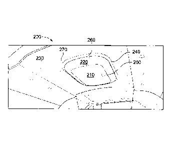
comprises: a base having generally vertical walls and an open top fastened to
a support
structure proximate a ceiling; a replaceable stowage bin at least partially
inserted through
the base into the ceiling; a closeable door suspended below the stowage bin;
and a
replaceable equipment palette fastened to an interior side of the closeable
door.
1
CA 02908605 2015-09-30
WO 2014/165821
PCT/US2014/033076
[0005] According to another embodiment, a method of installing an overhead
equipment stowage pod comprises: installing a base having generally vertical
walls and an
open top in a ceiling by fastening the base to a support structure above a
level of a ceiling
panel; forming a replaceable stowage bin to compensate for obstacles between
the
generally vertical walls above the level of the ceiling panel; fastening the
replaceable
stowage bin to the base when at least partially inserted through the base into
the ceiling;
attaching a closeable door to the base; and fastening a replaceable equipment
palette to an
interior side of the closeable door to be accessible when the closeable door
is opened.
[0006] According to another embodiment, an overhead equipment stowage pod
apparatus comprises a base having a structural material surrounding a central
opening.
The central opening is open on top and bottom, and the base is fastened to a
support
structure proximate a ceiling. A replaceable stowage bin is at least partially
inserted
through the base into the ceiling, and a closeable door is suspended below the
stowage bin.
[0007] The apparatus may further comprise a replaceable equipment palette
fastened to an interior side of the closeable door.
[0008] The replaceable equipment palette may include at least one of
emergency
equipment and entertainment equipment.
[0009] The apparatus may further include a bezel that surrounds the base
proximate the ceiling, and the bezel may include a lighting element that
shines light.
[00010] The apparatus may further include a bezel that surrounds the base
below a
level of the ceiling, leaving a gap between the ceiling and the bezel. The
bezel may
include a lighting element that shines light onto the ceiling surrounding the
bezel from
within the gap between the ceiling and the bezel.
[00011] The apparatus may further include a ceiling panel that includes a
cutout
into which the base is inserted, and a recessed pod well surrounding the base.
[00012] The apparatus may further include a bezel that surrounds the base
below a
level of the recessed pod well, leaving a gap between the recessed pod well
and the bezel.
The bezel may include a lighting element that shines light onto the recessed
pod well
surrounding the bezel from within the gap between the recessed pod well and
the bezel,
and the recessed pod well may be contoured upward above the bezel and
configured as a
light wash to disperse the light shined by the lighting element.
2
CA 02908605 2015-09-30
WO 2014/165821
PCT/US2014/033076
[00013] The apparatus may further include a lift assist unit attached to
the base and
the closeable door that assists in raising and lowering the closeable door.
[00014] The replaceable stowage bin may include a molded feature formed to
accommodate an obstacle in the ceiling.
[00015] The apparatus may further include a plurality of tie rods that
attach the base
to the support structure.
[00016] According to another embodiment, an overhead equipment stowage pod
apparatus includes a base having generally vertical walls and an open top
fastened to a
support structure proximate a ceiling, a ceiling panel that includes a cutout
into which the
base is inserted, and a recessed pod well surrounding the base. The apparatus
also
includes a bezel that surrounds the base below a level of the recessed pod
well, leaving a
gap between the recessed pod well and the base. The bezel includes a lighting
element
that shines light onto the recessed pod well surrounding the bezel from within
the gap
between the recessed pod well and the base. The recessed pod well is contoured
upward
above the bezel and configured as a light wash to disperse the light shined by
the lighting
element. A replaceable stowage bin is at least partially inserted through a
central opening
in the base into the ceiling, a closeable door is suspended below the stowage
bin, and a
replaceable equipment palette fastened to an interior side of the closeable
door.
[00017] The apparatus may further include a lift assist unit attached to
the base and
the closeable door that assists in raising and lowering the closeable door.
[00018] The replaceable stowage bin may include a molded feature formed to
accommodate an obstacle in the ceiling.
[00019] The apparatus may further include a plurality of tie rods that
attach the base
to the support structure.
[00020] According to another embodiment, a method of installing an overhead
equipment stowage pod includes installing a base having structural material
surrounding a
central opening in a ceiling by fastening the base to a support structure
above a level of a
ceiling panel. The central opening being open on top and bottom. The method
also
includes forming a replaceable stowage bin to compensate for obstacles above
the central
opening of the base and above the level of the ceiling panel, fastening the
replaceable
3
CA 02908605 2015-09-30
WO 2014/165821
PCT/US2014/033076
stowage bin to the base when at least partially inserted through the central
opening of the
base into the ceiling, and attaching a closeable door to the base.
[00021] The method may further include fastening a replaceable equipment
palette
to an interior side of the closeable door to be accessible when the closeable
door is opened.
[00022] The method may further include surrounding the base with a bezel
proximate the ceiling, and shining light from the bezel.
[00023] The light may shine onto the ceiling surrounding the bezel from
within a
gap between the ceiling and the bezel.
[00024] The light may shine onto a recessed pod well surrounding the bezel
from
within a gap between the recessed pod well and the bezel, and the recessed pod
well may
be contoured upward above the bezel and disperse the light.
[00025] The method may further include opening the closeable door to reveal
the
stowage bin in the central opening of the base, removing the replaceable
stowage bin from
within the central opening of the base, accessing equipment behind the ceiling
panel
through the central opening of the base, replacing the replaceable stowage bin
within the
central opening of the base, and closing the closeable door.
[00026] While the exemplary embodiments described herein are presented in
the
context of an aircraft cabin, these embodiments arc exemplary only and are not
to be
considered limiting. The embodiments of the apparatus are not limited to use
in an aircraft
cabin. The embodiments may be used in various other vehicles including, but
not limited
to, spacecraft, ships, buses, trains, recreational vehicles, trucks,
automobiles, and the like.
Embodiments of the apparatus may also be used in homes, offices, hotels,
factories,
warehouses, garages, and other locations where it may be desirable to have
equipment
stowage in an overhead pod.
BRIEF DESCRIPTION OF THE DRAWINGS
[00027] Exemplary embodiments will be explained in more detail with
reference to
the attached drawings in which the embodiments are illustrated as briefly
described below.
[00028] FIG. 1 is a perspective view that illustrates an aircraft cabin
including an
overhead equipment stowage pod, according to an embodiment.
4
CA 02908605 2015-09-30
WO 2014/165821
PCT/US2014/033076
[00029] FIG. 2 is a close-up perspective view that illustrates an overhead
equipment
stowage pod in a closed position, according to an embodiment.
[00030] FIG. 3 is a close-up perspective view that illustrates an overhead
equipment
stowage pod in an open position, according to an embodiment.
[00031] FIG. 4 is a flow chart that illustrates a method of installing an
overhead
equipment stowage pod, according to an embodiment.
[00032] FIG. 5 is a flow chart that illustrates a method of accessing
equipment
behind a ceiling panel through an overhead equipment stowage pod, according to
an
embodiment.
DETAILED DESCRIPTION
[00033] FIG. 1 is a perspective view that illustrates an aircraft cabin
including an
overhead equipment stowage pod 150, according to an embodiment. The overhead
equipment stowage pod 150 may include a container, bin, or bucket recessed
into a ceiling
140 of the aircraft cabin, for example above an aisle 110 in a central region
of the aircraft
cabin away from sidewalls 130 and adjacent rows of seats 120. The overhead
equipment
stowage pod 150 may have a contoured exterior that complements the interior of
the
aircraft cabin so that the overhead equipment stowage pod 150 may blend in
with the
decor and ambiance of the aircraft cabin.
[00034] The overhead equipment stowage pod 150 may have a portion
protruding
downward from the ceiling 140 sufficiently far that a person may be able to
reach a handle
of the overhead equipment stowage pod 150 to access its contents without
standing on a
stepstool or ladder. For example, in an embodiment, a person who stands five
feet three
inches tall may be able to reach upward to grasp a handle of the overhead
equipment
stowage pod 150, pull downward, and open the overhead equipment stowage pod
150 to
access equipment stored inside.
[00035] While the overhead equipment stowage pod 150 is shown in FIG. 1 as
being toward a back of an aircraft cabin, this should not be construed as
limiting. The
overhead equipment stowage pod 150 may be installed in the ceiling in various
other
locations of the aircraft, for example toward a front of the aircraft cabin,
along one or
CA 02908605 2015-09-30
WO 2014/165821
PCT/US2014/033076
more aisles of the aircraft cabin, in a ceiling of a galley of the aircraft,
and generally in any
location in which stowage of equipment in the ceiling of the aircraft would be
beneficial.
[00036] FIG. 2 is a close-up perspective view that illustrates an overhead
equipment
stowage pod 200 in a closed position, according to an embodiment. The overhead
equipment stowage pod 200 may be an embodiment of the overhead equipment
stowage
pod 150 of FIG. 1. The overhead equipment stowage pod 200 includes a door 210
that
may be opened by operating a door handle 250. The overhead equipment stowage
pod
200 also includes a bezel 220 surrounding the door 210. The bezel 220 may be
installed
using one or more fasteners, and may be interchangeable or individually
replaceable. In
various embodiments, the bezel 220 may be a decorative bezel that complements
the decor
of the aircraft cabin. The overhead equipment stowage pod 200 may be installed
in the
ceiling of the aircraft cabin in conjunction with a ceiling panel 230 that
includes a cutout
into which the overhead equipment stowage pod 200 is inserted, and a recessed
pod well
240 surrounding the overhead equipment stowage pod 200. The ceiling panel 230
may be
modular and replace a conventional ceiling panel that does not include an
overhead
equipment stowage pod in an existing aircraft. The ceiling panel 230 may be
customized
in shape, color, materials, and size to replace an appropriate section of
existing ceiling
panel in an existing aircraft, thereby facilitating installation of the
overhead equipment
stowage pod 200 in an existing aircraft as a retrofit.
[00037] As illustrated, the bezel 220 does not reach all the way to the
ceiling panel
230, but rather leaves a gap between the bezel 220 and the recessed pod well
240. The
bezel 220 may include lighting that complements the primary lighting of the
interior of the
aircraft cabin. For example, the lighting included in the bezel 220 may shine
light 260
upward and onto the recessed pod well 240. The recessed pod well 240 may be
contoured
upward above the bezel 220 and may act as a light wash to disperse light 260
as light 270
to wash evenly on the ceiling panels and throughout the region of the aircraft
cabin in
which the overhead equipment stowage pod 200 is installed. The bezel 220 may
include
various forms of lighting, including primary cabin illumination lighting,
emergency
lighting, directional lighting for emergency egress, or any other lighting as
may be desired
in the ceiling of the aircraft cabin.
6
CA 02908605 2015-09-30
WO 2014/165821
PCT/US2014/033076
[00038] FIG. 3 is a close-up perspective view that illustrates an overhead
equipment
stowage pod 300 in an open position, according to an embodiment. The overhead
equipment stowage pod 300 may be an embodiment of the overhead equipment
stowage
pod 200 of FIG. 2. Operating the door handle 250 as illustrated in FIG. 2
causes a door
latch 340 to unlatch and open the door 210. The door 210 may then be pulled
downward
to open the overhead equipment stowage pod 300, or the door 210 may open at
least
partially under the force of gravity. The overhead equipment stowage pod 300
may
include one or more hinges 330 that attach the door 210 to a base 305 that has
a lip
generally parallel with the ceiling of the aircraft cabin. At least a portion
of the base 305
may be hidden under the bezel 220. The one or more hinges 330 may facilitate
the door
210 opening and closing while also supporting the door 210. The overhead
equipment
stowage pod 300 may include one or more lift assist units to assist in raising
and lowering
the door 210. Examples of the lift assist units are gas springs 350. While gas
springs 350
are shown in FIG. 3, this should not be construed as limiting, as various
other devices, for
example, snubbers, mechanical springs, or other devices as known in the art,
may be used
instead to assist in raising and lowering the door 210. For example, the gas
springs 350
may at least partially close the door 210 when the door 210 is released by a
person from a
fully opened position, or may slow an opening of the door 210 when the door
handle 250
is operated to release the door 210 from the closed position in the overhead
equipment
stowage pod 300.
[00039] The overhead equipment stowage pod 300 includes a base 305 having a
structural material surrounding a central opening. The structural material may
include
generally vertical walls 320 that are recessed into an opening in a ceiling of
the aircraft
cabin and an open top between the generally vertical walls 320. The generally
vertical
walls 320 may be coupled with the base 305 at about a level of the ceiling
panel 230. The
base 305 and/or generally vertical walls 320 may be fastened to a support
structure of the
aircraft, for example, a frame or tie rod. In an embodiment, the overhead
equipment
stowage pod 300 may be suspended from the airframe with six tie rods attached
to the
frame of the aircraft. This should not be construed as limiting, as in various
embodiments
the overhead equipment stowage pod 300 may be attached to a support structure
of the
aircraft in another manner to be suspended from a ceiling of the aircraft
cabin. The
7
CA 02908605 2015-09-30
WO 2014/165821
PCT/US2014/033076
overhead equipment stowage pod 300 may be fastened to the support structure
via access
through the open top between the generally vertical walls 320.
[00040] In addition, the overhead equipment stowage pod 300 includes a
replaceable lining 310 that fits into the overhead equipment stowage pod 300
between the
generally vertical walls 320. The replaceable lining 310 may also be referred
to as a
container, stowage bin, or bucket. The replaceable lining 310 may be formed as
a single
piece by a pressure forming process or vacuum forming process. The replaceable
lining
310 may be separately installed in the overhead equipment stowage pod 300
after the
overhead equipment stowage pod 300 is installed in the aircraft overhead
lining, thereby
facilitating easy access to the interior structures and components of the
aircraft overhead
lining during installation of the overhead equipment stowage pod 300 and for
service and
maintenance after the installation of the overhead equipment stowage pod 300
without
requiring removal of the overhead equipment stowage pod 300. For example,
lighting
equipment only accessible from behind the ceiling panel may be serviced by
opening the
door 210, detaching the gas springs 350, removing the replaceable lining 310,
performing
service of the lighting by accessing the lighting through the opening in the
overhead
equipment stowage pod 300 made accessible by removal of the replaceable lining
310,
then replacing the replaceable lining 310, reattaching the gas springs 350,
and finally
closing the door 210.
[00041] One or more fasteners 325 may fasten the lining 310 to the
generally
vertical walls 320. The one or more fasteners 325 may also fasten the lining
310, the base
305, and/or the generally vertical walls 320 to the support structure of the
aircraft. The
lining 310 may include one or more molded features 315 that are formed to
accommodate
various equipment, structures, and obstacles in the overhead lining of the
aircraft cabin
that may otherwise interfere with the placement of the overhead equipment
stowage pod
300. For example, the molded feature 315 may be molded to go around a duct,
electronic
control system equipment, support equipment, wiring bundles, etc. in the
overhead lining
of the aircraft. The lining 310 may be replaceable and customizable to
accommodate
different equipment, structures, and obstacles in the overhead lining of the
aircraft at
different locations where it is desired to install the overhead equipment
stowage pod 300.
This customizability facilitates the overhead equipment stowage pod 300 being
installed in
8
CA 02908605 2015-09-30
WO 2014/165821
PCT/US2014/033076
virtually any ceiling location within the aircraft, including locations having
obstacles to
the installation of a simple rectangular box.
[00042] An equipment palette 360 may be installed on an inside surface of
the door
210 for easy access by a person that opens the door 210. The equipment palette
360 may
include any of a variety of different types of equipment and sundries that may
be desirable
to have stored in the aircraft for ready access by the crew and/or passengers
of the aircraft.
For example, in the illustrated embodiment of FIG. 3, the equipment palette
360 includes a
defibrillator 361, a personal breathing equipment (PBE) or smoke hood 362, a
water fire
extinguisher 363, a halon fire extinguisher 364, and gloves 365. In various
other
embodiments, the equipment palette 360 may include flight safety demonstration
equipment; entertainment equipment such as portable DVD players; linens;
blankets;
pillows; first aid kits; various types of emergency equipment; in flight
service items such
as cups, utensils, plates, and napkins; personal items; luggage for the crew
of the aircraft;
or any other items that would otherwise occupy passenger luggage bins,
closets,
cupboards, or other space of a conventional aircraft without the equipment
stowage pod
300.
[00043] The equipment palette 360 may be fastened to the inside surface of
the door
210 using one or more fasteners 370. The equipment palette 360 may be
replaceable
simply by unfastening the equipment palette 360 and replacing it with a
replacement
equipment palette 360. Therefore, equipment stored in the equipment palette
360 may be
easily replaced as a group simply by removing the old equipment palette 360
and inserting
a new equipment palette 360. By so doing, not only may the equipment in the
equipment
palette 360 be replaced, but the selection of equipment in the equipment
palette 360 may
be changed. For example, if the equipment palette 360 contains emergency
equipment
that is certified for use up until an expiration date, and at about the time
of the expiration
date it is desired to replace the emergency equipment with newer emergency
equipment
having an expiration date further into the future, the entire equipment
palette 360 may be
easily replaced during a routine servicing of the aircraft without needing to
individually
track and replace each and every item in the equipment palette 360. This can
result in
savings in service time of the aircraft, as well as logistics and storage of
the equipment
installed in the equipment palette 360.
9
CA 02908605 2015-09-30
WO 2014/165821
PCT/ES2014/033076
[00044] The one or more fasteners (e.g., for the bezel 220, fasteners 325,
and/or
fasteners 370) may include nails, screws, rivets, bolts, magnets, pins, pegs,
clips, snaps,
hook and loop fasteners, adhesives, or other fasteners as known in the art. In
some
embodiments, the lining 310 may snap into place, the bezel 220 may snap into
place,
and/or the equipment palette 360 may snap into place and be held in place by
friction
and/or tabs that are engaged when snapping into place.
[00045] Components of the overhead equipment stowage pod 300 may be
constructed of or include composite materials, plastic materials, metal
materials, and/or
glass materials. For example, the base 305 and walls 320 may be constructed of
a
composite material. The replaceable lining 310 and the bezel 220 may be
constructed of a
pressure or thermal formed plastic material, and the door 210 may be
constructed of a
composite or aluminum honeycomb panel.
[00046] The interchangeable and customizable bezel 220 and lining 310
facilitate
modularity and flexibility in installation in a variety of aircraft and a
variety of locations of
an otherwise same overhead equipment stowage pod. This in turn facilitates a
same
equipment palette 360 being compatible for installation in any of the aircraft
types and
locations in which the overhead equipment stowage pod is installed. This
facilitates
savings in logistics and storage of equipment palettes 360 for aircraft fleets
that encompass
a variety of different types of aircraft.
[00047] Embodiments of the overhead equipment stowage pod described herein
make otherwise unusable dead space above the ceiling of an aircraft panel
productive as
stowage space to free up other space onboard the aircraft such as overhead
luggage bins,
closets, drawers, galley inserts, and floor space for more productive use. In
a commercial
aircraft, this may result in additional revenue-generating opportunities.
[00048] FIG. 4 is a flow chart that illustrates a method of installing an
overhead
equipment stowage pod, according to an embodiment. The overhead equipment
stowage
pod discussed with reference to FIG. 4 may be an embodiment of the overhead
equipment
stowage pod 150, 200, or 300 of FIG. 1,2, or 3. In a step 410, abase having
structural
material surrounding a central opening is installed in a ceiling by fastening
the base to a
support structure above a level of a ceiling panel. The central opening is
open on both top
and bottom. In a step 420, a replaceable stowage bin is formed to compensate
for
CA 2908605 2017-03-22
obstacles above the central opening of the base and above the level of the
ceiling panel. In
a step 430, the replaceable stowage bin is fastened to the base when at least
partially
inserted through the central opening of the base into the ceiling. The
replaceable stowage
bin may be fully inserted through the central opening of the base, in an
embodiment. In a
step 440, a closeable door is attached to the base. The closeable door may be
suspended
below the base and the replaceable stowage bin. The closeable door may be
attached to
the base with one or more hinges, one or more lift assist units, or both. In a
step 450, a
replaceable equipment palette is fastened to an interior side of the closeable
door to be
accessible when the closeable door is opened. In a step 460, the base is
surrounded with a
bezel proximate the ceiling, and light is shined from the bezel. In an
embodiment, the
light shines onto the ceiling surrounding the bezel from within a gap between
the ceiling
and the bezel. In another embodiment, the light shines onto a recessed pod
well
surrounding the bezel from within a gap between the recessed pod well and the
bezel. In
this embodiment, the recessed pod well is contoured upward above the bezel and
disperses
the light.
[00049] FIG. 5 is a flow chart that illustrates a method of accessing
equipment
behind a ceiling panel through an overhead equipment stowage pod, according to
an
embodiment. The overhead equipment stowage pod discussed with reference to
FIG. 5
may be an embodiment of the overhead equipment stowage pod 150. 200, or 300 of
FIG.
1, 2, or 3. In a step 510, a closeable door of an overhead equipment stowage
pod is
opened to reveal a stowage bin in a central opening of a base of the stowage
pod. In a step
520, the replaceable stowage bin is removed from within the central opening of
the base.
In a step 530, equipment behind the ceiling panel is accessed through the
central opening
of the base. In a step 540, the replaceable stowage bin is replaced within the
central
opening of the base. In a step 550, the closeable door is closed, covering the
central
opening of the base.
[00050] For the purposes of promoting an understanding of the principles of
the
invention, reference has been made to the embodiments illustrated in the
drawings, and
specific language has been used to describe these embodiments. However, no
limitation
of the scope of the invention is intended by this specific language, and the
invention
should be construed to encompass all embodiments that would normally occur to
one of
11
CA 2908605 2017-03-22
ordinary skill in the art. The terminology used herein is for the purpose of
describing the
particular embodiments and is not intended to be limiting of exemplary
embodiments of
the invention. In the description of the embodiments, certain detailed
explanations of
related art are omitted when it is deemed that they may unnecessarily obscure
the essence
of the invention.
[00051] The use of any and all examples, or exemplary language (e.g., "such
as")
provided herein, is intended merely to better illuminate the invention and
does not pose a
limitation on the scope of the invention unless otherwise claimed. Numerous
modifications and adaptations will be readily apparent to those of ordinary
skill in this art
without departing from the spirit and scope of the invention as defined by the
following
claims. Therefore, the scope of the invention is defined not by the detailed
description of
the invention but by the following claims, and all differences within the
scope will be
construed as being included in the invention.
[00052] No item or component is essential to the practice of the invention
unless the
element is specifically described as "essential" or "critical". It will also
be recognized that
the terms "comprises," "comprising," "includes." "including," "has," and
"having," as
used herein, are specifically intended to be read as open-ended terms of art.
The use of the
terms "a" and "an" and "the" and similar referents in the context of
describing the
invention (especially in the context of the following claims) are to be
construed to cover
both the singular and the plural, unless the context clearly indicates
otherwise. In addition,
it should be understood that although the terms "first," "second," etc. may be
used herein
to describe various elements, these elements should not be limited by these
terms, which
are only used to distinguish one element from another. Furthermore, recitation
of ranges
of values herein are merely intended to serve as a shorthand method of
referring
individually to each separate value falling within the range, unless otherwise
indicated
herein, and each separate value is incorporated into the specification as if
it were
individually recited herein.
12