Note : Les descriptions sont présentées dans la langue officielle dans laquelle elles ont été soumises.
CA 02908694 2015-11-04
DESCRIPTION
POWER GENERATION METHOD
TECHNICAL FIELD
[0001] The present invention relates to a power generation method, especially
by converting
all or a part of kinetic energy of an object, which is present at a high place
in nature, into
potential energy and then using the potential energy to generate power in a
desired time.
BACKGROUND ART
[0002] In recent years, because of the nuclear leakage accident of the nuclear
power plant
caused by Great East Japan Earthquake, movements to return to the power
generation using
natural energy have been increased.
[0003] Regarding a power generation method using natural energy, following
examples were
proposed in the past. For example, as shown in Japanese Patent Application
Publication
2011-91986, a method by breaking down a steep mountain and generating power
using
potential energy of dirt when transferring the dirt to a low place was
proposed. For example, as
shown in Japanese Patent Application Publication 2010-275992, a method by
rotating a bucket
conveyor using gravity of water and buoyancy of air bubble to rotate a gear
and transferring
rotational force of the gear to a power generator to generate power was
proposed. For example,
as shown in Japanese Patent Application Publication H11-266553, a method by
lifting high
weight object and hold it by a hydraulic jack using natural energy such as
wind power and
wave power to store potential energy and converting the potential energy into
kinetic energy as
needed to generate power was proposed.
PRIOR ART DOCUMENTS
[Patent Documents]
[0004] Patent Document 1: Japanese Patent Application Publication H11-266553
Patent Document 2: Japanese Patent Application Publication 2010-275992
Patent Document 3: Japanese Patent Application Publication 2011-91986
1
CA 02908694 2015-11-04
DISCLOSURE OF THE INVENTION
[Problems to be Solved by the Invention]
[0005] However, in the above described "method of breaking down a steep
mountain" and
"method of using gravity of water and buoyancy of air bubble", there is no
concept of storing
energy. On the other hand, in the above described "method of using a hydraulic
jack", although
energy can be stored, an amount of energy to be stored is limited by
performance of the
hydraulic jack.
[0006] The present invention provides a power generation method capable of
storing natural
energy without specific limitations and capable of taking out the natural
energy as needed to
generate power.
[Means for Solving the Problem]
[0007] A power generation method concerning one aspect of the present
invention has a
potential energy storage step and a power generation step. In the potential
energy storage step,
a bucket conveyor is driven by using a rotational force of a rotating body
that is rotationally
driven by a kinetic energy produced when a first object, which is present at a
high place in
nature, falls and a plurality of second objects is continuously transferred
from a low place to the
high place. In the power generation step, the second objects are made to fall
as needed and a
power generator is operated by using a kinetic energy of the second objects.
Here, the bucket
conveyor is connected with the power generator via an interrupter. The
interrupter
mechanically connects and disconnects the bucket conveyor with/from the power
generator. In
the potential energy storage step, the bucket conveyor is mechanically
disconnected from the
power generator by the interrupter, a motive power of the bucket conveyor
produced by a fall
of the first object is not transferred to the power generator, and the
plurality of second objects is
continuously transferred from the low place to the high place. On the other
hand, in the power
generation step, the bucket conveyor is mechanically connected with the power
generator by
the interrupter, and the motive power of the bucket conveyor produced by a
fall of the second
objects is transferred to the power generator to operate the power generator.
Note that it is
preferred that the second objects are transferred to the bucket conveyor by an
electric forklift
driven by electricity produced by the power generator.
[0008] In this power generation method, as long as the first object is present
at the high place,
the plurality of second objects can be transferred from the low place to the
high place without
specific limitations to store the natural energy of object falling, and the
power generator can be
operated by falling the second objects at an appropriate timing. Therefore, by
using this power
2
CA 02908694 2015-11-04
generation method, the natural energy can be stored without specific
limitations and power can
be generated by taking out the natural energy as needed.
[0009] A power generation method concerning another aspect of the present
invention has a
potential energy storage step and a power generation step. In the potential
energy storage step,
a bucket conveyor is driven by using a rotational force of a rotating body
that is rotationally
driven by a kinetic energy produced when a first object, which is present at a
high place in
nature, falls and a plurality of second objects can be continuously
transferred from a low place
to the high place. In the power generation step, the second objects are made
to fall as needed
and a power generator can be operated by using a kinetic energy of the second
objects. Here,
the bucket conveyor is comprised of a first bucket conveyor connected with the
power
generator and a second bucket conveyor connected with the first bucket
conveyor via an
interrupter. The interrupter mechanically connects and disconnects the first
bucket conveyor
with/from the second bucket conveyor. In the potential energy storage step,
the first bucket
conveyor is mechanically connected with second bucket conveyor by the
interrupter, a motive
power of the second bucket conveyor produced by a fall of the first object is
transferred to the
first bucket conveyor, and the plurality of second objects is continuously
transferred from the
low place to the high place by the first bucket conveyor. On the other hand,
in the power
generation step, the first bucket conveyor is mechanically disconnected from
the second bucket
conveyor by the interrupter, the motive power of the first bucket conveyer
produced by a fall of
the second objects is not transferred to the second bucket conveyor, and the
power generator is
operated by the first bucket conveyer. Note that it is preferred that the
second objects are
transferred to the first bucket conveyor by an electric forklift driven by
electricity produced by
the power generator. It is preferred that the first object is a dirt, a rock
or a snow of a
mountaintop and the second bucket conveyer is obliquely arranged along a
mountain surface. It
is preferred that the first object is transferred to the second bucket
conveyer by an electric
forklift driven by electricity produced by the power generator.
In this power generation method, as long as the first object is present at the
high
place, the plurality of second objects can be transferred from the low place
to the high place
without specific limitations to store the natural energy of object falling,
and the power
generator can be operated by falling the second objects at an appropriate
timing. Therefore, by
using this power generation method, the natural energy can be stored without
specific
limitations and power can be generated by taking out the natural energy as
needed.
3
CA 02908694 2015-11-04
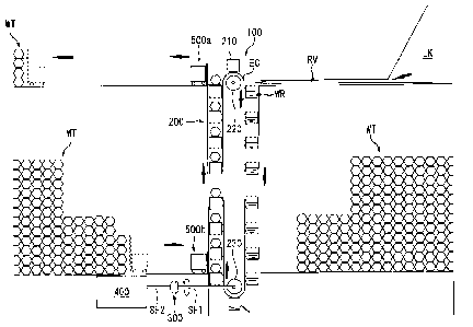
BRIEF DESCRIPTION OF THE DRAWINGS
[0010] Fig. 1 is a schematic diagram showing a state that kinetic energy
produced by a fall of
water is converted to potential energy concerning a power generation system of
an embodiment
of the present invention.
Fig. 2 is a schematic diagram showing a state that power is generated by using
the
stored potential energy concerning a power generation system of an embodiment
of the present
invention.
Fig. 3 is a schematic diagram showing a power generation system concerning a
variation example (E).
Fig. 4 is a perspective view of a bucket shown in Fig. 1 to Fig. 3.
MODE FOR CARRYING OUT THE INVENTION
[0011] <Components of power generation system>
A power generation system 100 of an embodiment of the present invention is
mainly
formed by a bucket conveyor 200, an interrupter 300, a power generator 400,
and electric
forklifts 500a, 500b as shown in Fig. 1 and Fig. 2. Hereafter, these
components will be
explained in detail.
[0012] (1) Bucket conveyor
The bucket conveyor 200 is arranged on a downstream side in a flow direction
of
water WR, which flows from a lake LK into a river RV. The bucket conveyor 200
is mainly
formed by a bucket 210, an endless chain EC, an upper gear 220 and a lower
gear 230.
[0013] As shown in Fig. 4, the bucket 210 is a container having an
approximately cubic
shape and having a grid cover 215. Namely, an upper side of the bucket 210 is
open. One side
wall of the bucket 210 is connected with the endless chain EC. Specifically,
as shown in Fig. 1,
an opening of the bucket 210 faces upward at one side and faces downward at
the other side.
Note that, in the present embodiment, a plurality of buckets 210 is connected
with the endless
chain EC as shown in Fig. 1. In addition, a grid interval of the grid cover
215 is smaller than a
size of the latter mentioned weight WT so that the weight WT does not pass
through the grid
cover 215.
[0014] The endless chain EC is formed between the upper gear 220 and the lower
gear 230.
[0015] The upper gear 220 and the lower gear 230 are engaged with the endless
chain EC
respectively at an upper side and a lower side. Note that both the upper gear
220 and the lower
gear 230 are not connected with a driving source. In addition, the lower gear
230 is connected
with a bucket conveyor-side shaft SF1 via a not illustrated worm gear.
Therefore, when the
4
CA 02908694 2015-11-04
lower gear 230 is rotated, the bucket conveyor-side shaft SF1 is rotated
around its axis.
Note that the bucket conveyor-side shaft SF1 can be connected with the upper
gear
220 without limited to the lower gear 230. In such a case, the later mentioned
interrupter 300
and power generator 400 should be arranged on a side of a high place.
As explained above, the bucket conveyor includes: the endless chain EC that is
formed between the upper gear 220 arranged at a high place and the lower gear
230 arranged at
a low place and engaged with the upper gear 220 and the lower gear 230; the
bucket 210 that is
a container having an opening at an upper side; and the bucket conveyor-side
shaft SF1 that is
connected to either the upper gear 220 or the lower gear 230 via a gear to be
rotated around an
axis of the bucket conveyor-side shaft SF1 when the lower gear 230 is rotated.
In addition,
the grid cover 215 is attached to the opening, a grid interval of the grid
cover 215 is smaller
than a size of the weight WT, one side wall of the bucket 210 is connected
with the endless
chain EC, and the opening faces upward at one side of the endless chain EC and
the opening
faces downward at the other side between the upper gear 220 and the lower gear
230.
[0016] (2) Interrupter
As shown in Fig. 1 and Fig. 2, the interrupter 300 mechanically connects and
disconnects the bucket conveyor-side shaft SF1 with/from a power generator-
side shaft SF2.
[0017] (3) Power generator
The power generator 400 is a general power generator. In the present
embodiment, the
generator is not particularly limited.
[0018] (4) Electric forklift
The electric forklifts 500a, 500b are respectively arranged at an upstream
side and a
downstream side of the bucket conveyor 200. Note that, in the embodiment, the
electric
forklifts 500a, 500b are driven by a large-size secondary battery that is
charged with electric
energy produced by the power generator 400.
[0019] <Operating method of power generation system>
The power generation system 100 of the present embodiment can take two states,
i.e.,
a potential energy storage state and a power generation state. Hereafter,
operations of the power
generation system 100 in each state will be explained in detail.
[0020] (1) Potential energy storage state
In the potential energy storage state, as shown in Fig. 1, the interrupter 300
mechanically disconnects the connection between the bucket conveyor-side shaft
SF1 and the
power generator-side shaft SF2. In this state, if the water WR flows from the
river RV into the
bucket 210, the bucket 210 is pushed down by a fall of the water WR, then the
endless chain
EC starts to rotate and the upper gear 220 and the lower gear 230 are rotated
accordingly. When
the next bucket 210 is moved to a fall position of the water WR, the water WR
flows into the
5
CA 02908694 2015-11-04
next bucket 210 to rotate the endless chain EC in the same way. The above
described state is
repeated and the endless chain EC, the upper gear 220 and the lower gear 230
are continuously
rotated. Note that the water WR flowing into the bucket 210 is discharged
downward at a
position immediately below the lower gear 230 because the opening of the
bucket 210 faces
sideways. In addition, as shown in Fig. 1, when the bucket 210 is moved from
the lower side to
the upper side, the opening of the bucket 210 faces downward, i.e., a bottom
wall of the bucket
210 faces upward.
[0021] While the endless chain EC is rotated as described above, the weight WT
is placed on
an opposite side of the bottom wall of the bucket 210 by the electric forklift
500b of the
downstream side in a direction of falling water, the weight WT is removed from
the bucket 210
by the electric forklift 500a of the upstream side in the direction of falling
water, and the weight
WT is stored at the high place. Thus, energy of water falling is stored as the
potential energy.
In the potential energy storage step, the bucket conveyor is mechanically
disconnected
from the power generator by mechanically disconnecting the bucket conveyor-
side shaft SF1
from the power generator-side shaft SF2 by using the interrupter 300. Thus,
the motive power
of the bucket conveyor produced when the bucket conveyor-side shaft SF1 is
rotated by the fall
of the water WR, which is the first object, is not transferred to the power
generator. In addition,
the weight WT, which is the plurality of second objects, is continuously
transferred from the
low place, which is the downstream side in the direction of falling water, to
the high place,
which is the high place.
In the potential energy storage step, the bucket 210 is opened upward at one
side of
the endless chain EC of the bucket conveyor. In this state, if the water WT,
which is the first
object, is entered in the bucket 210 from above at the high place, which is
the upstream side in
the direction of falling water, the water WT is stored in the bucket 210, a
weight of the water
WT functions to push down the bucket 210, the endless chain EC is pushed down,
and whole
the endless chain EC is rotated in one direction.
When the bucket 210 storing the water WT reaches the lowest point of the
downstream side in the direction of falling water, the bucket 210 is rotated
together with the
endless chain EC along the lower gear 230. Therefore, the water WT in the
bucket 210 is
automatically discharged. The bucket 210 starts to move from lower to upper at
the other side
of the endless chain EC in accordance with the movement of the endless chain
EC.
At that time, the opening of the bucket 210 faces downward. Therefore, the
weight
WT can be placed on an opposite side of a bottom of the bucket 210. By placing
the weight
WT on the opposite side, the weight WT is transferred from the downstream side
in the
direction of falling water to the upstream side in the direction of falling
water.
[0022] (2) Power generation state
6
CA 02908694 2015-11-04
In the power generation state, as shown in Fig. 2, the interrupter 300
mechanically
connects the bucket conveyor-side shaft SF1 with the power generator-side
shaft SF2. In this
state, if the weight WT is placed on the grid cover 215 of the bucket 210 by
the electric forklift
500a of the upstream side in the direction of falling water, the bucket 210 is
pushed down by a
fall of the weight WT, the endless chain EC starts to rotate, and the upper
gear 220 and the
lower gear 230 are rotated accordingly. When the next bucket 210 reaches a
loading position of
the weight WT, another weight WT is placed on the grid cover 215 of the next
bucket 210 by
the electric forklift 500a again and the endless chain EC is rotated. The
above described state is
repeated to rotate the endless chain EC, the upper gear 220 and the lower gear
230 continuously.
Thus, the rotational force of the lower gear 230 is transferred to the power
generator 400 via the
bucket conveyor-side shaft SF1, the interrupter 300 and the power generator-
side shaft SF2,
and power is generated. Note that the weight WT placed on the grid cover 215
of the bucket
210 is removed from the bucket 210 at a position near the lower gear by the
electric forklift
500b of the downstream side in the direction of falling water, and the weight
WT is stored at
the low place.
In the power generation step, the bucket conveyor is mechanically connected
with the
power generator by mechanically connecting the bucket conveyor-side shaft SF1
with the
power generator-side shaft SF2 by using the interrupter 300. In this state, if
the weight WT,
which is the second objects, is placed on the grid cover 215 of the bucket
210, the bucket 210 is
pushed down by a fall of the weight WT, the endless chain EC starts to rotate,
and the upper
gear 220 and the lower gear 230 are rotated accordingly. The motive power of
the bucket
conveyor produced by a fall of the weight WT is converted to the rotational
force of the lower
gear 230, and the rotational force is transferred to the power generator 400
via the bucket
conveyor-side shaft SF1, the interrupter 300 and the power generator-side
shaft SF2 to operate
the power generator 400.
In the power generation step, although the bucket 210 is opened upward at one
side of
the endless chain EC of the bucket conveyor, the weight WT can be placed on
the grid cover
215 because the grid cover 215 is attached. In this state, a weight of the
weight WT, which is
the second objects, functions to push down the bucket 210 from above at the
high place, which
is the upstream side in the direction of falling water, the endless chain EC
is pushed down, and
whole the endless chain EC is rotated in one direction.
When the bucket 210 storing the weight WT is moved to a loading position
located
before the lowest point of the downstream side in the direction of falling
water, the weight WT
is removed from the bucket 210 and stored at the low place. A process of
placing the weight
WT on the bucket 210 at the high place and removing and storing the weight WT
at the low
place is continuously repeated.
7
CA 02908694 2015-11-04
[0023] <Feature of power generation system of embodiment>
(1)
In the power generation system 100 of the present embodiment, the energy of
water
falling of the water WR can be stored as the potential energy by using a fall
of the water WR
flowing in the river RV, and the power generator 400 can be operated by
falling the weight WT
at an appropriate timing. Therefore, by using the power generation system 100,
the potential
energy can be stored without specific limitations and the potential energy can
be taken out as
needed to generate power.
[0024] [Table 1]
total water
total inflowwater storage water storage ratio water storage ratio
3 /s) amount (km)discharge 3
amount (m (%) (%)
amount (m3/s)
78.40 82.85 6410 62.10 32.10
(setvice water (wacky)
(effective capacity)
[0025] Meanwhile, Table 1 shows the water discharge amount discharged from
Amagase
Dam from 19:00:00 to 19:00:01 on June 21, 2011 (total water discharge amount,
information
distributed on the intern& of Ministry of Land, Infrastructure, Transport and
Tourism). Before
the rainy season in Japan, unless water is discharged from Amagase Dam, there
is a risk of
burst of the dam and collapse of the house caused by flood and landslide, for
example. From
Table 1, the water discharge amount per 1 second of the above described period
is 82.8 tons.
The water discharge amount per 1 month calculated from the above data is
214,617,600 tons
(82.8 tons x 60 seconds x 60 minutes x 24 hours x 30 days). It is a waste to
leave such a large
amount of water continuously flow. Therefore, such a large amount of water can
be used
efficiently by using the power generation method of the present invention.
Although
anti-nuclear power plant is acknowledged as a problem today, the inventor of
the present
invention considers that the problem can be solved by efficiently using that.
In general, it is said
that it is technologically impossible to store electricity (alternate current)
used in a home
currently on the earth. However, the impossibility is turned to possibility by
using the power
generation method of the present invention. In other words, by using the power
generation
method of the present invention, the potential energy can be permanently and
unlimitedly
stored and power can be generated immediately at any time. Here, "permanently
and
unlimitedly" means that rain is made to fall by energy radiated from the sun
and the potential
energy of the water trapped at the high place by the rain can be converted
into the potential
energy of the weight WT and stored.
[0026] (2)
In the power generation system 100 of the embodiment, the electric forklifts
500a,
8
CA 02908694 2015-11-04
500b are driven by the large-size secondary battery that is charged with
electric energy
produced by the power generator 400. Therefore, power can be generated by
using only natural
energy.
[0027] <Variation examples>
(A)
In the power generation system 100 of the previous embodiment, the interrupter
is in a
disconnected state in the potential energy storage state. However, the
interrupter can be
continuously or intermittently connected. Thus, a part of the energy of
falling water of the
water WR can be used for the power generation and the other part of the energy
can be used for
storing the potential energy. As a result, power can be always generated any
time day or night.
[0028] (B)
In the power generation system 100 of the previous embodiment, the potential
energy
is stored and power is generated by using the water flowing in the river RV.
However, a dirt, a
rock or a snow of a mountaintop can be used instead of the water WR. In such a
case, it is
preferred that the bucket conveyor 200 is obliquely arranged along a mountain
surface. Thus, in
addition to the above described effects, land formation can be performed.
[0029] (C)
In the power generation system 100 of the previous embodiment, height
difference of
the river RV is used. However, height difference of the dam can be used
instead.
[0030] (D)
In the power generation system 100 of the previous embodiment, the electric
forklifts
500a, 500b are used for transferring the weight WT. However, a forklift
equipping a gasoline
engine can be used instead.
[0031] (E)
Although not mentioned in the previous embodiment, a power generation system
100A shown in Fig. 3 can be used as a power generation system. The power
generation system
100A is basically same as the power generation system 100 of the previous
embodiment except
for the following points: (i) a dirt and a snow is used instead of the water
WR; (ii) a bucket
conveyor 200B used only for the dirt or the snow and a bucket conveyor 200A
used for
transferring the weight and generating power are provided together; (iii) an
intermediate gear
250 engaged with the endless chain EC is provided between the lower gear 230
and the upper
gear 220 of the bucket conveyor 200A used for transferring the weight and
generating power;
(iv) an interrupter 300A is provided between the bucket conveyor 200B used
only for the dirt or
the snow and the bucket conveyor 200A used for transferring the weight and
generating power;
(v) the power generator 400 is connected to the intermediate gear 250; and
(vi) an electric
shovel car 550 is used for scraping out the dirt or the snow. Regarding the
components same as
9
CA 02908694 2015-11-04
the power generation system 100 of the previous embodiment, the same reference
numerals are
applied and explanations are omitted.
[0032] The bucket conveyor 200B used only for the dirt or the snow is mainly
formed by the
buckets 210, the endless chain EC, the upper gear 220 and the lower gear 230,
as shown in Fig.
3. The bucket conveyor 200B is basically same as the bucket conveyor 200 of
the previous
embodiment.
[0033] The interrupter 300A is in a connected state in the potential energy
storage state, and
in a disconnected state in the power generation state. Same as the power
generation system 100
of the previous embodiment, another interrupter can be arranged between the
power generator
400 and the intermediate gear 250.
[0034] Same as the electric forklifts 500a, 500b, the electric shovel car 550
is driven by a
large-size secondary battery that is charged with electric energy produced by
the power
generator 400. Note that a shovel car equipping a gasoline engine can be used
instead of the
electric shovel car 550.
[Description of the Reference Numerals]
[0035] 100, 100A: power generation system,
200, 200A, 200B: bucket conveyor,
210: bucket,
215: grid cover,
220: upper gear,
230: lower gear (rotating body),
250: intermediate gear (rotating body),
300, 300A: interrupter,
400: power generator,
500a, 500b: electric forklift,
550: electric shovel car,
EC: endless chain,
WR: water (first object),
WT: weight (second object)