Note : Les descriptions sont présentées dans la langue officielle dans laquelle elles ont été soumises.
CA 02908751 2015-10-15
LIGHTING CONTROL WITH INTEGRAL DIMMING
BACKGROUND
100011 The present disclosure generally relates to lighting control devices,
network systems,
and methodologies, including methods for providing closed-loop dimming control
of such
systems.
[0002] With respect to dimming control, some methods use arbitrary or poorly
correlated 0
through 10V dimming signals, being applied and then adjusted manually, in
order to achieve a
specific fixture wattage or derivation of a dim voltage to fixture watts
dimming command curve
to be developed for every conceivable combination of LED drivers and light
engines, in order to
predict the appropriate dimming control voltage to be applied to achieve the
desired fixture
wattage.
[0003] Some fixture controls with dimming capability require both a photo
control module (or
"node") and a separate dimming control module. In such arrangements, the photo
control
module and dimming control module may include separate unique device
identifiers, which can
be used to identify the individual module on the control network. To properly
control and
diagnose a particular fixture SKU (unique combination of driver style, driver
voltage, driver
min/max current, LED count, LED type, etc.), the input Wattage characteristics
of said fixture
SKU must be characterized over the entire 0-10V dimming control voltage range.
Aspects of this
characterization may include, the driver end-point voltage thresholds (where
the lower dead band
stops and the upper dead band starts), and the resultant fixture Wattage at
each of these two dead
band threshold voltages.
[0004] During asset installation, an activation process may capture an
identifier for the node
and the associated fixture's SKU. A node profile, specific to the fixture SKU,
is then manually
created, e.g. at a network operation center (NOC), containing the dead band
voltage thresholds.
The node profile is pushed from the NOC to the node via the control network,
and stored in the
memory of the node.
[0005] A diagnostic table within the NOC must also be manually populated with
a record
containing: SKU (X), the fixture Wattage at each dead band threshold voltage,
and node-internal
digital codes that correspond to the two dead band voltage thresholds. Within
the activation
1
CA 02908751 2015-10-15
record for each node-equipped asset, the control module device and dimming
control module
device identifiers must also be paired (manually).
[0006] When daily fixture diagnostics are performed, the NOC must predict the
expected
dimmed fixture Wattage by referring to events/commands issued to/from the
paired node
identifiers, observing the dim command active during hourly time slices during
the diagnostic
period. The prediction may be derived using y=mx+b parameters stored in the
NOC table. The
NOC then compares this prediction to the actual reported fixture Watts from
the node identifier
to determine fixture status.
[0007] However, as with other human processes, aspects of current techniques
may be
relatively labor intensive, particularly for large-scale lighting systems, and
allow for error related
to, for example, fixture status and/or design changes, manual information
entry and/or changes
to, misidentification, and/or unrecognized system components, etc. There may
also be problems
pairing the identifiers of the specific control module and dimming control
module for a given
fixture in the NOC database/table. Moreover, many of these problems may be
difficult to detect
or correct, particularly in a large-scale networked lighting control system.
SUMMARY
[0008] According to first aspects of the disclosure, systems and methods that
provide closed-
loop dimming control for intelligent lighting systems are provided. In some
examples, this can
reduce or eliminate the need for currently used fixture characterizations,
dimming profiles,
and/or NOC table record entries mentioned above, and allow for processing user
commands for
dimming control that map directly to the percentage of the fixture's rated
maximum Wattage.
[0009] The present subject matter provides, among other objects, closed-loop
dimming control
schemes that contemplate changes in hardware in tandem with firmware/NOC
software
modifications. By using, for example, 5 or 7 contact photo control (as defined
in ANSI C136.41)
fixture-integrated products, the need for manual pairing, and/or control
module identifier capture
during activation may be eliminated.
[0010] In some examples, a system for intelligent photo control may be
configured to
automatically detect key characteristics of the fixture to which it is
installed, including dimming
control capabilities and control/operation parameters. Human data entry
components of current
commissioning methods may be reduced or eliminated by incorporating automated
diagnostic
2
programs, e.g. into the photo control module firmware functionality and NOC
software
functionality.
[0001] In some examples, disclosed methods and device configurations may
include an
intelligent photo control configured to accept target dimmed fixture wattage
value commands
from a user, and provide closed-loop control at the fixture to achieve that
target wattage via
real-time adjustment of the 0-10V dimming control signal sent to the LED
driver. As such, the
need for trial-and-error adjustments of the 0-10V analog control voltage, or
derivation of dim
voltage to fixture wattage response curves in order to achieve a desired
fixture wattage level,
may be reduced or eliminated.
[0002] According to further aspects of the disclosure, a lighting fixture
control system may
include a control station configured to communicate with a plurality of
fixture control devices
located remotely from the control station, to receive a dimming command for at
least one of
the fixture control devices via a user interface, and to send a dimming
setting command to the
at least one of the fixture control devices based at least in part on the
received dimming
command. A fixture control device, that is associated with a lighting fixture,
may be located
remotely from the control station, and configured to dim the lighting fixture
via a variable
dimming control signal based at least in part on the dimming setting command
and a Wattage
measurement received from the lighting fixture, and further configured to
iteratively adjust
the dimming control signal based at least in part on the Wattage measurement.
[0003] In embodiments, the fixture control device may includes a dimming
controller
module; and a fixture power measurement module, each of which may be implanted
as
hardware and/or software components. In embodiments, the dimming controller
module may
be configured to determine a target Wattage based at least in part on the
dimming setting
command and to iteratively adjust the dimming control signal based at least in
part on a
fixture Wattage measurement obtained by the measurement module until the
fixture Wattage
measurement is within a predetermined range of the target Wattage.
[0004] In embodiments, the fixture control device may be configured to set a
target Wattage
based at least in part on the received dimming command, and to use closed-loop
feedback to
achieve the target Wattage. As used herein, closed-loop feedback should be
understood as
3
CA 2908751 2017-06-02
representing techniques that analyze the effects of a closed (feedback) loop
of a dimming
control signal (e.g. 1-10 V) provided to a lighting fixture, and that adjust
the dimming control
signal (as needed) based on the analysis. This may be performed, for example,
by a fixture
control device
3a
CA 2908751 2017-06-02
CA 02908751 2015-10-15
configured to provide a dimming control signal to a lighting fixture and to
observe a measured
wattage of the fixture in response to the dimming control signal.
[0015] In embodiments, the fixture control device may be configured to slew
the dimming
control signal until a fixture Wattage observed by the fixture control device
is within a
predetermined range of target Wattage.
[0016] In embodiments, the target Wattage may be determined based on at least
one of a table
of values associated with the lighting fixture, or a rated fixture maximum
Wattage and a
dimming setting command expressed as a percentage.
[0017] In embodiments, the fixture control device may be configured to
determine a minimum
dimmed Wattage supported by the lighting fixture via at least one iteration of
the closed-loop
feedback, and to limit attempts to dim the lighting fixture below the minimum
dimmed Wattage.
[0018] In embodiments, the fixture control device may be configured to
determine a driver
dead band via at least one iteration of the closed-loop feedback, and to limit
the dimming control
signal during subsequent dimming operations to avoid the driver dead band.
[0019] In embodiments, the dimming control signal may be a 0-10 V control
signal.
[0020] In embodiments, the fixture control device may use at least one of a
PID control loop or
a proportional control algorithm to vary the dimming control signal.
[0021] According to further aspects of the disclosure, a lighting fixture
control apparatus may
include one or more of a command receiving module configured to receive a
dimming setting
command from a remote command center; a dimming controller module; and a
fixture power
measurement module. In embodiments, the dimming controller module may be
configured to
determine a target Wattage value based at least in part on the dimming setting
command, and to
iteratively adjust a dimming control signal based at least on part on a
fixture Wattage
measurement provided by the fixture power measurement module until the fixture
Wattage
measurement is within a predetermined range of the target Wattage value.
[0022] In embodiments, the fixture control device may be configured to
determine a minimum
dimmed Wattage supported by the lighting fixture based on a plurality of the
fixture Wattage
measurements, and to limit attempts to dim the lighting fixture below the
minimum dimmed
Wattage.
4
CA 02908751 2015-10-15
[0023] In embodiments, the fixture control device may be configured to
determine a driver
dead band based on a plurality of the fixture Wattage measurements, and to
limit the dimming
control signal during subsequent dimming operations to avoid the driver dead
band.
[0024] In embodiments, the fixture control device may be configured to
override the dimming
setting command in response to a sensor event, and to set a dimming level for
the lighting fixture
to a predetermined level for a default period of time based on the sensor
event.
[0025] According to further aspects of the disclosure, a lighting fixture
control system may
include one or more of a processor; a communication device; and memory
including computer-
executable instruction that configure the processor to perform operations,
including receiving a
network identifier for a remote lighting control module associated with a
lighting fixture;
registering the lighting control module with the lighting fixture control
system; determining
whether at least one of the lighting control module or the lighting fixture
supports a dimming
function; enabling a dimming option in a user interface based on a
determination that the at least
one of the lighting control module or the lighting fixture supports a dimming
function; receiving
a dimming input control via the user interface; and/or providing a dimming
setting signal to the
lighting control module based at least in part on the received dimming input
control.
[0026] In embodiments, a message that the target dimmed fixture wattage value
or the target
dimmed fixture lumen output has been implemented by the lighting control
module may be
generated by the lighting control module and received by the lighting fixture
control system.
[0027] As discussed further below, disclosed systems and methods may provide a
dimming
controller sub-section and fixture power measurement sub-section in an
intelligent photo control
that work in conjunction to provide closed-loop dimming control. In some
examples, a user may
issue a command to the intelligent photo control to adjust the fixture to a
desired wattage and
then the closed loop control mechanism may automatically adjust the analog
dimming control
signal until that fixture wattage is achieved. Accordingly, in some examples,
the arbitrary scales
(e.g. 1-10) included in some remote dimming commands can be eliminated.
Additionally, the
requirement for calculating, and relying on, complex derivations of
potentially non-linear
response curves may be eliminated as well in certain embodiments.
[0028] Additional features, advantages, and embodiments of the invention may
be set forth or
apparent from consideration of the following detailed description, drawings,
and claims.
Moreover, it is to be understood that both the foregoing summary of the
invention and the
CA 02908751 2015-10-15
following detailed description are exemplary and intended to provide further
explanation without
limiting the scope of the invention claimed. The detailed description and the
specific examples,
however, indicate only preferred embodiments of the invention. Various changes
and
modifications within the spirit and scope of the invention will become
apparent to those skilled
in the art from this detailed description.
BRIEF DESCRIPTION OF THE DRAWINGS
[0029] The accompanying drawings, which are included to provide a further
understanding of
the invention, are incorporated in and constitute a part of this
specification, illustrate
embodiments of the invention and together with the detailed description serve
to explain the
principles of the invention. No attempt is made to show structural details of
the invention in
more detail than may be necessary for a fundamental understanding of the
invention and various
ways in which it may be practiced. In the drawings:
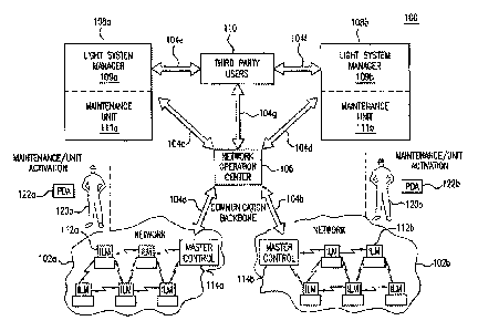
[0030] FIG. 1 illustrates a light management system in which automatic dimming
control
systems and methods according to the disclosure may be implemented.
[0031] FIG. 2 is a schematic diagram depicting aspects of a closed-loop
dimming control,
according to an exemplary embodiment of the present disclosure.
[0032] FIG. 3 is a flow chart depicting aspects of a closed-loop dimming
control, according to
an exemplary embodiment of the present disclosure.
DETAILED DESCRIPTION
[0033] Various example embodiments of the present disclosure will be described
below with
reference to the drawings constituting a part of the description.
[0034] FIG. 1 from US Patent No. 8,594,976 is shown below, and generally
illustrates an
environment in which a light management system 100, having networked
intelligent luminaire
managers 112, may be modified and/or incorporate aspects of the present
disclosure.
[0035] As shown in FIG. 1, a light management system 100 includes networks
102a and 102b,
a network operation center 106, light system owner/operators 108a and 108b,
and third-party
users 110. These subsystems of system 100 are linked together using
appropriate communication
means such as, for example, radio frequency communications, optical
communications and/or
power line carrier to form communications backbone 104.
6
CA 02908751 2015-10-15
[0036] Each of the networks 102a and 102b includes several intelligent
luminaire managers
(ILMs) 112 and a master control 114. The intelligent luminaire managers 112
communicate with
each other and with master controller 114 using, for example, short-range
radio frequency (RF)
communication links. In some examples, these RF communication links may
operate in the 900
MHz unlicensed band and have a range of about 1000 feet, but it will be
appreciated that other
frequencies and ranges may be utilized as well. Each of the intelligent
luminaire managers 112
may control operation and/or diagnostics of a light fixture, street light,
etc., which may also be
referred to as a luminaire. It should be appreciated that, as discussed
further below, incorporation
of techniques described herein may significantly reduce both the amount of
work manually
performed during activation of ILMs by technicians, such as 120a and 120b, and
reduce or
eliminate the use of PDA hosted field units, such as 122a and 122b.
[0037] According to aspects of the disclosure, intelligent luminaire managers
may include one
or more processors, memory, and an interface subsystem. The memory may store a
variety of
programs that are executed and/or implemented using the processor. These
programs may
include, for example, a luminaire control program, luminaire and intelligent
luminaire manager
configuration program, status reporting program, and other optional programs,
such as an
automated dimming control program discussed further herein.
[0038] Examples may include configuring intelligent lighting fixture control
modules to
include an activation and learning mode, which may be leveraged by a closed-
loop dimming
control process discussed further below. When a module is installed to a
fixture, an automated
activation process may be initiated including capturing a single network
identifier (such as a
MAC ID) for the control module. The network identifier may be communicated to
a NOC (e.g.
in an activation request message) as part of registering the node with the
NOC. In some
examples, the NOC may determine, e.g. by previously populated data tables,
whether the fixture
and/or control module support dimming, and may enable or disable a dimming
option in a UI at
the NOC based on the results of the determination.
[0039] In some examples, control of the node may default to, or be instructed
to initiate or
proceed with, a learning mode for some period, e.g. after initial power-up and
during a first lamp
on period. In the learning mode, the control module may determine the maximum
fixture
wattage available, e.g. with a 10V analog control signal applied. After
performing such steps, a
dimming output control may be reset to normal, adhering to previous commands,
soft limits or
schedule(s).
7
CA 02908751 2015-10-15
[0040] Examples may include a dimming control UI (e.g. implemented on a NOC
control
station), and a closed-loop dimming control onboard the control module (node).
[0041] In current systems, a control portal UI may be configured to provide a
0-100%
adjustment range for a dimmable asset. In some systems, this may correspond to
the % of the
range of adjustment allowed by the driver, not the % of rated fixture output
(effectively
maximum light output). This can lead to user/customer confusion regarding
actual Wattage
settings, requiring generation and reference to conversion tables to map
between UI % and
fixture Wattage %. However, according to aspects of the present disclosure, a
UI % can be
configured to map directly to the % of rated max fixture Wattage, providing
the user/customer
with more accurate and useful detail, and making dimming control decisions for
the
user/customer easier.
[0042] According to aspects of the disclosure, a dimming control UI may be
provided
including, for example, a 0-100% adjustable interface. When the user selects
or adjusts a desired
level, a percentage value (e.g. within 1% of the desired level), or
adjustment, may be sent to the
appropriate node, e.g. when the user, or a schedule, executes/demands a
dimming command.
[0043] The node control module may receive and authenticate the dimming
command, and
may verify that the fixture is in lamp on state and that Wattage is non-zero.
The control module
may calculate a new target Wattage, e.g. by multiplying a stored max fixture
Wattage by the
demanded A), or % adjustment, command. The control module may then slew 0-10V
output
up/down (e.g. in a range of 0.1V/s-4.0V/s) in increment/decrements (e.g. in a
range of 0.05V-
0.5V) until fixture Wattage observed by the control module is within a range
of target Wattage.
In some examples, the dimming algorithm may also take a relatively large step
change followed
by smaller incremental adjustments until the target wattage (or percentage of
max rated wattage)
operating point is achieved. In some examples, a PID control loop may be used
to dampen
system response. A proportional control algorithm (with inactive integral and
derivative terms)
may also be used.
[0044] It is noted that, slewing fixture dim level transitions as mentioned
above, as opposed to
immediate step changes, can provide numerous advantages including, for
example, a more subtle
to the observer, reduced fixture EMI and reduced surge/strain on the driver
control electronics.
8
CA 02908751 2015-10-15
[0045] Upon arrival at target Wattage, the control module may generate a dim
level change
event message, containing the resultant Wattage within the message payload,
and send it to the
NOC.
[0046] A schematic diagram depicting aspects of a closed-loop dimming control
is shown in
FIG. 2.
[0047] As shown in FIG. 2, a control station 200 may communicate with a
fixture control
device 210 using similar means to those described above with respect to the
NOC 106 and
controllers 114. For example, the control station 200 may communicate with a
plurality of
fixture control devices 210 located remotely from the control station 200. The
control station
200 may provide a dimming command to the fixture control device 210 via a user
interface
running on the control station 200. The control station 200 may send a dimming
setting
command to fixture control device 210 based on the received dimming command,
e.g. a desired
Wattage and/or lumen level. Fixture control device 210, that is associated
with a lighting fixture
(not shown), may be located remotely from the control station 200, and
configured to dim the
lighting fixture via a variable 0-10 V dimming control signal provide to the
dimming driver 220,
and adjusted based on the dimming setting command and a fixture Wattage
measurement
received from the dimming driver 220.
[0048] In embodiments, the fixture control device 201 may be configured to
determine a target
Wattage based on the dimming setting command received from the control station
200, and to
iteratively adjust the dimming control signal sent to the dimming driver based
on the fixture
Wattage measurement provided by the dimming driver until the fixture Wattage
measurement is
within a predetermined range of the target Wattage, e.g. within 1%, 2.5%, 5%,
10%, etc.
[0049] In embodiments, the fixture control device 201 may be configured to
slew the dimming
control signal until a fixture Wattage observed by the fixture control device
210 is within the
predetermined range of target Wattage.
[0050] In embodiments, the fixture control device 210 may be configured to
determine a
minimum dimmed Wattage supported by the lighting fixture (e.g. based on the
lighting element
itself and/or aspects of the dimming driver hardware) via at least one
iteration of the closed-loop
feedback, and to limit attempts to dim the lighting fixture below the minimum
dimmed Wattage.
[0051] In embodiments, the fixture control device 210 may be configured to
determine a driver
dead band associated with the lighting fixture via at least one iteration of
the closed-loop
9
CA 02908751 2015-10-15
feedback, and to limit the dimming control signal during subsequent dimming
operations to
avoid the driver dead band.
[0052] In embodiments, the fixture control device 210 may use a PID control
loop and/or a
proportional control algorithm to vary the dimming control signal.
[0053] FIG. 3 depicts a flow diagram of lighting control using closed-loop
feedback as
described herein. Each operation depicted therein may represent a sequence of
operations that
can be implemented in hardware or computer instructions implemented in
hardware. In the
context of computer instructions, the operations represent computer-executable
instructions
stored on one or more computer-readable storage media that, when executed by
one or more
physical processors, perform the recited operations. Generally, computer-
executable instructions
include routines, programs, objects, components, and the like that perform
particular functions or
implement particular data types. The order in which the operations are
described is not intended
to be construed as a limitation, and any number of the described operations
can be combined in
any order and/or in parallel to implement the processes. Additionally, any
specific reference to
one or more operations being capable of being performed in a different order
is not to be
understood as suggesting that other operations may not be performed in another
order
[0054] As shown in FIG. 3, process flow 300 may begin in 310, in which a
dimming setting
commend is received, e.g. from a network-based lighting control system. The
flow may continue
with 312, in which a target Wattage may be determined, for example, by the
fixture control
device itself.
[0055] The flow may continue with 314, in which the dimming control signal is
generated, e.g.
by the fixture control device. This may be derived, for example, based on one
or more tables of
values associated with the lighting fixture, or a rated fixture maximum
Wattage and a dimming
setting command expressed as a percentage.
[0056] The flow may continue with 316, in which a measured Wattage of the
fixture may be
observed, e.g. via direct measurement and/or via a link between a dimming
driver and fixture
control device as shown in FIG. 2.
[0057] The flow may continue with 318, in which a determination is made
regarding whether a
target Wattage has been achieved. This may represent the measured Wattage
falling within a
range of the target Wattage, e.g. 1%, 2.5%, 5%, 10%, etc. If the target
Wattage has not been
CA 02908751 2015-10-15
achieved, the flow may continue with 320, in which any faults may be
identified and logged for
later reference and/or control adjustment. For example, fixture minimum
Wattage, dead zones,
and the like, may be detected and logged such that future dimming control
signals are limited
from those zones.
[0058] The flow may continue from 320 to 322, in which the dimming control
signal may be
adjusted (as discussed further herein), and the adjusted dimming control
signal sent back to the
lighting fixture or driver such that a new measurement may be obtained in 316.
The fixture
control device may use at least one of a PID control loop or a proportional
control algorithm to
adjust the dimming control signal in 322. This closed- loop feedback may
continue any number
of times, or a preconfigured combination of times, until the target wattage is
achieved in 318 (or
the method aborts due to a failure message), and the flow continue with 324,
in which a reporting
message may be generated, indicating that the fixture has achieved the target
Wattage (or that a
failure has occurred). The message may be sent, for example, to a NOC or other
remote lighting
control system as described herein.
[0059] The flow may continue from 324 to 326, in which a target Wattage table
or algorithm
may be updated, e.g. by changing correspondence values, constants, etc., based
on an analysis of
the last dimming control signal and the corresponding Wattage measurement
and/or target
Wattage. For example, if a fixture control device initially determined that a
dimming control
signal should be 3V for a given dimming setting command, but the adjusted
dimming control
signal that actually achieved the target Wattage was 4V, then the table or
algorithm that the
fixture control device relied upon may be modified such that future dimming
setting commands
are calculated to start with a dimming control signal of 4V. If not already
done so, the target
Wattage table or algorithm may be updated to reflect any errors noted in 320,
e.g. minimum
voltage, dead zone(s), etc., or a failure category.
[0060] The flow may conclude in 328, after which the controller may operate in
a standby
mode until a new dimming setting, or other, command is received.
[0061] Additional options that may be incorporated in, or supplement, the flow
shown in FIG.
3, or other processes implemented by a NOC or other remote lighting control
system are
discussed further below.
[0062] Another option for control input may allow a user to input a desired
percentage light
level. Thus, in some examples, a UI at the NOC may be configured to present
the user with a
11
CA 02908751 2015-10-15
control to specify a desired percentage light level (e.g. desired lumen
output), as an alternative
to, or instead of, the fixture wattage % described above. A 0-10 dimming
signal output may be
automatically determined by the NOC based on the input desired percentage
light level, e.g. via a
table that correlates fixture wattage to fixture lumen output, and sent to the
node(s). In some
instances, fixture groups may be configured to provide a (photometric) mapping
of wattage to
lumen output of the fixture to be used in this determination. Based on the
received dimming
signal, the control module may set a target wattage at the node, and use
closed-loop dimming
control to achieve target wattage.
[0063] In some examples, the node control module may be configured to override
dimming
commands and/or settings, e.g. in response to motion or other sensor events,
and set dimming
level to 100% for a default duration.
[0064] In some examples, the node may be configured to determine and/or store
the minimum
dimmed Wattage supported by the fixture. This could be determined, for
example, by observing
fixture Wattage when the dim command signal is at OV (either by command or
programmatically
triggered). This value could be stored in a R/W general purpose register and
optionally be used
by the control module to limit future attempts to dim to extreme low levels.
[0065] In some examples, the control module may be configured to communicate
the
minimum supported dim level to the NOC, e.g. in order to alert the user that a
commanded dim
level is not possible due to the fixture hardware, and that said commanded dim
level will be
overridden to the minimum capability of the fixture (which could optionally be
displayed on the
UI).
[0066] If a particular fixture will support dimming to zero Watts (or below
the specified
measurement range of the photo control), this may also be communicated to the
NOC, which
may allow the information to be used, for example, by alert or other
diagnostic algorithms,
thereby avoiding a potential misdiagnosis.
[0067] According to aspects of the disclosure, hi-level dimming may also be
handled correctly,
e.g. if min/max fixture Wattage capabilities are implemented as described
above.
[0068] In some examples, the control module may be configured to effectively
ignore driver
dead bands, thereby eliminating the need for certain fixture characterization,
profiles and
dimming diagnostic parameters to be communicated to, stored, updated and
considered by the
NOC.
12
CA 02908751 2015-10-15
[0069] According to aspects of the disclosure, true ratiometric dimming user
interfaces may be
provided to a user/customer that are accurate and easy to understand (i.e. 50%
of rated Wattage =
50% on UI). Systems and methods such as those described above may also
automatically
compensate for control modules being moved between assets, with minimal manual
adaptation.
[0070] Examples may also include diagnostic programs (implemented at the
control module or
NOC) that determine if the fixture is not at the Wattage that was activated
(including enhanced
resolution for LED fixtures), whether min/max fixture Wattage shifts
unexpectedly, whether the
fixture is dimmable to zero or below a control module and/or system
measurement specification
level, when a node detects and can indicate the presence, or lack, of a
dimmable driver (or non-
functioning dimmable driver), etc.
[0071] In some examples, the control module may be configured to respond to
remote
commands, e.g. via the lighting control network, that re-initiate the
activation process within the
control module.
[0072] The foregoing techniques may be used in networked lighting systems, and
exchange
information with a network operation center. Using the services of the network
operation center
and a computer connected to a network operation system (e.g., via a secure
Internet link), an
owner/operator, such as a municipal or other utility manager, is able to
register, monitor and
control their assigned lights.
[0073] It is understood that the invention is not limited to the particular
methodology,
protocols, etc., described herein, as these may vary as the skilled artisan
will recognize. It is also
to be understood that the terminology used herein is used for the purpose of
describing particular
embodiments only, and is not intended to limit the scope of the invention. It
also is to be noted
that as used herein and in the appended claims, the singular forms -a," "an,"
and "the" include
the plural reference unless the context clearly dictates otherwise. Thus, for
example, a reference
to "a support member" is a reference to one or more support members and
equivalents thereof
known to those skilled in the art.
[0074] Unless defined otherwise, all technical terms used herein have the same
meanings as
commonly understood by one of ordinary skill in the art to which the invention
pertains. The
embodiments of the invention and the various features and advantageous details
thereof are
explained more fully with reference to the non-limiting embodiments and
examples that are
described and/or illustrated in the accompanying drawings and detailed in the
following
13
CA 02908751 2015-10-15
description. It should be noted that the features illustrated in the drawings
are not necessarily
drawn to scale, and features of one embodiment may be employed with other
embodiments as
the skilled artisan would recognize, even if not explicitly stated herein.
Descriptions of well-
known components and processing techniques may be omitted so as to not
unnecessarily obscure
the embodiments of the invention. The examples used herein are intended merely
to facilitate an
understanding of ways in which the invention may be practiced and to further
enable those of
skill in the art to practice the embodiments of the invention. Accordingly,
the examples and
embodiments herein should not be construed as limiting the scope of the
invention, which is
defined solely by the appended claims and applicable law.
[00751 While various embodiments have been described above, it is to be
understood that the
examples and embodiments described above are for illustrative purposes only
and that various
modifications or changes in light thereof will be suggested to persons skilled
in the art, and are to
be included within the spirit and purview of this application and scope of the
appended claims.
Therefore, the above description should not be understood as limiting the
scope of the invention
as defined by the claims.
14