Sélection de la langue

Search

Sommaire du brevet 2909934 

Énoncé de désistement de responsabilité concernant l'information provenant de tiers

Une partie des informations de ce site Web a été fournie par des sources externes. Le gouvernement du Canada n'assume aucune responsabilité concernant la précision, l'actualité ou la fiabilité des informations fournies par les sources externes. Les utilisateurs qui désirent employer cette information devraient consulter directement la source des informations. Le contenu fourni par les sources externes n'est pas assujetti aux exigences sur les langues officielles, la protection des renseignements personnels et l'accessibilité.

Disponibilité de l'Abrégé et des Revendications

L'apparition de différences dans le texte et l'image des Revendications et de l'Abrégé dépend du moment auquel le document est publié. Les textes des Revendications et de l'Abrégé sont affichés :

  • lorsque la demande peut être examinée par le public;
  • lorsque le brevet est émis (délivrance).
(12) Brevet: (11) CA 2909934
(54) Titre français: CONNEXION DE CABLES DE FIBRE OPTIQUE
(54) Titre anglais: CONNECTING FIBER OPTIC CABLES
Statut: Périmé et au-delà du délai pour l’annulation
Données bibliographiques
(51) Classification internationale des brevets (CIB):
  • G02B 06/38 (2006.01)
(72) Inventeurs :
  • BARFOOT, DAVID ANDREW (Etats-Unis d'Amérique)
(73) Titulaires :
  • HALLIBURTON ENERGY SERVICES, INC.
(71) Demandeurs :
  • HALLIBURTON ENERGY SERVICES, INC. (Etats-Unis d'Amérique)
(74) Agent: PARLEE MCLAWS LLP
(74) Co-agent:
(45) Délivré: 2018-01-16
(86) Date de dépôt PCT: 2014-04-21
(87) Mise à la disponibilité du public: 2014-11-27
Requête d'examen: 2015-10-20
Licence disponible: S.O.
Cédé au domaine public: S.O.
(25) Langue des documents déposés: Anglais

Traité de coopération en matière de brevets (PCT): Oui
(86) Numéro de la demande PCT: PCT/US2014/034832
(87) Numéro de publication internationale PCT: US2014034832
(85) Entrée nationale: 2015-10-20

(30) Données de priorité de la demande:
Numéro de la demande Pays / territoire Date
13/898,832 (Etats-Unis d'Amérique) 2013-05-21

Abrégés

Abrégé français

La présente invention porte sur une atténuation de réflexion en retour dans des câbles de fibre optique lors du couplage de deux câbles de fibre optique, par exemple, pour mise en uvre dans des environnements sévères y compris des puits de forage. Tel que décrit ci-dessous, une lumière provenant d'une source peut se déplacer vers une cible à travers un premier câble de fibre optique et un second câble de fibre optique couplé au premier câble de fibre optique à l'aide d'un système de couplage. Les deux câbles de fibre optique peuvent être couplés de telle sorte que toute ou partie d'une réflexion en retour au niveau de la partie de couplage est absorbée plutôt qu'autorisée à se déplacer en retour vers la source à travers le premier câble de fibre optique.


Abrégé anglais

Mitigating back reflection in fiber optic cables when coupling two fiber optic cables, for example, for implementing in harsh environments including wellbores. As described below, light from a source can travel toward a target through a first fiber optic cable and a second fiber optic cable coupled to the first fiber optic cable using a coupling system. The two fiber optic cables can be coupled such that all or a portion of back reflection at the coupling part is absorbed rather than permitted to travel back toward the source through the first fiber optic cable.

Revendications

Note : Les revendications sont présentées dans la langue officielle dans laquelle elles ont été soumises.


WHAT IS CLAIMED IS:
1. A fiber optic coupling system comprising:
a first optical circulator comprising:
a first unidirectional fiber optic input port to receive light;
a first bidirectional fiber optic input/output port that is optically coupled
to the
first unidirectional fiber optic input port to communicate light from the
first unidirectional fiber optic input port; and
a first unidirectional fiber optic output port that is optically coupled to
the first
fiber optic input/output port, wherein the first unidirectional fiber optic
output port is configured to absorb light reflected back to the first
unidirectional fiber optic output port, wherein the first bidirectional fiber
optic input/output port is separate from the first unidirectional fiber optic
output port;
a first coupling part comprising:
a first portion, the first fiber optic output port to communicate light from
the first
fiber optic input/output port to the first portion, wherein the first optical
circulator absorbs light from the first portion to the first bidirectional
fiber
optic input/output port; and
a second portion optically coupled to the first portion to communicate light
from
the first portion to the second portion;
a second optical circulator comprising:
a second unidirectional fiber optic input port that is optically coupled to
the
second portion of the first coupling part to communicate light from the
second portion, wherein the second unidirectional fiber optic input port is
configured to absorb light reflected back to the second unidirectional fiber
optic input port;
a second bidirectional fiber optic input/output port that is optically coupled
to the
second unidirectional fiber optic input port to communicate light from the
second unidirectional fiber optic input port;
9

a second unidirectional fiber optic output port that is optically coupled to
the
second bidirectional fiber optic input/output port to communicate light
from the second bidirectional fiber optic input/output port to the first
unidirectional fiber optic input port of the first optical circulator; and
a second coupling part comprising:
a third portion, the second fiber optic output port to communicate light from
the
second fiber optic input/output port to the third portion, wherein the
second optical circulator absorbs light from the third portion to the second
bidirectional fiber optic input/output port; and
a fourth portion optically coupled to the third portion to communicate light
from
the third portion to the fourth portion and to communicate light to the first
unidirectional fiber optic input port of the first optical circulator.
2. The fiber optic coupling system of claim 1, wherein the first optical
circulator prevents a
communication of light from the first unidirectional fiber optic output port
to the first
bidirectional fiber optic input/output port and wherein the second optical
circulator prevents a
communication of light from the second unidirectional fiber optic output port
to the first
bidirectional fiber optic input/output port.
3. The fiber optic coupling system of claim 1, comprising a transparent medium
to which the
mentioned first portion of the first coupling part and the second portion of
the second coupling
part couple, wherein the transparent medium is configured to block reflection
off the transparent
medium.
4. The fiber optic coupling system of claim 3, wherein the transparent medium
is configured to
absorb all reflection off the transparent medium.
5. The fiber optic coupling system of claim 1,
wherein the first unidirectional fiber optic output port is configured to
absorb all light
reflected back to the first unidirectional fiber optic output port, and

wherein the second unidirectional fiber optic output port is configured to
absorb all light
reflected back to the second unidirectional fiber optic output port.
6. The fiber optic coupling system of claim 1, further comprising a first
fiber optic cable coupled
to the first bidirectional fiber optic input/output port of the first optical
circulator, the first fiber
optic cable to communicate light to the first unidirectional fiber optic
output port and to receive
light from the first unidirectional fiber optic input port.
7. The fiber optic coupling system of claim 6, the first fiber optic cable to
receive the light
from an interrogator to communicate to the first unidirectional fiber optic
output port and to
communicate light received from the first unidirectional fiber optic input
port to the
interrogator.
8. The fiber optic coupling system of claim 1, further comprising a second
fiber optic cable
coupled to the second bidirectional fiber optic input/output port of the
second optical
circulator, the second fiber optic cable to receive light from the second
unidirectional fiber
optic input port and to communicate light to the second unidirectional fiber
optic output port.
9. The fiber optic coupling system of claim 8, the second fiber optic cable to
communicate the
light received from the first unidirectional fiber optic input port to a
target positioned downhole
in a wellbore and to receive the light from the target to communicate to the
second unidirectional
fiber optic output port.
10. A method to transmit a light signal, the method comprising:
receiving a light signal from a first location and communicating the light
signal through a
first coupling to a second location;
blocking the light signal backscattered from the first coupling directed to
the first
location; and
communicating a backscattered light signal from the second location to the
first location.
11

11. The method of claim 10, comprising communicating the light signal received
from the first
location toward the first coupling and blocking a communication of a light
signal to the first
location.
12. The method of claim 10, wherein receiving the light signal from the first
location comprises
receiving the light signal at a first fiber optic input/out of a first light
circulator, and wherein
communicating the light signal through the first coupling to the second
location comprises
communicating the light signal from the first fiber optic input/output of the
first light circulator
to a first fiber optic output of the first light circulator and from the first
fiber optic output of the
first light circulator to the first coupling.
13. The method of claim 12, wherein communicating the light signal through the
first coupling to
the second location comprises receiving the light signal not backscattered
from the first coupling
at a second fiber optic input of a second light circulator and communicating
the light signal not
backscattered from the first coupling from the second fiber optic input of the
second light
circulator to a second fiber optic input/output of the second light
circulator.
14. The method of claim 13, wherein the backscattered light signal received
from the second
location is responsive to the light signal not backscattered from the first
coupling, and wherein
the method comprises receiving the backscattered light signal at a second
fiber optic output of
the second light circulator and communicating the backscattered light signal
from the second
fiber optic output of the second light circulator through a third coupling to
the first location.
15. The method of claim 14, comprising communicating the backscattered light
signal from the
third coupling to a first fiber optic input of the first light circulator and
communicating the
backscattered light signal from the first fiber optic output to the first
location.
16. The method of claim 14, comprising blocking a reflection of the
backscattered light signal
from the second coupling to the second location.
17. A system to transmit light signals in a wellbore, the system comprising:
12

a first bidirectional fiber optic port disposed in the wellbore to receive a
light signal from
and send a light signal to a source disposed at a surface of the wellbore;
a first unidirectional fiber optic port disposed in the wellbore that is
optically coupled to
the first bidirectional fiber optic port to receive the light signal from the
first bidirectional fiber
optic port;
a first coupling part disposed in the wellbore to receive the light signal
from the first
unidirectional fiber optic port, the first unidirectional fiber optic port
blocks backscattered light
from the first coupling part;
a second coupling part disposed in the wellbore and coupled to the first
coupling part to
receive the light signal communicated by the first coupling part;
a second unidirectional fiber optic port disposed in the wellbore that
receives the light
signal from the second coupling part;
a second bidirectional fiber optic port disposed in the wellbore that
communicates the
light signal received from the second unidirectional fiber optic port to a
target disposed in the
wellbore and receives another light signal from the target;
a third unidirectional fiber optic port disposed in the wellbore to receive
the other light
signal from the second bidirectional fiber optic port; and
a fourth unidirectional fiber optic port disposed in the wellbore to
communicate light
from the third unidirectional fiber optic port to the first bidirectional
fiber optic port.
18. The system of claim 17, wherein the first bidirectional fiber optic port,
the first unidirectional
fiber optic port, and the fourth unidirectional fiber optic port are included
in a first optical light
circulator.
19. The system of claim 17, comprising an optically transmissive medium
disposed in the
wellbore to which the first coupling part and the second coupling part couple.
13

Description

Note : Les descriptions sont présentées dans la langue officielle dans laquelle elles ont été soumises.


CA 02909934 2015-10-20
WO 2014/189639
PCT/US2014/034832
CONNECTING FIBER OPTIC CABLES
TECHNICAL FIELD
[0001] This disclosure relates to fiber optic systems used, for example, in
wellbores.
BACKGROUND
[0002] Fiber optic cables are used to transmit light in fiber-optic
communications
and optical sensing. For example, in optical sensing, light can represent
various signal
types, such as temperature, pressure, strain, acceleration, and the like. In
some
applications, optical sensing can be used in a wellbore by communicating light
between a
source and downhole sensors or actuators (or both). The fiber optic cables can
be
embedded in the wellbore's casing, or run down into the wellbore with a well
tool (e.g., a
logging tool string in a drill pipe string). To cover long distances in a
wellbore or in other
applications, two or more lengths of fiber optic cables are often joined or
coupled using a
coupling part. Back reflection can result from, among other things,
misalignment of the
coupling in the coupling part.
DESCRIPTION OF DRAWINGS
[0003] FIG 1 is a schematic cross-sectional side view of an example well
system
with fiber optic cable installation.
[0004] FIG 2 is a schematic block diagram of an example interrogator
communicating with an example optical sensor through an example fiber optic
coupling
system.
[0005] FIG. 3 is a detail operating diagram of the example fiber optic
coupling
system of FIG. 2.
[0006] Like reference symbols in the various drawings indicate like elements.

CA 02909934 2015-10-20
WO 2014/189639
PCT/US2014/034832
DETAILED DESCRIPTION
[0007] This disclosure describes blocking back reflection in coupled fiber
optic
cables. To transmit light through two fiber optic cables, ends of the two
cables can be
joined or coupled using a coupling, which can include two portions ("coupling
parts")
that are interfaced together. When light travels from an end of a first fiber
optic cable
through the coupling into an end of a second fiber optic cable, a portion of
the light may
be reflected back through the first fiber optic cable. This phenomenon (known,
in some
examples, as back reflection) may occur, for example, due to a misalignment of
the two
interfaced coupling parts of the coupling. Alternatively, or in addition, back
reflection
may occur because an interfacing portion with contaminants has an index of
refraction
that is different from an index of refraction of the fiber optic cable. Back
reflection can
undermine the signal carried in the light or damage equipment attached to the
fiber optic
cables. When fiber optic cables are coupled using one or more couplings in
harsh
environments such as in wellbores, oil field environment (e.g., at the
surface, subsea or
downhole or combinations of them), the possibility of
misalignment/contamination and
the consequent back reflection can be high.
[0008] This disclosure describes techniques for blocking back reflection when
coupling two fiber optic cables, for example, in harsh environments. As
described below,
light from a source can travel toward a target through a first fiber optic
cable and then
through a second fiber optic cable coupled to the first fiber optic cable
using a coupling.
A light signal is received from the source and communicated to the coupling,
for
example, through the first fiber optic cable. A portion of the light signal,
which is
backscattered from the coupling toward the source, can be blocked by the
coupling. For
example, the coupling can block all of the back scattered light from traveling
in the
direction of the source through the first fiber optic cable. Alternatively,
the coupling can
block enough of the back reflected light such that the back reflected light
that leaks by
(i.e., is not blocked) is less than a specified threshold that does not
substantially
negatively affect the communication or the components involved in the
communication
of the light signal. Light signal from the coupling can be communicated to the
target,
such as an optical sensor or well tool that communicates via a fiber optic
cable, for
example, through the second fiber optic cable. Light signal, which can include
2

CA 02909934 2015-10-20
WO 2014/189639
PCT/US2014/034832
backscattered light signal from the optical sensor or light signal from a
downhole source
(or both), can be transmitted to the source, for example, through another
coupling.
[0009] The techniques described here to block back scattered light can
mitigate,
minimize or eliminate back reflection in two or more fiber optic cables
coupled using
respective coupling parts. For example, the coupling parts may be misaligned
interfacing
portions or may include contaminants (or both). Even if a user at the surface
coupling
two fiber optic cables is not too careful when interfacing the two coupling
parts or if the
environment in which the two fiber optic cables are coupled is not very clean,
the
techniques described here can nevertheless block back reflection in the two
fiber optic
cables. Further, blocking back reflection at the coupling part can allow
implementing the
coupling part in harsh environments, for example, high temperature wellbore
environments, in which an alignment of the interfacing portions of the
coupling parts can
be difficult to maintain.
[0010] The techniques described here can block back reflection occurring due
to
such differences in indices of refraction between an interfacing portion and a
fiber optic
cable or between two fiber optic cables. Blocking back reflection can allow
increasing
the power of light from the light source. Generally, increasing the power of
the light may
not overcome the effects of back reflection because back reflection also
increases with
power. But, because back reflection is blocked by implementing the techniques
described
here, the power of the light can be increased with minimal or no optical
sensor signal
degradation or interrogator damage. Also, when the back reflection blocking
coupling
part is de-mated from its opposing end, very limited back reflection will
result.
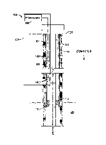
[0011] FIG. 1 is a schematic cross-sectional side view of an example well
system
100 including an optical communication system 105 in which two fiber optic
cables 124
and 126 have been coupled using a fiber optic coupling system 130. Fiber optic
cables
implemented in systems and environments other than a wellbore can also be
coupled
using the fiber optic coupling system 130. The well system 100 includes a
wellbore 114
that extends from a terranean surface 116 into one or more subterranean zones
120. A
tubing string 122 (for example, a production string, an injection string, a
drilling string or
other suitable type of working string) is inserted into the wellbore 114. The
tubing string
3

CA 02909934 2015-10-20
WO 2014/189639
PCT/US2014/034832
122 can carry a well tool 110 with which fiber optic cables can communicate.
In some
implementations, the wellbore 114 is lined with a casing or liner 118.
[0012] In an example configuration, the optical communication system 105 can
be installed between the tubing string 122 and the wellbore 114.
Alternatively, the optical
communication system 105 can be installed within the tubing string 122 or
within the
casing 118. In some implementations, the optical communication system 105 can
be
disposed in wireline tools carried on wires (e.g., wirelines, slicklines, or
other type of
wires). For example, each of the sensors and the fiber optic cables can be
included in a
wireline tool.
[0013] The optical communication system includes two or more fiber optic
cables
(e.g., a first fiber optic cable 124, a second fiber optic cable 126) to
optically
communicate light from an interrogator 106 to one or more targets and to
optically
communicate light from the targets back to the interrogator 106. An optical
sensor 140 is
an example of a target. Other examples of targets include any downhole source.
Examples of fiber optic couplings include E2000, FC/APC, splices between
dissimilar
fibers, fiber optic rotary joints (FORA subsea / down-hole wet-connects or dry-
connects,
and wellhead or subsea tree optical penetrators. In some implementations, the
target can
be a discrete point sensor or an array of discrete sensors. In some
implementations, the
target can be a distributed fiber sensor. For example, the continuous length
of the fiber
optic cable itself can be the sensor.
[0014] The interrogator 106 sends light to and receives light from the optical
sensor 140. The optical sensor 140 measures one or more physical properties
such as
temperature, strain, pressure, or other similar physical property. The one or
more targets
can also be carried on the wires that carry the wellbore tool 110. In
implementations in
which the continuous length of the fiber optic cable is the sensor, the sensor
signal is the
backscattered light returned by the fiber in case of Rayleigh, Brillouin, and
Raman
backscatter. The backscatter signals can be used to measure temperature
(Raman),
distributed acoustics (Rayleigh), strain (Brillouin) or combinations of them.
[0015] In some implementations, the first fiber optic cable 124 and the second
fiber optic cable 126 are connected to optically communicate light from the
interrogator
4

CA 02909934 2015-10-20
WO 2014/189639
PCT/US2014/034832
106 to the targets through a fiber optic coupling system 130. In general, the
fiber optic
coupling system 130 is applicable to any manner of two way communication on
fiber
within the wellbore. As discussed below, the fiber optic coupling system 130
can block
back reflection that may occur when coupling parts in the fiber optic coupling
system 130
interface the fiber optic cable 124 and the second optic cable 126.
[0016] FIG 2 is a schematic block diagram 200 of the interrogator 106
communicating with the optical sensor 140 through the fiber optic coupling
system 130.
Example components of the fiber optic coupling system 130 are illustrated in
FIG 3. The
interrogator 106 includes a light source 210, which can produce light
transmitted to the
optical sensor 140 through a connector 212 and the fiber optic coupling system
130. In
some implementations, components of the interrogator 106 can be included in a
first
housing that is disposed separately from a second housing that includes
components of
the fiber optic coupling system 130. The two housings can be optically coupled
to
communicate light from the interrogator 106 to a target (e.g., an optical
sensor 140)
through the fiber optic coupling system 130 and vice versa.
[0017] In an example light signal flow, light travels from the interrogator
106 to
the fiber optic coupling system 130 through a source-side fiber optic cable,
for example, a
first fiber optic cable 305 (FIG. 3). The fiber optic coupling system 130
includes a
source-side optical circulator 310 that communicates light to a source-side
portion 320 of
a source-to-target coupling part 321. In general, an optical circulator is a
non-reciprocal
optical device used to separate light signals that travel in opposite
directions in an optical
fiber. The circulator is a device including three ports arranged in a sequence
and
designed such that light signal entering a port exits from the next port in
the sequence.
That is, light signal entering a first port in the sequence is emitted from a
second port in
the sequence. But, if some of the emitted light is reflected back to the
circulator, the back
reflected light is not emitted out of the first port, but rather out of a
third port in the
sequence. In this manner, an optical circulator enables bi-directional
transmission of
light signals over a single optical fiber.
[0018] The source-side optical circulator 310 includes a fiber optic
input/output
311 (e.g., a bidirectional fiber optic port) that receives an incoming light
signal 301 from

CA 02909934 2015-10-20
WO 2014/189639
PCT/US2014/034832
the interrogator 106. The source-side optical circulator 310 transmits the
light received at
the fiber optic input/output 311 towards a fiber optic output 313 (e.g., a
unidirectional
fiber optic port). The fiber optic output 313 transmits the light toward the
source-side
portion 320 of the source-to-target coupling part 321 through a source-side
fiber optic
cable 306. The source-side optical circulator 310 is designed to not permit
block
transmission of light received at the fiber optic output 313 toward the fiber
optic
input/output 311. Consequently, the source-side optical circulator 310 blocks
(e.g., by
absorbing) all or most of back reflected light 351 that the source-side
optical circulator
310 receives from the source-side portion 320 of the source-to-target coupling
part 321 at
the fiber optic output 313. The source-side optical circulator 310 need not
block all of the
back reflected light 351 received at the fiber optic output 313. Instead, as
described
above, the source-side optical circulator 310 can block a specified threshold
of back
reflected sufficient for one or more components of the interrogator 106 to not
be
substantially negatively affected by a quantity of back reflected light that
is not blocked
by the source-side optical circulator 310. By blocking the back reflected
light, the
source-side optical circulator 310 mitigates (e.g., minimizes or eliminates)
back reflection
from the source-side portion 320 of the source-to-target coupling part 321.
[0019] The source-to-target coupling part 321 includes a target-side portion
322
that receives the light from the source-side portion 320. The target-side
portion 322 of
the source-to-target coupling part 321 communicates the received light to a
fiber optic
input 335 of a target-side optical circulator 330 through a target-side fiber
optic cable, for
example, a second fiber optic cable 307. The target-side optical circulator
330 can
transmit the light received at a second fiber optic input 335 (e.g., a
unidirectional fiber
optic port) toward a fiber optic input/output 331 (e.g., a bidirectional fiber
optic port).
The target-side optical circulator 330 transmits the light received at the
fiber optic
input/output 331 to a target, e.g., the optical sensor 140 (in FIG 2) as an
output signal
361.
[0020] The target (e.g., the optical sensor 140) returns a return signal 363
to the
target-side optical circulator 330 at the fiber optic input/output 331. The
return signal
363 includes communications (e.g., measurement values) generated at the
target. For
6

CA 02909934 2015-10-20
WO 2014/189639
PCT/US2014/034832
example, when implemented in a wellbore, the return signal 363 can be
modulated to
transmit the communications uphole to the interrogator 106. The target-side
optical
circulator 330 transmits the light received at the fiber optic input/output
331 towards a
fiber optic output 333 (e.g., a unidirectional fiber optic port), which, in
turn, transmits the
light toward a target-side portion 340 of a target-to-source coupling part 341
through
another target-side fiber optic cable 366.
[0021] A portion of the return signal 363 may be backscattered at the target-
side
portion 340 of the target-to-source coupling part 341 and travel to the fiber
optic output
333 as back reflected light 353. Similarly to the source-side optical
circulator 310, the
target-side optical circulator 330 is also designed to prevent transmission of
light received
at the fiber optic output 333 toward the fiber optic input/output 331.
Consequently, the
target-side optical circulator 330 blocks all or most of the back reflected
light 353. By
doing so, the target-side optical circulator 330 can avoid blinding a receiver
(e.g., a high-
gain receiver) used to pick up generally weak backscattered signals obtained
in
implementations in which the continuous length of the fiber is a sensor. The
non-
reflected portion of the return signal 363 continues to travel through the
source-side
portion 342 of the target-to-source coupling part 341 and through another
source-side
fiber optic cable 367 to enter the source-side optical circulator 310 at a
fiber optic input
315 (e.g., a unidirectional fiber optic port). The light then exits the source-
side optical
circulator 310 at the fiber optic input/output 311 as a return signal 303 that
travels
through the source-side fiber optic cable 305 to the interrogator 106 (as
shown in FIG 2).
[0022] The return signal 303 enters the interrogator 106 and reaches the
connector 212. The connector 212 transmits the return signal 303 to a detector
230. In
some implementations, the interrogator 106 includes an Erbium doped fiber
amplifier
(EDFA) 220 that receives the return signal 303 from the connector 220,
amplifies the
returned measurement signal 303, and transmits the amplified return signal to
the detector
230. Because back reflected light signals 351 and 353 are blocked by the first
and second
optical circulators 310 and 330, respectively, the back reflected light
signals 351 and 353
do not interfere with the return signal 303 transmitted back to the
interrogator 106.
Alternatively, a level of interference by the back reflected light signals
that are not
7

CA 02909934 2015-10-20
WO 2014/189639
PCT/US2014/034832
blocked is insufficient to substantially negatively affect the return signal
303 transmitted
back to the interrogator 106.
[0023] In some implementations, the source-side portion 320 and the target-
side
portion 322 of the source-to-target coupling part may include expanded beam
connections
to allow more light to be guided across the coupling interface of the source-
side and
target-side portions 320 and 322 in case of misalignment or contamination. For
example,
the source-to-target coupling part can be implemented at a wellhead that is
designed to
withstand high pressure. One option to pass fiber optic cables through the
wellhead is to
include a feed through. Doing so may compromise the ability of the wellhead to
withstand high pressures. An alternative option is to implement a transparent
material
(e.g., glass or ceramic), and to couple the source-side portion 320 and the
target-side
portion 322 on either side of the transparent material. Doing so can block
back reflection
through the transparent material disposed in the wellhead.
[0024] In some implementations, the second optical circulator 330 may not be
needed to block back reflection directed from the source-to-target coupling
part 321
toward the interrogator 106. In such situations, the implementation of the
target-to-
source optical circulator 330 may be to transmit light from the target toward
the
interrogator 106. Similarly, to block back reflection from the target-to-
source coupling
part 341 toward the target, the source-to-target fiber optical circulator 310
may not be
needed.
[0025] A number of implementations have been described. Nevertheless, it will
be understood that various modifications may be made without departing from
the spirit
and scope of the disclosure.
8

Dessin représentatif
Une figure unique qui représente un dessin illustrant l'invention.
États administratifs

2024-08-01 : Dans le cadre de la transition vers les Brevets de nouvelle génération (BNG), la base de données sur les brevets canadiens (BDBC) contient désormais un Historique d'événement plus détaillé, qui reproduit le Journal des événements de notre nouvelle solution interne.

Veuillez noter que les événements débutant par « Inactive : » se réfèrent à des événements qui ne sont plus utilisés dans notre nouvelle solution interne.

Pour une meilleure compréhension de l'état de la demande ou brevet qui figure sur cette page, la rubrique Mise en garde , et les descriptions de Brevet , Historique d'événement , Taxes périodiques et Historique des paiements devraient être consultées.

Historique d'événement

Description Date
Le délai pour l'annulation est expiré 2022-10-21
Lettre envoyée 2022-04-21
Lettre envoyée 2021-10-21
Lettre envoyée 2021-04-21
Représentant commun nommé 2019-10-30
Accordé par délivrance 2018-01-16
Inactive : Page couverture publiée 2018-01-15
Préoctroi 2017-11-30
Inactive : Taxe finale reçue 2017-11-30
Un avis d'acceptation est envoyé 2017-06-05
Lettre envoyée 2017-06-05
Un avis d'acceptation est envoyé 2017-06-05
Inactive : Approuvée aux fins d'acceptation (AFA) 2017-05-26
Inactive : QS réussi 2017-05-26
Modification reçue - modification volontaire 2017-01-13
Inactive : Dem. de l'examinateur par.30(2) Règles 2016-08-03
Inactive : Rapport - Aucun CQ 2016-07-31
Inactive : Acc. récept. de l'entrée phase nat. - RE 2015-10-29
Inactive : CIB attribuée 2015-10-29
Demande reçue - PCT 2015-10-29
Inactive : CIB en 1re position 2015-10-29
Lettre envoyée 2015-10-29
Exigences pour l'entrée dans la phase nationale - jugée conforme 2015-10-20
Exigences pour une requête d'examen - jugée conforme 2015-10-20
Toutes les exigences pour l'examen - jugée conforme 2015-10-20
Demande publiée (accessible au public) 2014-11-27

Historique d'abandonnement

Il n'y a pas d'historique d'abandonnement

Taxes périodiques

Le dernier paiement a été reçu le 2017-02-13

Avis : Si le paiement en totalité n'a pas été reçu au plus tard à la date indiquée, une taxe supplémentaire peut être imposée, soit une des taxes suivantes :

  • taxe de rétablissement ;
  • taxe pour paiement en souffrance ; ou
  • taxe additionnelle pour le renversement d'une péremption réputée.

Les taxes sur les brevets sont ajustées au 1er janvier de chaque année. Les montants ci-dessus sont les montants actuels s'ils sont reçus au plus tard le 31 décembre de l'année en cours.
Veuillez vous référer à la page web des taxes sur les brevets de l'OPIC pour voir tous les montants actuels des taxes.

Historique des taxes

Type de taxes Anniversaire Échéance Date payée
Taxe nationale de base - générale 2015-10-20
Requête d'examen - générale 2015-10-20
Enregistrement d'un document 2015-10-20
TM (demande, 2e anniv.) - générale 02 2016-04-21 2016-02-18
TM (demande, 3e anniv.) - générale 03 2017-04-21 2017-02-13
Taxe finale - générale 2017-11-30
TM (brevet, 4e anniv.) - générale 2018-04-23 2018-02-21
TM (brevet, 5e anniv.) - générale 2019-04-23 2019-02-15
TM (brevet, 6e anniv.) - générale 2020-04-21 2020-02-13
Titulaires au dossier

Les titulaires actuels et antérieures au dossier sont affichés en ordre alphabétique.

Titulaires actuels au dossier
HALLIBURTON ENERGY SERVICES, INC.
Titulaires antérieures au dossier
DAVID ANDREW BARFOOT
Les propriétaires antérieurs qui ne figurent pas dans la liste des « Propriétaires au dossier » apparaîtront dans d'autres documents au dossier.
Documents

Pour visionner les fichiers sélectionnés, entrer le code reCAPTCHA :


Pour visualiser une image, cliquer sur un lien dans la colonne description du document (Temporairement non-disponible). Pour télécharger l'image (les images), cliquer l'une ou plusieurs cases à cocher dans la première colonne et ensuite cliquer sur le bouton "Télécharger sélection en format PDF (archive Zip)" ou le bouton "Télécharger sélection (en un fichier PDF fusionné)".

Liste des documents de brevet publiés et non publiés sur la BDBC .

Si vous avez des difficultés à accéder au contenu, veuillez communiquer avec le Centre de services à la clientèle au 1-866-997-1936, ou envoyer un courriel au Centre de service à la clientèle de l'OPIC.

({010=Tous les documents, 020=Au moment du dépôt, 030=Au moment de la mise à la disponibilité du public, 040=À la délivrance, 050=Examen, 060=Correspondance reçue, 070=Divers, 080=Correspondance envoyée, 090=Paiement})


Description du
Document 
Date
(aaaa-mm-jj) 
Nombre de pages   Taille de l'image (Ko) 
Description 2015-10-19 8 432
Revendications 2015-10-19 4 170
Abrégé 2015-10-19 2 69
Dessin représentatif 2015-10-19 1 21
Dessins 2015-10-19 3 52
Revendications 2017-01-12 5 216
Dessin représentatif 2018-01-02 1 11
Accusé de réception de la requête d'examen 2015-10-28 1 175
Avis d'entree dans la phase nationale 2015-10-28 1 202
Courtoisie - Certificat d'enregistrement (document(s) connexe(s)) 2015-10-28 1 102
Rappel de taxe de maintien due 2015-12-21 1 111
Avis du commissaire - Demande jugée acceptable 2017-06-04 1 164
Avis du commissaire - Non-paiement de la taxe pour le maintien en état des droits conférés par un brevet 2021-06-01 1 558
Courtoisie - Brevet réputé périmé 2021-11-11 1 535
Avis du commissaire - Non-paiement de la taxe pour le maintien en état des droits conférés par un brevet 2022-06-01 1 551
Demande d'entrée en phase nationale 2015-10-19 11 432
Rapport de recherche internationale 2015-10-19 2 87
Déclaration 2015-10-19 2 47
Demande de l'examinateur 2016-08-02 4 191
Modification / réponse à un rapport 2017-01-12 27 1 183
Taxe finale 2017-11-29 2 67