Sélection de la langue

Search

Sommaire du brevet 2910118 

Énoncé de désistement de responsabilité concernant l'information provenant de tiers

Une partie des informations de ce site Web a été fournie par des sources externes. Le gouvernement du Canada n'assume aucune responsabilité concernant la précision, l'actualité ou la fiabilité des informations fournies par les sources externes. Les utilisateurs qui désirent employer cette information devraient consulter directement la source des informations. Le contenu fourni par les sources externes n'est pas assujetti aux exigences sur les langues officielles, la protection des renseignements personnels et l'accessibilité.

Disponibilité de l'Abrégé et des Revendications

L'apparition de différences dans le texte et l'image des Revendications et de l'Abrégé dépend du moment auquel le document est publié. Les textes des Revendications et de l'Abrégé sont affichés :

  • lorsque la demande peut être examinée par le public;
  • lorsque le brevet est émis (délivrance).
(12) Brevet: (11) CA 2910118
(54) Titre français: DISPOSITIF DE TIR DE MUNITIONS ENCARTOUCHEES
(54) Titre anglais: FIRING DEVICE FOR FIRING CARTRIDGE AMMUNITION
Statut: Accordé et délivré
Données bibliographiques
(51) Classification internationale des brevets (CIB):
  • F41A 09/58 (2006.01)
(72) Inventeurs :
  • MALTAN, JOHANNES (Allemagne)
  • KITTL, WOLFGANG (Allemagne)
  • KREBS, MICHAEL (Allemagne)
  • HUBER, FLORIAN (Allemagne)
(73) Titulaires :
  • RHEINMETALL WAFFE MUNITION GMBH
(71) Demandeurs :
  • RHEINMETALL WAFFE MUNITION GMBH (Allemagne)
(74) Agent: SMART & BIGGAR LP
(74) Co-agent:
(45) Délivré: 2020-08-25
(86) Date de dépôt PCT: 2014-03-10
(87) Mise à la disponibilité du public: 2014-10-02
Requête d'examen: 2018-07-31
Licence disponible: S.O.
Cédé au domaine public: S.O.
(25) Langue des documents déposés: Anglais

Traité de coopération en matière de brevets (PCT): Oui
(86) Numéro de la demande PCT: PCT/EP2014/054602
(87) Numéro de publication internationale PCT: EP2014054602
(85) Entrée nationale: 2015-10-23

(30) Données de priorité de la demande:
Numéro de la demande Pays / territoire Date
10 2013 005 378.1 (Allemagne) 2013-03-28

Abrégés

Abrégé français

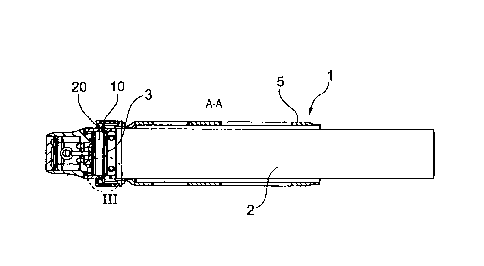
L'invention concerne un dispositif (1) de tir d'une munition encartouchée (2) qui comporte un culot (20) possédant au moins une empreinte périphérique (3) en forme de rainure sur sa circonférence extérieure. Selon l'invention, pour assurer le blocage de la munition (2) dans le dispositif de tir lors du chargement du dispositif de tir (1) côté embouchure, le dispositif de lancement (1) comporte une pièce de culot (4) et un système tubulaire de réception de munition (5) fixé à la pièce de culot (4), le système de réception de munition (5) étant monté mobile axialement sous la pression d'un élément de rappel (6) en direction de la pièce de fond (4). Selon l'invention, la pièce de culot (4) contient un élément de guidage annulaire (7) qui s'étend axialement jusque dans le système de réception de munition (5) et possède plusieurs orifices de guidage (9) qui s'étendent à travers la paroi (8) de l'élément de guidage (7) , chacune comportant un tracé orienté en biais depuis la face extérieure de l'élément de guidage (7) vers l'embouchure (12) du système de réception de munition (5). Dans les orifices de guidage (9), des éléments de verrouillage (10) sont montés mobiles et peuvent être sollicités par des éléments à ressort (11) sur leur côté opposé au système de réception de munition (5) de telle sorte que, lorsque le dispositif de tir (1) est chargé, les éléments de verrouillage (10) sont poussés par les éléments à ressort (11) dans l'empreinte (3) en forme de rainure de la munition (2). Pour décharger la munition (2), les éléments de verrouillage sont repoussés par le déplacement axial du système de réception de munition (5) en direction de la pièce de fond (4) hors de l'empreinte (3) en forme de rainure de la munition (2) jusque dans les orifices de guidage (9) de l'élément de guidage (7).


Abrégé anglais

The invention relates to a firing device (1) for firing cartridge ammunition (2) comprising a case head (20), which has on its outer circumference at least one peripheral, groove-shaped depression (3). In order to achieve secure arrestment of the ammunition (3) in the firing device (1) when the firing device (1) is loaded from the muzzle end, the invention proposes that the firing device (1) comprises a head piece (4) and a tubular ammunition-receiving device (5) that is secured on the front side of the head piece (4), wherein the ammunition-receiving device (5) is arranged such that it can be moved axially in the direction of the head piece (4) against the pressure of a restoring element (6). In this case, the head piece (4) includes an annular guiding element (7), which extends axially into the ammunition-receiving device (5) and has multiple guiding openings (9), which extend through the wall (8) of the guiding element (7) and are in each case of a form that is angled from the outer side of the guiding element (7) in the direction of the opening (12) of the ammunition-receiving device (5). Locking elements (10) are movably arranged in the guiding openings (9) and, on the side thereof that is facing away from the ammunition-receiving device (5) are acted upon by spring elements (11) in such a way that, when the firing device (1) is loaded, the locking elements (10) are pressed by the spring elements (11) into the groove-shaped depression (3) in the ammunition (2). For unloading the ammunition (2), the locking elements are pressed out from the groove-shaped depression (3) in the ammunition (2) into the guiding openings (9) of the guiding element (7) by axially moving the ammunition-receiving device (5) towards the head piece (4).

Revendications

Note : Les revendications sont présentées dans la langue officielle dans laquelle elles ont été soumises.


6
CLAIMS:
1. A firing device for firing cartridge ammunition with a case head, having on
its outer
circumference at least one circumferential, groove-shaped depression, the
firing device
comprising a head piece and a tubular ammunition receiving-device fixed front-
side at the
head piece; wherein the ammunition receiving-device is slidably mounted
against the
pressure of a restoring element, axially in the direction of the head piece;
and wherein the
head piece includes an annular guiding element, which axially extends into the
ammunition
receiving-device, such that when the firing device is loaded, the groove-
shaped depression of
the ammunition is at least partially enclosed by the annular guiding element.
2. A firing device according to claim 1, wherein the annular guiding element
includes multiple
guiding openings, in each of which a locking element is slidably disposed, and
which are
arranged distributed over the periphery and which extend through the wall of
the guiding
element.
3. A firing device according to claim 2, wherein the guiding openings each
feature a course
that is obliquely directed from the outside of the guiding element to the
muzzle of the
ammunition receiving-device.
4. A firing device according to claim 2 or 3, wherein the locking elements are
acted upon by
spring elements, on the side facing away from the ammunition receiving-device,
such that
when the firing device is loaded, the locking elements of the spring elements
are pressed into
the groove-shaped depression of the munition.
5. A firing device according to claim 4, wherein the spring elements acting on
the locking
elements are wave springs.
6. A firing device according to any one of claims 2 to 5, wherein the locking
elements are
displaceably arranged by the ammunition receiving-device in such a way that
upon an axial
displacement of the ammunition receiving-device in the direction of the head
piece, the
locking elements are slidable against the pressure of spring elements from the
groove-
shaped depression of the ammunition into the guiding openings of the guiding
element, so
that when the firing device is loaded, the locking of the munitions is lifted
by the locking
elements.

7
7. A firing device according to any one of claims 2 to 6, wherein the locking
elements are pin-
shaped.
8. A firing device according to claim 7, wherein the locking elements are
configured as
cylindrical pins.
9. A firing device according to any one of claims 1 to 8, wherein the head
piece and the
ammunition receiving-device are detachably interconnected.
10. A firing device according to claim 9, wherein the head piece and the
ammunition
receiving-device are interconnected via a bayonet connection.
11. A firing device according to any one of claims 1 to 10, wherein the
restoring element is a
spring.

Description

Note : Les descriptions sont présentées dans la langue officielle dans laquelle elles ont été soumises.


CA 02910118 2015-10-23
WO 2014/154473 Al 1 PCT/EP2014/054602
DESCRIPTION
Firing Device for Firing Cartridge Ammunition
The invention relates to a firing device or a launcher for firing cartridge
ammunition, with a case head,
which has on its outer circumference at least one peripheral, groove-like
depression, but with the priority
of receiving and arresting the ammunition in the firing device. Particularly
in firing devices, such as
grenade launchers, in which the ammunition is loaded into the weapon from the
front, i.e. from the
muzzle, the problem is often that the ammunition cannot be reliably arrested
and that movements of the
grenade launcher (e.g. vibration or shock stresses [sic]) can move it axially
within the barrel.
To securely arrest the ammunition after loading the weapon, these firing
devices are partially structured
such that the respective ammunition is not loaded from the front but instead
from the sides or the rear,
into the respective mortars, and then also arrested by a locking device. Such
loading and locking devices,
however, are associated with a relatively space-consuming and costly
construction of the respective
weapon.
From DE 10 2011 050 685 Al, such a weapon with a straightening device and a
method of operating the
weapon are known. Here, the magazine is arranged in front of the muzzle end of
a gun barrel.
DE 692 16 185 T2 (EP 0532721 B1) describes a mortar with a drum magazine. Both
DE 10 2005 0 6
879 Al and DE 10 2005 006 062 Al feature devices for unloading a mortar
cartridge. The object of the
invention is to disclose a firing device, especially for firing launcher
ammunition, with which the loading of
ammunition via the muzzle of the respective weapon is possible, wherein after
loading, the ammunition
can be securely arrested in the firing device as well as easily unloaded from
the firing device.
This object is achieved by the features of claim 1. Further, particularly
advantageous embodiments of the
invention are disclosed in the dependent claims.
From DE 20 2012 008 824 111, a firing device with an ammunition locking
mechanism is known, in which
in particular the removal of ammunition from the magazine takes place without
application of force on the
ammunition. Accordingly, a threaded sleeve of the fastening and securing
device is pulled backwards,
= which in turn acts on a washer that guides a cylindrical pin upwards in a
groove and thereby frees the
entire pipe diameter for unloading or loading. A wave spring keeps the
cylindrical pin in position. This
design allows for the loading and unloading of munitions from the muzzle side
of the weapon.

,
81791941
2
The present invention is in turn mainly based on the idea that the firing
device comprises a head piece
and a tubular ammunition receiving-device which is fastened to the front of
the head piece and forms the
barrel. This ammunition receiving-device is movably disposed against the
pressure of a restoring
element, axially in the direction of the head piece. In this case, the head
piece has an annular guiding
element which extends axially into the ammunition receiving-device and
contains several guiding
openings which are arranged distributed over the circumference and extend
through the wall of the
guiding element The guiding openings each feature an obliquely directed path
from the outside of the
guiding element towards the muzzle of the ammunition receiving-device. In the
respective guiding
opening, a locking element is slidably disposed and is acted upon by a spring
element on the side facing
away from the ammunition receiving-device, such that when the firing device is
loaded, the locking
elements are pressed by the spring elements into the groove-shaped depression
of the ammunition. In
addition, the locking elements are displaceably arranged by the ammunition
receiving-device, in such a
way that upon an axial displacement of the ammunition receiving-device in the
direction of the head
piece, the locking elements are pushed from the groove-shaped depression of
the ammunition into the
guiding openings of the guiding element against the pressure of the spring
elements, and that with a
loaded firing device, the arresting of the ammunition is canceled by the
locking elements, so that the
ammunition can be discharged on the muzzle side. When unloading the
ammunition, the locking
elements are thus pushed into the guiding openings of the guiding element
through axial displacement of
the ammunition receiving-device towards the head piece and out of the groove-
shaped depression of
ammunition.
The launching device of the invention offers, among other things, the
advantage that the ammunition
locking mechanism requires only minimal installation and operating space. In
addition, the recoil forces
that occur during firing act upon the head piece of the firing device without
mechanically stressing the
actual locking mechanism.
Preferably, the head piece and the ammunition receiving-device can be
detachably interconnected with
one another, for example by means of a bayonet joint This makes it easy to
mount or dismantle the firing
device.
The locking elements may be, for example, pin-shaped locking elements, in
particular cylindrical pins,
which are acted upon, for example, by spring elements designed as wave
springs.
CA 2910118 2020-01-16

,
81791941
2a
According to an embodiment, there is provided a firing device for firing
cartridge ammunition
with a case head, having on its outer circumference at least one
circumferential, groove-
shaped depression, the firing device comprising a head piece and a tubular
ammunition
receiving-device fixed front-side at the head piece; wherein the ammunition
receiving-device
.. is slidably mounted against the pressure of a restoring element, axially in
the direction of the
head piece; and wherein the head piece includes an annular guiding element,
which axially
extends into the ammunition receiving-device, such that when the firing device
is loaded, the
groove-shaped depression of the ammunition is at least partially enclosed by
the annular
guiding element.
Further details and advantages of the invention will become apparent from the
following,
explained in the exemplary embodiments with reference to the figures.
Shown are:
CA 2910118 2020-01-16

CA 02910118 2015-10-23
3
Fig. 1 shows the side view of a firing device according to the invention,
loaded with ammunition;
Fig. 2 is a longitudinal cross-section along the intersection line, labeled as
11-11 in Fig. 1, and
Fig. 3 is an enlarged view of the section, identified in Fig. 2 as III;
Fig. 4 is a perspective view of the arresting device of the firing device.
In fig. 1 and 2, a launching device according to the invention is denoted by
1, which is a firing device or a
weapon launch system, etc., for firing cartridge ammunition, for example,
pyrotechnic ammunition 2 (also
submunitions with effective masses). On its rear side, the ammunition 2 has a
case head 20 with at least
one, groove-shaped depression 3, revolving on its outer circumference.
The firing device 1 comprises a head piece 4 and a tubular ammunition
receiving-device 5, which is
attached to the head piece 4 by its front side. The head piece 4 and the
ammunition receiving-device 5
are detachably interconnected via a connection 14, preferably a bayonet
connection. The ammunition
receiving-device 5 is in turn slidably and axially disposed in the direction
of the head piece 4 against the
pressure of a spring 6, which is indicated in Fig. 1 by an arrow 100.
The head piece 4 comprises an annular guiding element 7 (Fig. 3), which
axially extends into the
ammunition receiving-device 5, such that the groove-shaped depression 3 of the
ammunition 2 is at least
partially enclosed by the annular guiding element 7 after loading.
The annular guiding element 7 preferably contains two openings 9 which are
uniformly and laterally
disposed on the circumference and extend transversely through the wall 8 (Fig.
4) of the guiding element
7. In this exemplary embodiment, the openings 9 extend obliquely rearward to
the head piece 4.
Each opening 9 of the guiding element 7 serves for receiving a cylindrical pin
10 which is slidably
integrated along the sloped path toward the head piece 4. These cylindrical
pins 10 are acted upon by a
wave spring 11 that is integrated in the guiding element 7 (Fig. 4), such that
during loading, the cylindrical
pins 10 are pressed by the wave spring 11 into the openings 9 and thus into
the groove-shaped
depression 3 of the ammunition 2, thereby locking the munition into position.
The wave spring 11 thereby
is supported by a movable ring 15, which abuts the cylindrical pins 10.
The cylindrical pins 10 can be displaced by the ammunition receiving-device 5,
such that when an axial
displacement of the ammunition receiving-device 5 against the pressure of the
wave springs 11, 12, in the

CA 02910118 2015-10-23
4
direction of the arrow 100 (i.e. toward the head piece 4) takes place, the
cylinder pins 10 are moved out
from the groove-shaped depression 3 of the ammunition 2 into the guiding
openings 9 of the guiding
element 7, so that the locking of the ammunition 2 is lifted by the cylinder
pins 10, and the ammunition 2
can be discharged.
The procedure is as follows:
For loading or loading up the firing device 1, the pyrotechnic ammunition 2 is
inserted into the muzzle 12
of the ammunition receiving-device 5. By pushing the ammunition 2 into the
ammunition receiving-device
6, the front edge-side portion 21 of the case head 20 of the ammunition 2
reaches the cylindrical pins 10
protruding into the loading area 13 of the firing device 1. These are then
pushed against the pressure of
the wave springs 11, 12 into the guiding openings 9 of the guiding elements 7,
so that the ammunition
can be axially pushed further into the firing device 1 until the cylindrical
pins 10 engage in the groove-
shaped depression 3 of the ammunition and arrest the ammunition 2 in the
firing device 1. The guiding
element 7 and the wave spring 11 then prevent the ammunition 2 from moving
towards the muzzle 12 of
the ammunition receiving-device 5.
To unload the ammunition 2, the ammunition receiving-device 5 is pressed in
the direction of the arrow
100. This urges both the spring 6 and the cylindrical pins 10 axially toward
the head piece 4. The guiding
openings 9 of the guiding element 7 then guide the cylindrical pins 10
outwards, so that the arresting of
the ammunition 2 is canceled and discharge on the muzzle side can be achieved.
LIST OF REFERENCE NUMBERS
1 firing device, grenade launcher
2 (pyrotechnic) ammunition
3 groove-shaped depression
4 head piece
ammunition receiving-device
6 restoring element, spring
7 guiding element
8 wall
9 guiding opening
(pin-shaped) locking element, cylindrical pin
11 spring element, wave spring
12 muzzle
13 loading area

CA 02910118 2015-10-23
14 connection
ring (support for wave spring)
case head
21 edge-side area
100 arrow

Dessin représentatif
Une figure unique qui représente un dessin illustrant l'invention.
États administratifs

2024-08-01 : Dans le cadre de la transition vers les Brevets de nouvelle génération (BNG), la base de données sur les brevets canadiens (BDBC) contient désormais un Historique d'événement plus détaillé, qui reproduit le Journal des événements de notre nouvelle solution interne.

Veuillez noter que les événements débutant par « Inactive : » se réfèrent à des événements qui ne sont plus utilisés dans notre nouvelle solution interne.

Pour une meilleure compréhension de l'état de la demande ou brevet qui figure sur cette page, la rubrique Mise en garde , et les descriptions de Brevet , Historique d'événement , Taxes périodiques et Historique des paiements devraient être consultées.

Historique d'événement

Description Date
Représentant commun nommé 2020-11-07
Accordé par délivrance 2020-08-25
Inactive : Page couverture publiée 2020-08-24
Inactive : COVID 19 - Délai prolongé 2020-07-16
Inactive : COVID 19 - Délai prolongé 2020-07-02
Inactive : Taxe finale reçue 2020-06-11
Préoctroi 2020-06-11
Inactive : COVID 19 - Délai prolongé 2020-06-10
Un avis d'acceptation est envoyé 2020-02-20
Lettre envoyée 2020-02-20
Un avis d'acceptation est envoyé 2020-02-20
Inactive : Approuvée aux fins d'acceptation (AFA) 2020-02-04
Inactive : Q2 réussi 2020-02-04
Modification reçue - modification volontaire 2020-01-16
Représentant commun nommé 2019-10-30
Inactive : Dem. de l'examinateur par.30(2) Règles 2019-07-16
Inactive : Rapport - Aucun CQ 2019-07-15
Lettre envoyée 2018-08-02
Toutes les exigences pour l'examen - jugée conforme 2018-07-31
Exigences pour une requête d'examen - jugée conforme 2018-07-31
Requête d'examen reçue 2018-07-31
Inactive : CIB en 1re position 2015-10-30
Inactive : Notice - Entrée phase nat. - Pas de RE 2015-10-30
Inactive : CIB attribuée 2015-10-30
Demande reçue - PCT 2015-10-30
Exigences pour l'entrée dans la phase nationale - jugée conforme 2015-10-23
Demande publiée (accessible au public) 2014-10-02

Historique d'abandonnement

Il n'y a pas d'historique d'abandonnement

Taxes périodiques

Le dernier paiement a été reçu le 2020-03-02

Avis : Si le paiement en totalité n'a pas été reçu au plus tard à la date indiquée, une taxe supplémentaire peut être imposée, soit une des taxes suivantes :

  • taxe de rétablissement ;
  • taxe pour paiement en souffrance ; ou
  • taxe additionnelle pour le renversement d'une péremption réputée.

Les taxes sur les brevets sont ajustées au 1er janvier de chaque année. Les montants ci-dessus sont les montants actuels s'ils sont reçus au plus tard le 31 décembre de l'année en cours.
Veuillez vous référer à la page web des taxes sur les brevets de l'OPIC pour voir tous les montants actuels des taxes.

Historique des taxes

Type de taxes Anniversaire Échéance Date payée
Rétablissement (phase nationale) 2015-10-23
Taxe nationale de base - générale 2015-10-23
TM (demande, 2e anniv.) - générale 02 2016-03-10 2016-02-22
TM (demande, 3e anniv.) - générale 03 2017-03-10 2017-02-17
TM (demande, 4e anniv.) - générale 04 2018-03-12 2018-02-22
Requête d'examen - générale 2018-07-31
TM (demande, 5e anniv.) - générale 05 2019-03-11 2019-02-22
TM (demande, 6e anniv.) - générale 06 2020-03-10 2020-03-02
Taxe finale - générale 2020-06-22 2020-06-11
TM (brevet, 7e anniv.) - générale 2021-03-10 2021-03-01
TM (brevet, 8e anniv.) - générale 2022-03-10 2022-02-28
TM (brevet, 9e anniv.) - générale 2023-03-10 2023-02-27
TM (brevet, 10e anniv.) - générale 2024-03-11 2024-02-26
Titulaires au dossier

Les titulaires actuels et antérieures au dossier sont affichés en ordre alphabétique.

Titulaires actuels au dossier
RHEINMETALL WAFFE MUNITION GMBH
Titulaires antérieures au dossier
FLORIAN HUBER
JOHANNES MALTAN
MICHAEL KREBS
WOLFGANG KITTL
Les propriétaires antérieurs qui ne figurent pas dans la liste des « Propriétaires au dossier » apparaîtront dans d'autres documents au dossier.
Documents

Pour visionner les fichiers sélectionnés, entrer le code reCAPTCHA :


Pour visualiser une image, cliquer sur un lien dans la colonne description du document. Pour télécharger l'image (les images), cliquer l'une ou plusieurs cases à cocher dans la première colonne et ensuite cliquer sur le bouton "Télécharger sélection en format PDF (archive Zip)" ou le bouton "Télécharger sélection (en un fichier PDF fusionné)".

Liste des documents de brevet publiés et non publiés sur la BDBC .

Si vous avez des difficultés à accéder au contenu, veuillez communiquer avec le Centre de services à la clientèle au 1-866-997-1936, ou envoyer un courriel au Centre de service à la clientèle de l'OPIC.


Description du
Document 
Date
(aaaa-mm-jj) 
Nombre de pages   Taille de l'image (Ko) 
Description 2015-10-22 5 200
Dessin représentatif 2015-10-22 1 5
Dessins 2015-10-22 2 36
Abrégé 2015-10-22 1 41
Revendications 2015-10-22 2 64
Description 2020-01-15 6 218
Revendications 2020-01-15 2 60
Dessin représentatif 2020-07-29 1 5
Paiement de taxe périodique 2024-02-25 23 944
Rappel de taxe de maintien due 2015-11-11 1 111
Avis d'entree dans la phase nationale 2015-10-29 1 193
Accusé de réception de la requête d'examen 2018-08-01 1 175
Avis du commissaire - Demande jugée acceptable 2020-02-19 1 503
Requête d'examen 2018-07-30 2 67
Rapport de recherche internationale 2015-10-22 24 715
Traité de coopération en matière de brevets (PCT) 2015-10-22 2 112
Modification - Abrégé 2015-10-22 2 121
Demande d'entrée en phase nationale 2015-10-22 3 74
Demande de l'examinateur 2019-07-15 3 154
Modification / réponse à un rapport 2020-01-15 10 361
Taxe finale 2020-06-10 5 132