Note : Les descriptions sont présentées dans la langue officielle dans laquelle elles ont été soumises.
CA 02910435 2015-10-27
WO 2014/182509 PCT/US2014/035970
1
ELECTROMECHANICAL CYLINDER LOCK WITH KEY OVERRIDE
FIELD OF THE INVENTION
The present invention relates generally to cylinder lock assemblies, and
particularly to
an electromechanical cylinder lock with different modes of operation,
including actuator
operation and knob operation.
BACKGROUND OF THE INVENTION
Double cylinder locks are well known, which may be locked and unlocked from
opposite sides of a door or window. A typical double cylinder assembly, such
as a Euro
profile cylinder, includes a cylinder body adapted to be mounted transversely
through a lock
case. The body typically has two rotatable pin plugs, and a central rotatable
cam (also
referred to as a thrower) for extending and retracting one or more locking
bolts in the door
lock. Insertion of a proper key into either plug allows actuation of the cam.
In an alternative form, one of the cylinder mechanisms is replaced by a shaft
equipped
with a knob or the like which can be turned freely by hand to permit operation
of the bolt
from one side without a key.
In another alternative form, the cylinder lock is actuatable by means of some
actuator,
such as an electromechanical lock which may be actuatable by means of a drive
motor (e.g., a
gear motor).
The drive motor is typically mounted in an escutcheon on an inner face of the
door or
on some internal part of the door. The drive motor has a driveshaft for
transmitting rotation to
the cylinder lock, typically to a shaft extending from the cylinder lock. When
the drive motor
is electrically energized, it causes actuation (e.g., rotation) of the cam to
open or close the
locking bolts. The drive motor is typically energized by a transponder in a
key or other
device.
SUMMARY OF THE INVENTION
The present invention seeks to provide an improved electromechanical cylinder
lock
with different modes of operation, including actuator operation and manual
(e.g., knob)
operation (and in some embodiments, mechanical key override operation), as
described more
in detail hereinbelow.
There is thus provided in accordance with an embodiment of the present
invention a
cylinder lock including a cylinder lock body including a cam, an actuator and
a manual
CA 02910435 2015-10-27
WO 2014/182509 PCT/US2014/035970
2
element for operating the cam, and a clutch contained in the cylinder lock
body that is
selectively engaged with the cam and with either of the actuator and the
manual element, and
a coupler contained in the cylinder lock body, wherein suitable movement of
the coupler
engages the manual element with the clutch.
In accordance with an embodiment of the present invention, a key-operated pin
plug
is disposed in the cylinder lock body in which a key is insertable for turning
the plug and
throwing the cam.
In accordance with an embodiment of the present invention, an overpowering
device
is contained in the cylinder lock body operative to couple the key-operated
pin plug with the
cam and decouple the actuator and the manual element from operating the cam.
In accordance with an embodiment of the present invention, when the key is
fully
inserted in a keyway of the key-operated pin plug, the overpowering device
engages a plug
coupler with the cam so as to engage the plug with the cam.
In accordance with an embodiment of the present invention, the manual element
is
connected to an outer shaft which has a distal face arranged to selectively
engage and
disengage with the coupler.
In accordance with an embodiment of the present invention, the actuator has a
drive
shaft, whose distal end is received in a proximal end of a length-adapter,
which has a distal
end received in a proximal end of the clutch.
In accordance with an embodiment of the present invention, the drive shaft is
slidingly engaged with the length-adapter, and the length-adapter is slidingly
engaged with
the clutch.
BRIEF DESCRIPTION OF THE DRAWINGS
The present invention will be understood and appreciated more fully from the
following detailed description, taken in conjunction with the drawings in
which:
Fig. 1 is a simplified pictorial illustration of a cylinder lock, constructed
and operative
in accordance with a non-limiting embodiment of the present invention;
Fig. 1A is a simplified illustration of the cylinder lock, showing possible
modes of
cam operation, including actuator, manual element and key-operated actuation;
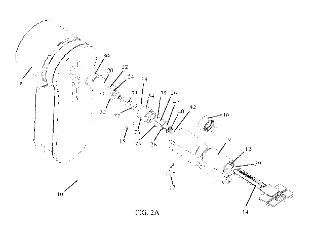
Figs. 2A and 2B are simplified exploded illustrations of the cylinder lock of
Fig. 1;
CA 02910435 2015-10-27
WO 2014/182509 PCT/US2014/035970
3
Fig. 3 is a simplified pictorial illustration of a reduction gear, constructed
and
operative in accordance with an embodiment of the present invention, wherein
the reduction
is operatively linked to the actuator of Fig. 1;
Fig. 4 is a simplified side view of the reduction gear of Fig. 3;
Fig. 4A is a simplified sectional view of the reduction gear of Fig. 4, taken
along lines
A-A in Fig. 4;
Fig. 4B is a simplified sectional view of the reduction gear of Fig. 4, taken
along lines
B-B in Fig. 4A;
Fig. 4C is a simplified sectional view of the reduction gear of Fig. 4, taken
along lines
C-C in Fig. 4A; and
Figs. 5A-5F are simplified illustrations of the inner gear of the reduction
gear
translating and causing rotation of the outer gear, in accordance with an
embodiment of the
present invention.
DETAILED DESCRIPTION OF EMBODIMENTS
Reference is now made to Fig. 1, which illustrates a cylinder lock 10,
constructed and
operative in accordance with a non-limiting embodiment of the present
invention. Cylinder
lock 10 is shown as having a Euro profile, but the invention is not limited to
this
configuration. Cylinder lock 10 includes a body 9 in which there is a key-
operated pin plug
12 in which a key 14 (Figs. 1A, 2A-2B) may be inserted for turning the plug 12
and throwing
(which means actuating, such as by turning, but could also be a linear motion)
a cam 16 (e.g.,
tongue or lever) (Figs. 1A, 2A-2B). Cylinder lock 10 also includes a manual
element 18 (also
referred to as knob or handle 18) and an actuator 20 (Figs. 1A, 2A-2B) for
throwing cam 16,
as will be explained further below.
Reference is now made to Fig. 1A, which illustrates possible modes of cam
operation,
including actuator, manual element and key-operated actuation. This is a
simplified overview
of operation and a more detailed description of each mode will be provided
below. The
elements shown in Fig. 1A are also shown in Figs. 2A-2B.
A clutch 26 is contained in cylinder lock body 9 that selectively engages cam
16 with
either of actuator 20 and manual element 18. (In other words, clutch 26 is not
external to
body 9.) In the actuator operation, a drive shaft 22 of actuator 20 is engaged
with clutch 26,
either directly, or as shown in the drawing, via a length-adapter 23, whose
distal end is
CA 02910435 2015-10-27
WO 2014/182509 PCT/US2014/035970
4
received in clutch 26. Since clutch 26 is engaged with cam 16, the rotation of
drive shaft 22
actuates cam 16.
Manual element 18 can be turned to rotate drive shaft 22. For example, manual
element 18 can be a housing of the actuator 20, which serves as a turning
handle; manual
element 18 simply involves grasping the housing and turning it to rotate drive
shaft 22. In
addition, manual element 18 can be linked with clutch 26 independently of
actuator 20.
Manual element 18 may be attached to an outer shaft 30, which can engage a
coupler 34,
such as by means of one or more apertures 27 mating with one or more spring-
loaded pins 19
disposed in coupler 34. Coupler 34 engages clutch 26. In the manual operation,
turning
manual element 18 rotates outer shaft 30, which when coupled to coupler 34,
causes clutch
26 to throw cam 16. As will be described later, irrespective of any angular
orientation of
actuator 20 with respect to clutch 26, manual element 18 can engage clutch 26
by suitable
movement of coupler 34.
In the key operation, key-operated pin plug 12 is disposed in the cylinder
lock body 9
in which key 14 is insertable for turning the plug 12, which in turn rotates a
plug coupler 47
that engages and throws cam 16. As will be described later, an overpowering
device 42 is
contained in the cylinder lock body 9 operative to couple the key-operated pin
plug 12 with
the cam 16 and decouple the actuator 20 and the manual element 18 from
operating the cam
16. Alternatively, plug 12 can be turned by other means than a key, such as by
a motor which
is operated by a transponder, for example.
The mode of operation wherein actuator 20 actuates cam 16 is now explained
with
reference to Figs. 1A, 2A and 2B. Actuator 20 has a drive shaft 22, whose
distal end 24
engages a proximal end of a length-adapter 23, whose distal end is received in
a proximal end
25 of clutch 26 contained in body 9. Cam 16 may be assembled in body 9 with a
circlips 17.
Clutch 26 has a distal tooth 28 (Fig. 2A) that engages cam 16. (For example,
tooth 28 may
enter and push against a recess 29 formed in cam 16, shown in Fig. 2B.) The
engagements of
drive shaft 22 with length-adapter 23 and of length-adapter 23 with clutch 26
may be
accomplished by any suitable means, such as but not limited to, splines,
teeth, or other
suitable engagement. In the illustrated embodiment in Fig. 2A, a pin 15 enters
an elongate
hole 73 formed in coupler 34 and an elongate hole 75 formed in clutch 26 and a
hole 77
formed in length-adapter 23. The engagements of drive shaft 22 with length-
adapter 23, and
CA 02910435 2015-10-27
WO 2014/182509 PCT/US2014/035970
of length-adapter 23 with clutch 26, may permit sliding between the parts. As
will be
explained later, the distal tooth 28 of clutch 26 can be moved out of
engagement with cam
16.
The mode of operation wherein manual element (knob) 18 actuates cam 16 is now
explained with reference to Figs. 1A, 2A and 2B. As seen in Figs. 2A-2B, one
or more
apertures 27 are formed on a distal face 32 of shaft 22. One or more spring-
loaded pins 19 are
mounted on the proximal end of coupler 34. When it is desired to operate the
cylinder lock
with knob 18, knob 18 is pushed inwards in the direction of coupler 34. If pin
19 is not
aligned with aperture 27, knob 18 is turned until pin 19 does align with
aperture 27. Due to
the spring-loading of pin 19, pin 19 juts into aperture 27, thereby effecting
engagement of
knob 18 with coupler 34. Since coupler 34 engages clutch 26, knob 18 is now
mechanically
engaged with clutch 26 and can be used to turn clutch 26 and throw cam 16,
just as described
for the actuator 20.
It is noted that knob 18 can engage clutch 26 via coupler 34 no matter what
the
angular orientation of actuator 20 is with respect to clutch 26. Thus, even if
the actuator 20 is
engaged with clutch 26 to operate cam 16, and all of a sudden has some failure
so that it
cannot throw cam 16 despite being engaged with clutch 26, knob 18 can be
pushed to engage
clutch 26 via coupler 34, thereby overriding the actuator engagement. This can
be useful to
prevent a person from getting locked inside a room.
The mode of operation wherein key 14 actuates cam 16 is now explained with
reference to Figs. 1A, 2A and 2B. When key 14 is initially inserted in a
keyway 39 (Figs. 2A-
2B), clutch 26 is still engaged for actuator or knob operation, because distal
tooth 28 of
clutch 26 is still engaged with cam 16.
In one embodiment, after key 14 has been fully inserted in keyway 39, key 14
presses
against a plunger 42 (also called overpowering device 42), which presses
against, and is
strong enough to overcome, engagement of clutch 26 with cam 16. Overpowering
device 42
includes a biasing device 40 (e.g., a coil spring placed underneath the head
of plunger 42).
With key 14 fully inserted, the biasing force of biasing device 40 causes
clutch 26 to turn so
that distal tooth 28 (Fig. 2A) of clutch 26 becomes disengaged with cam 16.
Referring to Fig.
2B, this means that tooth 28, which abuts against recess 29 in cam 16, turns
so that it no
longer abuts against recess 29. The biasing force of biasing device 40 then
immediately
CA 02910435 2015-10-27
WO 2014/182509 PCT/US2014/035970
6
causes clutch 26 to move outwards, so that distal tooth 28 of clutch 26
becomes disengaged
with cam 16.
In addition to the disengagement of clutch 26 associated with the actuator or
knob
operation, the biasing force of biasing device 40 urges plug coupler 47 into
engagement with
cam 16. Now that plug coupler 47 engages cam 16, turning key 14 will operate
cam 16.
Even if someone were to try to force engagement from the knob/actuator side
with
clutch 26 in an attempt to operate cam 16, such as by pushing outer shaft 30
or drive shaft 22
towards clutch 26, the biasing device 40 is stronger and prevents length-
adapter 23 from
engaging clutch 26, so that key 14 remains as the only operator of the
cylinder lock. This
may be of particular importance for allowing someone to enter a room where the
occupant
has become unable to operate the lock from within the room (e.g., the occupant
is weak, has
fainted, etc.).
Reference is now made to Figs. 3-4C, which illustrate an embodiment in which
the
actuator is a reduction gear disposed at least partially inside the cylinder
lock, in accordance
with a non-limiting embodiment of the present invention. The actuator is based
on the
description in PCT Patent Application PCT/US13/24837.
In the illustrated embodiment, a reduction gear 110 includes an inner gear 112
and an
outer gear 114. Outer gear 114 is arranged for rotation about a rotation axis
116. Outer gear
114 is journaled in a housing 118 and has an output shaft 120 that extends
outwards from
housing 118. The bearing surface is preferably the output shaft 120 rotating
in a hole 121
formed in housing 118 (with optional bearing elements or lubrication material,
for example)
or the outer contour of the outer gear 114 rotating in housing 118 (with
optional bearing
elements or lubrication material, for example).
Inner and outer gears 112 and 114 are mounted on a shaft 122, which rotates
about
rotation axis 116. However, in contrast to outer gear 114, inner gear 112 is
arranged for
translational movement and does not rotate. Shaft 122 includes an eccentric
member 124
which is eccentric to rotation axis 116 (eccentricity E shown in Fig. 4A).
During rotation of
shaft 122 about rotation axis 116, eccentric member 124 causes inner gear 112
to move in the
translational movement. During its translational movement, inner gear 112
meshes with outer
gear 114 and causes outer gear 114 to rotate about rotation axis 116, as will
be explained
more in detail below.
CA 02910435 2015-10-27
WO 2014/182509 PCT/US2014/035970
7
A limiter 126 is provided that constrains the translational movement of inner
gear 112
within defined limits. The limiter 126 does not extend beyond the outer teeth
of inner gear
112, which is one of the reasons reduction gear 110 is such a compact
assembly.
In the illustrated embodiment, limiter 126 is a straight-sided member that
extends
axially from inner gear 112. Limiter 126 is shown as having four sides, which
is considered
an optimal number, but the invention is not in any way limited to this
configuration. Limiter
126 and inner gear 112 have a common through hole 128 for mounting on shaft
122. Through
hole 128 is large enough to accommodate the movement of eccentric member 124,
and is
thus oversized compared to the outer diameter of the shaft 122.
Limiter 126 is arranged for movement in an inner periphery of a first boundary
member 130. First boundary member 130 has straight-sided inner and outer
contours. The
inner contour accommodates the shape of limiter 126 but is larger than the
outer contour of
limiter 126 to allow for linear movement of limiter 126 therein.
First boundary member 130 is arranged for movement in an inner periphery of a
second boundary member 132. First and second boundary members 130 and 132 are
mounted
on shaft 122 as well. As seen best in Fig. 4A, shaft 122 is journaled in a
mounting hole 134
formed in second boundary member 132 (with optional bearing elements or
lubrication
material, for example). The portion of shaft 122 that extends outwards of
second boundary
member 132 is an interface member for connection to an actuator (e.g., a
servomotor and the
like, not shown) for movement of the reduction gear 110.
A counterweight 136 may be mounted on shaft 122 for balancing with the
eccentric
member 124.
Reference is now made to Figs. 5A-5F, which illustrate inner gear 112
translating and
causing rotation of outer gear 114, in accordance with an embodiment of the
present
invention.
The reference axes are X0 and Yo. The Cartesian position of inner gear 112 is
shown
as coordinates X0 and Yo. The vector showing the angular position of outer
gear 114 is
designated as Y2.
Initially, as seen in Fig. 5A, inner gear 112 is positioned relative to outer
gear 114
such that the upper teeth mesh. The initial position of inner gear 112 is
designated 112.1 and
initial position of outer gear 114 is designated 114.1.
CA 02910435 2015-10-27
WO 2014/182509 PCT/US2014/035970
8
In Fig. 5B, inner gear 112 translates to the right and downwards to position
112.2 (by
rotation of the eccentric member, not shown here for simplicity). This causes
the uppermost
teeth of inner gear 112 to move out of outer gear 114 and the right teeth to
mesh with outer
gear 114. This causes outer gear 114 to rotate clockwise to position 114.2.
In Fig. 5C, inner gear 112 translates to the left and downwards to position
112.3. This
causes the right teeth of inner gear 112 to move out of outer gear 114 and the
lower teeth to
mesh with outer gear 114. This causes outer gear 114 to further rotate
clockwise to position
114.3.
In Fig. 5D, inner gear 112 translates to the left and upwards to position
112.4. This
causes the lower teeth of inner gear 112 to move out of outer gear 114 and the
lower left teeth
to mesh with outer gear 114. This causes outer gear 114 to further rotate
clockwise to
position 114.4.
In Fig. 5E, inner gear 112 translates to the left and upwards to position
112.5. This
causes the lower left teeth of inner gear 112 to move out of outer gear 114
and the more
upper left teeth to mesh with outer gear 114. This causes outer gear 114 to
further rotate
clockwise to position 114.5.
In Fig. 5F, inner gear 112 translates to the right and upwards to position
112.4. This
causes the left teeth of inner gear 112 to move out of outer gear 114 and the
upper teeth to
mesh with outer gear 114. This causes outer gear 114 to further rotate
clockwise to position
114.6. The cycle then repeats itself.
It is noted that reduction gear 110 allows for a very robust construction of
the gear
teeth. The teeth do not need to be involute; rather the teeth of the inner and
outer gears can be
straight-sided, with robust thickness. This provides superior strength,
significantly reduced
bending and contact stresses on the teeth, and increased lifetime. The meshing
speed of the
teeth is slow because it is governed by the radius of the eccentric member and
not by the
radius of the inner gear.
It is noted that in other embodiments, the inner gear may be arranged for
rotation
about a rotation axis and the outer gear arranged for translational movement.
In other
embodiments, the reduction gear in the cylinder lock can be of the type
wherein both the
inner and outer gears rotate, such as but not limited to, harmonic drive
reduction gears or
planetary-friction type speed change devices that have a plurality of
planetary rolling
CA 02910435 2015-10-27
WO 2014/182509 PCT/US2014/035970
9
elements disposed between a sun roller and an outer ring, such as described in
US Patent
5423725.