Note : Les descriptions sont présentées dans la langue officielle dans laquelle elles ont été soumises.
CA 02911130 2015-11-04
SELECTIVE FAN SHAPED MATERIAL DISTRIBUTOR
BACKGROUND OF THE INVENTION
1. Field of the Invention
[0001] The present invention relates to material distributors, and, more
particularly, to
selective material distributors.
2. Description of the Related Art
[0002] Agricultural or farm implements that apply seed, fertilizer, or other
particulate
(granular) matter to a surface ("farm field") typically have one or more
central hoppers or tanks
that are loaded with the particulate matter. The hoppers have or are
associated with a metering
device, which is typically a rotating element, that meters the particulate
matter from the hoppers
into a set of distribution channels, such as conduits, hoses, etc., that are
flow coupled to the
individual row units, or seed boxes associated with the individual row units.
In many
implementations, a blower system provides a turbulent air stream into which
the particulate
matter is entrained to pass the particulate matter through the distribution
channels and ultimately
to the individual row units. Such air seeders can take many forms and use
various configurations
to apportion the correct amount of particulate matter evenly throughout the
distribution channels
so that the particulate matter is deposited onto the farm field in a uniform
and consistent manner.
[0003] One type of air seeder uses a large conduit to convey all the metered
product to a first
hollow distributor or manifold at which the particulate product is divided
into a number of
secondary streams evenly using evenly sized and spaced outlet ports. The
secondary streams are
fed to secondary headers, with each secondary header providing additional
division and
distribution of the secondary streams before the air/product streams are fed
to the individual row
units.
1
CNH0192.PROV
CA 02911130 2015-11-04
[0004] Another type of air seeder uses a metering roller that is segmented
into a number of
sections, with each section of the metering roller communicating with a
dedicated set of
secondary headers. With this type of air seeder, the product is mechanically
metered and
separated into different streams or runs and each stream is fed to a secondary
header that
provides additional division and distribution of the air/product streams
before being fed to the
individual row units.
[0005] A third type of air seeder avoids the use of secondary headers and the
downstream
division that such secondary headers provide. These air seeders use a metering
roller that is large
enough to feed product to each of the row units directly.
[0006] Regardless of the type of air seeder used, due to the increasing cost
of seed and
fertilizer, the agronomic disadvantage and waste associated with redundant
application of seed
and fertilizer, and the increasing size of seed drills, efforts have been made
to selectively shut off
the flow of product to the secondary headers which allows the seed drill to
traverse previously
seeded land without necessarily reapplying seed or fertilizer while the seed
drill is used to apply
particulate matter to nearby unseeded land. For air seeders having segmented
or direct feed
metering rollers, sectional control can be achieved by preventing the flow of
product to the
metering roller. When starving the roller by mechanically stopping the flow of
product by using
a gate or similar structure or by not rotating the roller, the roller cannot
meter product
downstream.
[0007] It will thus be appreciated that achieving sectional control is
relatively straightforward
for air seeders having segmented or direct feed metering rollers. However, for
an air seeder that
uses a distribution manifold and several downstream secondary headers to
distribute particulate
matter to the individual row units, sectional control is considerably more
difficult. That is, if air
flow is stopped to one of the outlet ports of the main header or manifold, the
downstream
2
CNH0192.PROV
CA 02911130 2015-11-04
channel may become plugged by the residual product thereby causing an issue
when the air flow
through the stopped outlet port resumes. If the channel becomes plugged, the
application devices
that are fed by the plugged channel will not be able to apply product to the
field and will result in
inconsistent and undesirable application of the seed and/or fertilizer.
[0008] One known device that can overcome some of these problems is described
in U.S.
Patent No. 8,635,963 to Friggstad. The material distributor described in
Friggstad utilizes
selectively operable valves to block outlets of a tower-type header from
receiving material from
a material tank or other source, at which point pressurized air can be blown
into the outlet to
evacuate any material that might still be in the outlet. While the device
described in Friggstad is
capable of accomplishing its intended purpose, material distributors with
shapes other than
towers could provide additional advantages.
[0009] What is needed in the art is a material distribution system that
overcomes some of the
disadvantages of prior art devices.
SUMMARY OF THE INVENTION
[0010] The present invention provides a fan shaped header with a plurality of
outlets and a
selectively operable valve associated with one or more of the outlets that
controls whether
entrained material from a material tank or pressurized air from a plenum is
directed into the
associated outlet.
[0011] The invention in one form is directed to a material distribution system
including: a
chassis; a material tank carried by the chassis and configured to hold a
material; and a header
configured to receive and distribute material from the material tank that is
entrained in an air
flow. The header includes: a header body having a pair of sidewalls, an inlet
configured to
receive entrained material from the material tank and a plurality of outlets,
the sidewalls defining
3
CNH0192.PROV
CA 02911130 2015-11-04
a width therebetween that increases in a direction from the inlet toward the
plurality of outlets; a
valve associated with at least one of the outlets that is configured to switch
between a
distributing position and a purging position, the valve blocking its
associated outlet from
receiving material from the material tank in the purging position; and a
plenum having a volume
of air that is selectively in fluid communication with the plurality of
outlets and is configured to
provide a purging air flow to the at least one outlet with the associated
valve when the valve is in
the purging position.
[0012] The invention in another form is directed to a material distribution
system including: a
chassis; a material tank carried by the chassis and configured to hold a
material; and a header
configured to receive and distribute material from the material tank that is
entrained in an air
flow. The header includes: a header body having a pair of sidewalls, an inlet
configured to
receive entrained material from the material tank and a plurality of outlets,
the sidewalls defining
a width therebetween that increases in a direction from the inlet toward the
plurality of outlets; a
valve associated with at least one of the outlets that is configured to switch
between a
distributing position and a blocking position, the valve blocking its
associated outlet from
receiving material from the material tank in the blocking position; and at
least one adjustable
vane configured to increase and decrease a flow width of material toward the
plurality of outlets..
[0013] An advantage of the present invention is that the material distribution
system does not
need an impact plate to divide material, which can reduce damage to seeds.
BRIEF DESCRIPTION OF THE DRAWINGS
[0014] The above-mentioned and other features and advantages of this
invention, and the
manner of attaining them, will become more apparent and the invention will be
better understood
by reference to the following description of embodiments of the invention
taken in conjunction
4
CNH0192.PROV
CA 02911130 2015-11-04
with the accompanying drawings, wherein:
[0015] Fig. 1 is a perspective view of an embodiment of a material
distribution system
according to the present invention;
[0016] Fig. 2 is a perspective view of an embodiment of a header according to
the present
invention;
[0017] Fig. 3 is another perspective view of the header shown in Fig. 2 with
portions cut away;
[0018] Fig. 4 is a plan view of another embodiment of a header according to
the present
invention with vanes in a completely open position;
[0019] Fig. 5 is a cross-sectional view of the header shown in Fig. 4 taken
along line 5-5;
[0020] Fig. 6 is a plan view of the header shown in Figs. 4-5 with vanes of
the header in a flow
constraining position; and
[0021] Fig. 7 is a cross-sectional view of the header shown in Fig. 6 taken
along line 7-7.
[0022] Corresponding reference characters indicate corresponding parts
throughout the several
views. The exemplifications set out herein illustrate embodiments of the
invention and such
exemplifications are not to be construed as limiting the scope of the
invention in any manner.
DETAILED DESCRIPTION OF THE INVENTION
[0023] Referring now to the drawings, and more particularly to Fig. 1, there
is shown an
embodiment of a material distribution device 10 according to the present
invention which
generally includes a chassis 12, shown here as an air cart, carrying a
material tank 14. As can be
seen, the air cart 12 and material tank 14 are towed behind an air hoe drill
16, which is towed by
a tractor 18 in a conventional manner. While the air cart 12 and air hoe drill
16 are shown as
being towed behind tractor 18, they could also be pushed forward by the
tractor 18 or carried
together on a single chassis. The material tank 14 holds a quantity of one or
more materials such
CNH0192.PROV
CA 02911130 2015-11-04
as seed, fertilizer, herbicide, etc. that are to be spread on a surface S,
shown as a field, by the air
hoe drill 16. The material tank 14 can have more than one chamber formed
within to hold
different materials separate, and can be of any desired size and shape. A
metering unit 20 can
meter material from the material tank 14 to the air hoe drill 16 and can help
control the rate at
which material is distributed to the field S by the material distribution
device 10, but is not
necessary.
[0024] The air hoe drill 16 and air cart 12 can be interconnected by an
air/material hose 22
and an air hose 24. Air can be supplied to both hoses 22, 24 by a blower
assembly 25, which is
shown as being mounted adjacent to the front of the material tank 14 and
adjacent the metering
unit 20 but can be mounted at any location on the material distribution device
10. Alternatively,
each hose 22 and 24 could have its own separate supply of pressurized air. The
blower assembly
25 creates a turbulent air flow that forces particulate material metered by
the metering unit 20
into and along the air/material hose 22. The particulate material is entrained
in the air flow
created by the blower assembly 25 and communicated from the material tank 14,
through the
metering unit 20 and material/air hose 22 to a main header 26 that is carried
by the air hoe drill
12. The main header 26 is represented as a rectangular block in Fig. 1 for
ease of illustration and
is shown in greater detail in Figs. 2-7.
[0025] The main header 26 is fluidly coupled to material/air hose 22 so that
the material/air
mixture that passes through material/air hose 22 is delivered to the main
header 26 and
distributed by the main header 26 to primary hoses 28. The primary hoses 28
can be flow
coupled to one or more secondary headers 30. The secondary headers 30 each
connect to a row
unit 32 via a secondary hose 34, with the row units 32 configured to deposit
the particulate
material to the field S in a known manner.
6
CNHO 1 92.PROV
CA 02911130 2015-11-04
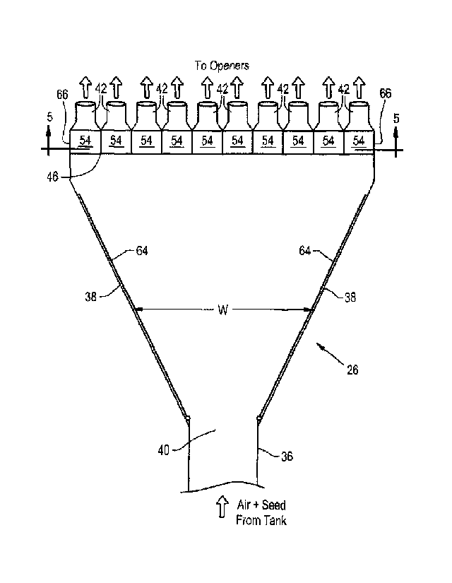
[0026] Referring now to Figs. 2-7, an embodiment of the main header 26
according to the
present invention is shown in greater detail. It should be appreciated that
even though the main
header 26 is shown in Figs. 2-7, the secondary header(s) 30 could be
structured in a similar
fashion. The header 26 includes a header body 36 with a pair of sidewalls 38,
an inlet 40 that
receives entrained material from the material tank 14 via material/air hose
22, and multiple
outlets 42 that connect to primary hoses 28 to distribute material to the
secondary headers 30. As
can be seen, the header body 36 has a width W defined between the sidewalls 38
that increases in
a direction from the inlet 40 toward the outlets 42, giving the header body 36
a fan-like shape.
The inlet 40 can be a circular shaped opening formed at a proximal end 44,
relative to the
material tank 14, of the header body 36 and the outlets 42 can have a circular
shape and be
aligned along a distal end 46 of the header body 36. The header body 36 can
have more than one
inlet, if desired. As can be seen, the header body 36 can have a circular
cross-sectional shape
adjacent to the proximal end 44 that gradually becomes a rectangular cross-
sectional shape at the
distal end 46, giving a flattened top surface 48 and bottom surface 50.
[0027] As shown in Figs. 2-7, each outlet 42 has an associated valve 52 that
is configured to
switch between a distributing position and a purging position, which will be
described further
below. As used herein, "associated with" refers to a valve 52 being placed and
configured in a
way that allows the valve 52 to block the flow of material or purging air into
its associated outlet
42. As shown, the valves 52 each include a gate 54 that is connected to an
actuator 56, shown as
a rod, with the gates 54 being hinged about valve openings 58 formed through
the top surface 48
of the header body 36. Each gate 54 can be sized and shaped to completely
cover the valve
openings 58, so that material and air do not freely flow through the valve
openings 58 when
covered by the gate 54. The actuators 56 can be controlled to selectively
switch the valves 52
between the distributing position and purging position by pushing or pulling
the gates 54 into the
7
CNHO 1 92.PROV
CA 02911130 2015-11-04
desired position.
100281 The header 26 further includes a plenum 60 that is selectively in fluid
communication
with the outlets 42. As can be seen, the plenum 60 has a body attached to the
top surface 48 of
the header body 36 that encloses a volume, which can be filled with purging
air from the blower
assembly 25 or a different air source. The plenum 60 can have air inlets 62
formed through that
connect to air hoses 24 to supply purging air to the plenum 60 from the blower
assembly 25.
Optionally, a valve (not shown) can be placed within one or both air inlets 62
to selectively
control when purging air is supplied to the plenum 60 from the blower assembly
25. The size
and shape of the plenum 60 can be chosen to provide varying purging air flow
patterns and
pressures out of the plenum 60. It should be appreciated that while the plenum
60 is shown
attached to the top surface 48 of the header body 36, the plenum 60 can be
placed at any location
that allows for the plenum 60 to be in selective fluid communication with the
outlets 42.
100291 As can be seen in Fig. 3, purging air within the plenum 60 is kept
isolated from an
outlet 42 when the outlet's 42 associated valve's 52 gate 54 completely covers
its respective
valve opening 58. In this position, which is referred to as the distributing
position, the valve 52
allows entrained material supplied to the header body 36 from the material/air
hose 22 to be
directed into the valve's 52 associated outlet 42 and be distributed to a
secondary header 30
through a primary hose 28. Each valve 52 also has a purging position,
illustrated by valve 52A
in Fig. 3, that allows purging air flow from the plenum 60 to be directed into
the valve's 52A
associated outlet 42 by gate 54A, which simultaneously blocks entrained
material from being
directed into the associated outlet 42. When the valve 52A is in the purging
position, the plenum
60 is in fluid communication with the valve's 52A associated outlet 42 and a
purging air flow
can be directed into the outlet 42 to clear material that is held within the
primary hose 28
connected to the outlet 42. Such a configuration allows for the distribution
of material from the
8
CNH0192.PROV
CA 02911130 2015-11-04
header 26 to be selectively controlled by controlling the actuators 56 to
adjust which valves 52
are in the distributing position and which valve(s) 52A are in the purging
position. As one or
more of the valves 52 is placed in the purging position, the metering unit 20
can be concurrently
adjusted so that the material flow rate through the outlets 42 with valves 52
in the distributing
position remains constant. It should also be appreciated that the purging air
supply to the plenum
60 from the blower system 25 can be selectively shut-off when material has
been purged from a
primary hose 28 in fluid communication with the plenum 60.
100301 Referring now to Figs. 4-7, the header 26 shown in Figs. 2-3 is shown
with a pair of
adjustable vanes 64 held within the header body 36. As can be seen in Figs. 4-
5, the vanes 64
are held against the sidewalls 38 so that the flow width of entrained material
through the header
body 36 is essentially the same as the width W of the header body 36. When the
vanes 64 are in
this position, entrained material is allowed to fan out as it flows through
the header body 36 and
evenly distribute to the outlets 42 at the distal end 46 of the header body
36. Such a position of
the vanes 64 can correspond to all of the outlets 42 having an associated
valve 52 in the
distributing position, so that any material directed toward an outlet 42 will
be directed into a
primary hose 28 toward a secondary header 30. When some of the outlets 42 have
associated
valves 52A in the purging position so that gates 54A are blocking entrained
material flow from
the material/air hose 22 into the outlets 42, as shown in Figs. 6-7, the vanes
64 can be adjusted so
that a flow width of entrained material through the header body 36 is
constrained to a flow width
V defined between the vanes 64. The flow width V of the vanes 64 can be
selectively controlled
to correspond to which outlets 42 have associated valves 52 in the
distributing position, so that
entrained material is mostly directed toward outlets 42 that are open. In this
sense, each vane 64
can be positioned so that it is aligned with an outer side 66 of one or more
open outlets to limit
the amount of entrained material that is directed toward a closed outlet. In
such a configuration,
9
CNH0192.PROV
CA 02911130 2015-11-04
the valves 52 can be switched from the distributing position to the purging
position sequentially
along the width W in a direction from the sidewalls 38 toward a center C of
the distal end 46 so
that the flow width V is directed at open outlets. It should be appreciated
that while two vanes 64
are shown, the flow width V could be adjusted by a single vane 64 as well, in
which case the
flow width V would be the distance between the single vane 64 and one of the
sidewalls 38. It is
contemplated that when one or more vanes 64 is included in the header 26, the
plenum 60 could
be an optional feature to purge the primary hoses 28 connected to the outlets
42. If the header 26
does not include a plenum, the positioning of the valves 52 that is referred
to as "a purging
position" can be referred to as "a blocking position," since the valves 52
block entrained material
from being directed into the outlets 42 without directing purging air flow
into the outlets 42.
LOON While this invention has been described with respect to at least one
embodiment, the
present invention can be further modified within the spirit and scope of this
disclosure. This
application is therefore intended to cover any variations, uses, or
adaptations of the invention
using its general principles. Further, this application is intended to cover
such departures from
the present disclosure as come within known or customary practice in the art
to which this
invention pertains and which fall within the limits of the appended claims.
CNH0192.PROV