Note : Les descriptions sont présentées dans la langue officielle dans laquelle elles ont été soumises.
CA 02911923 2015-11-06
WO 2015/016937 PCT/US2013/053375
1
DOWNHOLE POWER DELIVERY TOOL POWERED BY HYDROSTATIC
PRESSURE
Technical Field
[0001] The present disclosure relates generally to devices for use in a
wellbore in a subterranean formation and, more particularly (although not
necessarily exclusively), to downhole power delivery tools using hydrostatic
pressure within the wellbore.
Background
[0002] Various devices can be utilized in a well traversing a hydrocarbon-
bearing subterranean formation. Many such devices are configured to be
actuated, installed, or removed by a force applied to the device while
disposed in
the well. In one example, a packer device may be installed in production
tubing
in the well by applying a force to an elastomeric element of the packer. The
elastomeric element may expand in response to the force. Expansion of the
elastomeric element may restrict the flow of fluid through an annulus between
the
packer and the tubing. In another example, a force may be applied to a
removable plug device to withdraw the plug from an installed position in the
wellbore.
[0003] As the depth of a well increases, corresponding increased
temperatures may hinder the operation of various devices due to temperature
limitations of components of the devices. At some depths, a device may
experience greater pressure exerted upon the device by fluids in the wellbore.
Actuating such a device may require applying sufficient amounts of force to
CA 02911923 2015-11-06
WO 2015/016937 PCT/US2013/053375
2
overcome the force exerted by wellbore fluids to actuate, install, or remove
the
device.
Brief Description of the Drawings
[0004] FIG. 1 is a schematic illustration of a well system having a
downhole
power delivery tool using hydrostatic pressure according to one aspect of the
present disclosure.
[0005] FIG. 2 is a perspective view of a downhole power delivery tool
using
hydrostatic pressure according to one aspect of the present disclosure.
[0006] FIG. 3 is a lateral view of a downhole power delivery tool using
hydrostatic pressure according to one aspect of the present disclosure.
[0007] FIG. 4 is a longitudinal cross-sectional view of an exemplary
downhole power delivery tool using hydrostatic pressure according to one
aspect
of the present disclosure.
[0008] FIG. 5A is a longitudinal cross-sectional view of a first portion
of the
exemplary downhole power delivery tool using hydrostatic pressure according to
one aspect of the present disclosure.
[0009] FIG. 5B is a longitudinal cross-sectional view of a second portion
of
the exemplary downhole power delivery tool using hydrostatic pressure
according
to one aspect of the present disclosure.
[0010] FIG. 6 is a longitudinal cross-sectional view of the exemplary
downhole power delivery tool with a timer mechanism metered by a metering
mechanism according to one aspect of the present disclosure.
CA 02911923 2015-11-06
WO 2015/016937 PCT/US2013/053375
3
[0011] FIG. 7A is a longitudinal cross-sectional view of a first portion
of the
exemplary downhole power delivery tool with the timer mechanism metered by
the metering mechanism according to one aspect of the present disclosure.
[0012] FIG. 7B is a longitudinal cross-sectional view of a second portion
of
the exemplary downhole power delivery tool with the timer mechanism metered
by the metering mechanism according to one aspect of the present disclosure.
[0013] FIG. 8 is a lateral cross-sectional view of the exemplary downhole
power delivery tool using hydrostatic pressure according to one aspect of the
present disclosure.
[0014] FIG. 9 is a longitudinal cross-sectional view of the exemplary
downhole power delivery tool actuated by hydrostatic pressure according to one
aspect of the present disclosure.
[0015] FIG. 10A is a longitudinal cross-sectional view of a first portion
of the
exemplary downhole power delivery tool actuated by hydrostatic pressure
according to one aspect of the present disclosure.
[0016] FIG. 10B is a longitudinal cross-sectional view of a second
portion of
the exemplary downhole power delivery tool actuated by hydrostatic pressure
according to one aspect of the present disclosure.
[0017] FIG. 11 is a table describing exemplary levels of force produced
by
the exemplary downhole power delivery tool according to one aspect of the
present disclosure.
[0018] FIG. 12 is a longitudinal cross-sectional view of an alternative
exemplary downhole power delivery tool using hydrostatic pressure according to
one aspect of the present disclosure.
CA 02911923 2015-11-06
WO 2015/016937 PCT/US2013/053375
4
[0019] FIG. 13A is a longitudinal cross-sectional view of a first portion
of the
alternative exemplary downhole power delivery tool using hydrostatic pressure
according to one aspect of the present disclosure.
[0020] FIG. 13B is a longitudinal cross-sectional view of a second
portion of
the alternative exemplary downhole power delivery tool using hydrostatic
pressure according to one aspect of the present disclosure.
[0021] FIG. 14 is a lateral cross-sectional view of the alternative
exemplary
downhole power delivery tool using hydrostatic pressure according to one
aspect
of the present disclosure.
[0022] FIG. 15 is an additional lateral cross-sectional view of the
alternative
exemplary downhole power delivery tool using hydrostatic pressure according to
one aspect of the present disclosure.
[0023] FIG. 16 is a longitudinal cross-sectional view of the alternative
exemplary downhole power delivery tool actuated using hydrostatic pressure
according to one aspect of the present disclosure.
[0024] FIG. 17A is a longitudinal cross-sectional view of a first portion
of the
alternative exemplary downhole power delivery tool actuated using hydrostatic
pressure according to one aspect of the present disclosure.
[0025] FIG. 17B is a longitudinal cross-sectional view of a second
portion of
the alternative exemplary downhole power delivery tool actuated using
hydrostatic pressure according to one aspect of the present disclosure.
CA 02911923 2015-11-06
WO 2015/016937 PCT/US2013/053375
Detailed Description
[0026] Certain aspects and examples of the disclosure herein are directed
to downhole power delivery tools using hydrostatic pressure within the
wellbore.
The downhole power delivery tool can utilize hydrostatic pressure in the
wellbore
to apply force to a piston or otherwise actuate tools in the wellbore. For
example,
a downhole power delivery tool using hydrostatic pressure can include a port
adjacent to a movable barrier, such as a rupture disk. Hydrostatic pressure
can
be used to rupture the rupture disk or otherwise remove the barrier from the
port.
Removing the barrier from the port can allow fluid at a hydrostatic pressure
to be
communicated via the port from the wellbore to a piston disposed inside of the
downhole power delivery tool. The fluid at the hydrostatic pressure can apply
force to the piston. The piston can move in response to the application of the
force from the hydrostatic pressure. Movement of the piston can cause an
additional force to be applied to other components coupled to the piston, such
as
a rod used to actuate other downhole tools.
[0027] In some aspects, the downhole power delivery tool powered by
hydrostatic pressure can include a body that can be disposed in the fluid-
producing formation. The tool can also include at least a chamber, an inlet,
an
actuation mechanism, and a piston. The chamber can be disposed within the
body. The inlet can provide a path for communication of fluid into the chamber
from an annulus between the fluid-producing formation and the body. The
actuation mechanism can block fluid communication through the inlet. The fluid
communicated from the annulus can have a hydrostratic pressure associated
with the depth at which the downhole power delivery tool is disposed within
the
CA 02911923 2015-11-06
WO 2015/016937 PCT/US2013/053375
6
fluid-producing formation. Applying an actuation force to the actuation
mechanism can cause the actuation mechanism to unblock the inlet. Unblocking
the inlet can allow fluid to flow through the inlet. The fluid flow through
the inlet
can communicate the hydrostatic pressure from the annulus to the chamber. The
piston can be disposed adjacent to the chamber such that the hydrostatic
pressure communicated to the chamber causes a a first force to be applied to
the
piston. In response to the first force being applied to the piston, the piston
can
apply a second force to a rod that moves the rod relative to the body.
Harnessing
the hydrostatic pressure to power the movement of the rod allows the rod to
provide levels of force that correspond to the high pressures exerted upon
devices during operation in deep, high pressure, high temperature wells.
[0028] The actuation mechanism can be implemented using any suitable
mechanism. In some aspects, the actuation mechanism can be a rupture disk.
The rupture disk can have a burst pressure corresponding to an actuation force
of the downhole power delivery tool. The burst pressure can be a pressure
applied to the rupture disk that is sufficient to cause the rupture disk to
rupture.
The rupture disk can rupture in response to the actuation force being applied
to
the rupture disk. Rupturing the rupture disk can unblock the inlet. Unblocking
the
inlet can allow fluid to flow through the inlet into the chamber.
[0029] In additional or alternative aspects, the actuation mechanism can
be
a piston or other barrier positioned to block or obstruct the fluid path
through the
inlet. A suitable actuation force can be applied to the piston or other
barrier.
Applying the actuation force to the piston or other barrier can move the
piston or
barrier such that fluid can flow through the inlet.
CA 02911923 2015-11-06
WO 2015/016937 PCT/US2013/053375
7
[0030] In additional or alternative aspects, the actuation mechanism can
be
a piston or other member having a structure that defines a flow path into the
chamber. The piston or other member can be positioned such that the defined
flow path is not aligned with the inlet, thereby preventing fluid
communication
from the inlet to the chamber. A suitable actuation force can be applied to
the
actuation mechanism. Applying the actuation force to the actuation mechanism
can move the piston or other member such that the flow path and the inlet are
aligned. Aligning the flow path and the inlet can allow fluid communication
through the inlet and the flow path into the chamber.
[0031] The actuation force for the actuation mechanism can be provided by
any suitable mechanism and/or process. In some aspects, the actuation force
can be generated by the hydrostatic pressure. The actuation mechanism can be
triggered automatically upon reaching a target depth at which the hydrostatic
pressure is sufficient to provide the actuation force. In a non-limiting
example,
the actuation mechanism may include a rupture disk. The rupture disk can
rupture in response to a pressure corresponding to the hydrostatic pressure at
a
target depth. In another non-limiting example, the actuation mechanism may be
a piston having dimensions and/or friction surfaces such that the hydrostatic
pressure at the target depth is sufficient to cause the piston to move out of
the
way or into alignment at a target depth.
[0032] In other aspects, the actuation force can be generated by impact
from a solid object. For example, the actuation mechanism may include a
jarring
apparatus. In one non-limiting example, the jarring apparatus can contact a
member with sufficient force to allow fluid flow into the chamber by either
CA 02911923 2015-11-06
WO 2015/016937 PCT/US2013/053375
8
repositioning the member to remove an inlet barrier or realigning the member
to
provide a flow path. In another non-limiting example, the jarring apparatus
can
contact a rupture disk with sufficient force to cause rupture.
[0033] In
other aspects, the actuation mechanism can include a chemical
charge configured to provide the actuation force. For example, detonation of a
chemical charge may directly rupture a rupture disk or cause a projectile to
rupture the rupture disk. In another non-limiting example, detonation of a
chemical charge may reposition a piston or other member to remove an inlet
barrier or realign the piston or other member to provide a flow path. The
chemical charge may be detonated by any suitable mechanism such as, but not
limited to, a timer providing an electrical signal to the chemical charge or a
remote signal source communicating an electric signal to the chemical charge.
[0034] In
additional or alternative aspects, the tool can include a hydraulic
fluid used to apply the force to the rod of the downhole power delivery tool.
In
some aspects, the tool can further include a metering mechanism positioned
adjacent to the hydraulic fluid and proximate to the rod. The
metering
mechanism can restrict a flow of the hydraulic fluid such that the rate of the
hydraulic fluid flow to the rod is regulated. The rod can be moved at a
controlled
rate according to the rate of flow of the hydraulic fluid through the metering
mechanism. In some aspects, use of a hydraulic fluid with known properties can
be used for metering or other functions for deployment environments in which
the
composition of wellbore fluids may be difficult to determine or may be
unsuitable
for functions such as metering.
CA 02911923 2015-11-06
WO 2015/016937 PCT/US2013/053375
9
[0035] In additional or alternative aspects, the tool can include a
hydraulic
timer assembly for providing a delay between the tool receiving the actuation
force and the movement of the rod. The hydraulic timer assembly can include a
timer piston that can move from a first position to a second position in
response
to a force. The hydraulic timer assembly can also include a hydraulic fluid
that
opposes the movement of the piston from the first position to the second
position.
The hydraulic fluid can be displaced in response to the movement of the timer
piston from the first position to the second position. The hydraulic timer
assembly
can further include a metering mechanism. The metering mechanism can restrict
a flow of the hydraulic fluid such that the rate of the hydraulic fluid flow
is
regulated as the hydraulic fluid is displaced in response to the movement of
the
timer piston. The regulation of the hydraulic fluid flow can regulate the rate
at
which the hydraulic fluid is displaced and the rate at which the timer piston
moves
from the first position to the second position. The hydraulic timer assembly
can
provide a length of delay corresponding to a duration of the movement of the
timer piston between the first and second positions.
[0036] These illustrative examples are given to introduce the reader to
the
general subject matter discussed here and are not intended to limit the scope
of
the disclosed concepts. The following sections describe various additional
aspects and examples with reference to the drawings in which like numerals
indicate like elements, and directional descriptions are used to describe the
illustrative aspects. The following sections use directional descriptions such
as
"above," "below," "upper," "lower," "upward," "downward," "left," "right,"
"uphole,"
"downhole," etc. in relation to the illustrative aspects as they are depicted
in the
CA 02911923 2015-11-06
WO 2015/016937 PCT/US2013/053375
figures, the upward direction being toward the top of the corresponding figure
and
the downward direction being toward the bottom of the corresponding figure,
the
uphole direction being toward the surface of the well and the downhole
direction
being toward the toe of the well. Like the illustrative aspects, the numerals
and
directional descriptions included in the following sections should not be used
to
limit the present disclosure.
[0037] FIG. 1 schematically depicts a well system 100 having a tubing
string 112 with at least one downhole power delivery tool 116 using
hydrostatic
pressure. The well system 100 includes a bore that is a wellbore 102 extending
through various earth strata. The wellbore 102 has a substantially vertical
section 104 and a substantially horizontal section 106. The substantially
vertical
section 104 and the substantially horizontal section 106 may include a casing
string 108 cemented at an upper portion of the substantially vertical section
104.
The substantially horizontal section 106 extends through a hydrocarbon bearing
subterranean formation 110.
[0038] The tubing string 112 within wellbore 102 extends from the surface
to the subterranean formation 110. The tubing string 112 can provide a conduit
for formation fluids, such as production fluids produced from the subterranean
formation 110, to travel from the substantially horizontal section 106 to the
surface. Pressure from a bore in a subterranean formation can cause formation
fluids, including production fluids such as gas or petroleum, to flow to the
surface.
[0039] The well system 100 can also include at least one downhole power
delivery tool 116. The downhole power delivery tool 116 can be deployed in the
tubing string 112. The downhole power delivery tool 116 can apply force to one
CA 02911923 2015-11-06
WO 2015/016937 PCT/US2013/053375
11
or more downhole components, as described in detail with respect to FIGS. 2-
17B below.
[0040] Although FIG. 1 depicts the downhole power delivery tool 116 in
the
substantially horizontal section 106, the downhole power delivery tool 116 can
be
located, additionally or alternatively, in the substantially vertical section
104. In
some aspects, the downhole power delivery tool 116 can be disposed in simpler
wellbores, such as wellbores having only a substantially vertical section. A
downhole power delivery tool 116 can be disposed in openhole environments,
such as is depicted in FIG. 1, or in cased wells. Although FIG. 1 depicts a
single
downhole power delivery tool 116 deployed in the tubing string 112, any number
of downhole power delivery tool can be deployed in the tubing string 112.
[0041] FIG. 2 is a perspective view of an exemplary downhole power
delivery tool 116 according to one aspect. FIG. 3 is a lateral view of the
downhole power delivery tool 116. The downhole power delivery tool 116 can
include a body 202 and a rod 204.
[0042] The body 202 can have a size sufficient for the downhole power
delivery tool 116 to be inserted and removed from the tubing string 112. The
body 202 can define an inner volume in which additional components of the
downhole power delivery tool 116 can be disposed. A wall of the body 202 can
have a thickness sufficient to withstand heat and/or pressure of a target
depth in
the well system 100 at which the downhole power delivery tool 116 is to be
deployed. The body 202 can be manufactured from any suitable material, such
as steel or other metals.
CA 02911923 2015-11-06
WO 2015/016937 PCT/US2013/053375
12
[0043] The rod 204 can be extended from and/or retracted into the body
202. Extending or retracting the rod 204 can apply a force to another tool
within
the tubing string 112. The rod 204 can include any suitable coupling mechanism
206 for attaching or otherwise coupling the downhole power delivery tool 116
with
another tool within the tubing string 112. In one non-limiting example, the
coupling mechanism 206 may be a threaded surface that can interface with a
mating threaded surface on another tool within the tubing string 112. In
another
non-limiting example, the coupling mechanism 206 may include a flange that can
fit within a groove in a second tool within the tubing string 112. The flange
of the
coupling mechanism 206 and the groove in a second tool can maintain the rod
204 and the second tool in a locked position.
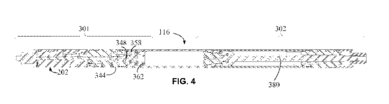
[0044] FIG. 4 is a longitudinal cross-sectional view depicting an
exemplary
downhole power delivery tool 116. The cross-sectional view is taken along the
line 4-4' depicted in FIG. 3. As depicted in FIG. 4, the downhole power
delivery
tool 116 can include a body 202, an actuation inlet 344, a barrier piston 348,
a
chamber 358, a piston 362, and a rod 380.
[0045] The actuation inlet 344 can be disposed through the body 202. The
actuation inlet 344 can communicate fluid into the chamber 358 from an annulus
between the body 202 and the formation 110. The annular fluid can have a
hydrostatic pressure.
[0046] The chamber 358 and the barrier piston 348 can be disposed within
the body 202. The barrier piston 348 can prevent communication of the annular
fluid via the actuation inlet 344. Applying an actuation force to the barrier
piston
348 can displace the barrier piston 348. Displacing the barrier piston 348 can
CA 02911923 2015-11-06
WO 2015/016937 PCT/US2013/053375
13
allow communication of the annular fluid into the chamber 358 via the
actuation
inlet 344. In one non-limiting example, a hydrostatically actuated electronic
timing circuit utilizing a short stroke pushing mechanism can be used to
displace
the barrier piston 348 and actuate the downhole power delivery tool 116. In
another non-limiting example, an electronic power delivery tool can be used to
move the barrier piston 348 to actuate the downhole power delivery tool 116.
[0047] The
piston can be disposed within the body 202 and proximate to
the chamber 358. Communication of the annular fluid into the chamber 358 can
cause annular fluid in the chamber 358 to apply a first force to the piston
362.
Applying a first force to the piston 362 can cause the piston 362 to apply a
second force to the rod 380. FIG. 4 depicts the rod 380 retracted into the
body
202 of the downhole power delivery tool 116. Applying the second force to the
rod 380 can extend the rod 380. Extending the rod 380 can apply a force to
another tool within the tubing string 112.
[0048]
FIG. 5A is a longitudinal cross-sectional view depicting a first portion
301 of the exemplary downhole power delivery tool 116. As depicted in FIG. 5A,
the body 202 of the downhole power delivery tool 116 can include a timer entry
inlet 312 and a rupture disk 314. The timer entry inlet 312 can be configured
as a
vacuum pressure chamber. In some aspects, a vacuum pressure chambers can
be an atmospheric pressure chambers filled with air. A vacuum pressure
chamber can be evacuated through the vacuum test ports 318 using a vacuum
pump. In some aspects, evacuating the chamber can provide a seal test.
[0049] The
rupture disk 314 can be disposed proximate to or within the
timer entry inlet 312. Positioning the rupture disk 314 proximate to or within
the
CA 02911923 2015-11-06
WO 2015/016937 PCT/US2013/053375
14
timer entry inlet 312 can seal the timer entry inlet 312. Sealing the timer
entry
inlet 312 can maintain a vacuum pressure within the timer entry inlet 312.
Sealing the timer entry inlet 312 can also prevent fluid communication via the
timer entry inlet 312 from the annulus between the body 202 and the formation
110 to an inner volume of the body 202.
[0050] The downhole power delivery tool can also include vacuum test
ports 318, 328, 354. The vacuum test port 318 can be positioned adjacent to
the
timer entry inlet 312. The vacuum test port 318 can provide an interface by
which
a diagnostic tool can determine whether the timer entry inlet 312 is
functioning
correctly and is maintaining a vacuum. The vacuum test port 318 can verify the
proper fit and function of the vacuum chamber seals. Vacuum test port 318 can
be utilized to verify that the vacuum pressure of the timer entry inlet 312
has not
been disturbed. The vacuum test port 328 can be used to verify that the
passageway 322 is at a vacuum pressure. The vacuum test port 354 can be
used to test the seal on a check valve 342.
[0051] The downhole power delivery tool can include a timer piston 320.
The timer piston 320 can be disposed in a passageway 324. The passageway
324 can define a path through which the timer piston 320 can move. The barrier
piston 348 can be positioned proximate to an end of passageway 324. The
barrier piston 348 can seal the actuation inlet 344. Sealing the actuation
inlet 344
can prevent fluid communication from the annulus between the body 202 and the
formation 110 through the actuation inlet 344. Preventing fluid communication
through the actuation inlet 344 can prevent fluid communication through a
conduit
356 into the chamber 358 in the body 202. The chamber 358 can also be
CA 02911923 2015-11-06
WO 2015/016937 PCT/US2013/053375
configured as a vacuum pressure chamber. A vacuum test port 352 can be
provided in the body 202 to determine whether the chamber 358 is maintaining a
vacuum pressure.
[0052] The downhole power delivery tool 116 can also include a quantity
of
hydraulic fluid 364. The hydraulic fluid can be used to communicate a force
from
the piston 362 to the rod 380. The piston 362 can be positioned in between the
chamber 358 and the hydraulic fluid 364.
[0053] FIG. 5B is a longitudinal cross-sectional view depicting a second
portion 302 of the exemplary downhole power delivery tool 116. As depicted in
FIG. 5B, the downhole power delivery tool 116 can also include a filter 366, a
fill
plug 368, a metering mechanism 370, and a rod chamber 376.
[0054] The fill plug 368 may be removed to introduce the hydraulic fluid
364
into the downhole power delivery tool 116. The fill plug 368 may be reinserted
to
seal the hydraulic fluid 364 within the downhole power delivery tool 116.
[0055] The filter 366 and/or the metering mechanism 370 can be disposed
at position such that the filter 366 and/or the metering mechanism 370 are in
fluid
communication with the hydraulic fluid 364. A piston head 374 can be
positioned
adjacent to the hydraulic fluid 364 so as to prevent fluid communication of
the
hydraulic fluid 364 into the rod chamber 376. The piston head 374 can be
connected to the rod 380. The rod 380 can be positioned in the rod chamber
376. The rod 380 can extend from the body 202. In some aspects, the rod 380
can include an adaptor end 382. The adaptor end 382 can provide an interlace
for coupling the downhole power delivery tool 116 with other downhole tools.
CA 02911923 2015-11-06
WO 2015/016937 PCT/US2013/053375
16
[0056] The downhole power delivery tool 116 can also include a protective
sheath 386. In some aspects, the protective sheath 386 may be coupled to the
body of the downhole power delivery tool 116. In other aspects, the sheath may
be coupled to the rod 380. The protective sheath 386 can be coupled to a
suitable part of the downhole power delivery tool 116 via any suitable
mechanism. A non-limiting example of a suitable mechanism for coupling the
protective sheath 386 to the downhole power delivery tool 116 is a fastener
384.
Coupling the protective sheath 386 to the downhole power delivery tool 116 can
protect the adaptor end 382 during transport or storage of the downhole power
delivery tool 116. The protective sheath 386 can be removed to prepare the
downhole power delivery tool 116 for deployment and actuation.
[0057] Actuation of the downhole power delivery tool 116 can be initiated
by rupturing the rupture disk 314. The rupture disk 314 can rupture in
response
to a pressure differential across the rupture disk 314 exceeding the pressure
rating of the rupture disk 314. In some aspects, the rupture disk 314 can
rupture
at a target hydrostatic pressure corresponding to a target depth. The timer
entry
inlet 312 can be set to a vacuum pressure. Setting the timer entry inlet 312
to the
vacuum pressure can cause the pressure differential across the rupture disk to
be approximately equal to the hydrostatic pressure of the fluid from the
annulus
between the body 202 and the formation 110. In other aspects, an explosive
charge 308 can be positioned adjacent to the rupture disk 314. Detonating the
charge 308 can cause the rupture disk 314 to rupture. In one non-limiting
example, the detonation of the charge 308 can rupture the rupture disk 314. In
another non-limiting example, the detonation of the charge 308 can propel an
CA 02911923 2015-11-06
WO 2015/016937 PCT/US2013/053375
17
object toward the rupture disk 314 with sufficient force to rupture the
rupture disk
314.
[0058] Rupturing the rupture disk 314 can allow liquid, gas, or some
combination thereof from the annulus to flow into the timer entry inlet 312.
An 0-
ring 326a can be disposed between the outer diameter of the timer piston 320
and the passageway 324. The 0-ring 326a can prevent a flow of the fluid past
the timer piston 320 through the passageway 324. Fluid at a hydrostatic
pressure that enters the timer entry inlet 312 from outside the body 202 can
communicate the hydrostatic pressure to an upper face 316 of the timer piston
320. Communicating the hydrostatic pressure to the upper face 316 of the timer
piston 320 can produce a force on the upper face 316 of the timer piston 320.
Producing a force on the upper face 316 of the timer piston 320 can cause the
timer piston 320 to move through the passageway 324 toward the barrier piston
348.
[0059] Movement of the timer piston 320 can be resisted by a quantity of
timer hydraulic fluid 334. The timer hydraulic fluid 334 can be disposed
around a
lower portion of the timer piston 320 in a timer fluid chamber 340. The lower
portion of timer piston 320 can be adjacent to an upper portion 330 of the
timer
piston 320 having a greater diameter than the lower portion. The upper portion
330 of the timer piston 320 can include an 0-ring 326b positioned between the
circumference of the timer piston 320 and the passageway 324. The 0-ring 326b
can prevent the timer hydraulic fluid 334 from flowing past the upper portion
330
of the timer piston 320. The timer piston 320 can also include an 0-ring 326c
positioned on an end of the timer piston 320 distal to the upper portion 330
of the
CA 02911923 2015-11-06
WO 2015/016937 PCT/US2013/053375
18
timer piston 320. The 0-ring 326c can prevent timer hydraulic fluid 334 from
flowing into a passageway 346 adjacent the timer fluid chamber 340. Preventing
timer hydraulic fluid 334 from flowing past the upper portion 330 of the timer
piston 320 or into the passageway 346 can prevent leakage of the timer
hydraulic
fluid 334. Preventing leakage of the timer hydraulic fluid 334 can maintain
the
timer hydraulic fluid 334 in the timer fluid chamber 340 such that a movement
of
the timer piston 320 in the passageway 324 toward the barrier piston 348 can
exert a force on the timer hydraulic fluid 334.
[0060] The force exerted on the timer hydraulic fluid 334 by the timer
piston
320 can be sufficient to displace the timer hydraulic fluid 334 from the timer
fluid
chamber 340. The timer hydraulic fluid 334 can be displaced from the timer
fluid
chamber 340 and communicated through a passageway 332 to a position
adjacent to the upper portion 330 of timer piston 320. Communicating the timer
hydraulic fluid 334 from a first position on a first side of the upper portion
330 of
the timer piston 320 to a second position on a second side of the upper
portion
330 of the timer piston 320 can cause the timer hydraulic fluid 334 to apply a
balanced level of hydraulic pressure to both sides of the upper portion 330.
Balancing the hydraulic pressure on the upper portion 330 of the timer piston
320
can allow the hydrostatic pressure applied to the upper face 316 of the timer
piston 320 to move the timer piston 320 with less interference from the
displacement of the timer hydraulic fluid 334.
[0061] Communicating the timer hydraulic fluid 334 through the
passageway 332 can cause the timer hydraulic fluid 334 to pass through a
filter
338. Communicating the timer hydraulic fluid 334 through the passageway 332
CA 02911923 2015-11-06
WO 2015/016937 PCT/US2013/053375
19
can also cause the timer hydraulic fluid 334 to pass through a timer metering
mechanism 336.
[0062] The timer metering mechanism 336 can regulate the speed of the
movement of the timer piston 320. The timer metering mechanism 336 can
restrict a flow of the timer hydraulic fluid 334 passing through the metering
mechanism. Restricting the flow of the timer hydraulic fluid 334 can reduce a
rate
of flow of the timer hydraulic fluid 334. The reduced flow rate can reduce a
rate
at which the timer hydraulic fluid 334 is displaced from the timer fluid
chamber
340. Reducing the rate at which the timer hydraulic fluid 334 is displaced can
cause the timer piston 320 to move at a reduced speed.
[0063] FIG. 6 is a longitudinal cross-sectional view of the exemplary
downhole power delivery tool 116 with a timer piston 320 metered by a timer
metering mechanism 336. The timer metering mechanism 336 can cause the
timer piston 320 to move at a metered rate into contact with the barrier
piston
348, as depicted by the rightward arrow in FIG. 6. The movement of the timer
piston 320 in contact with the barrier piston 348 can exert a force on the
barrier
piston 348. The force exerted on the barrier piston 348 can cause the barrier
piston 348 to move.
[0064] FIG. 7A is a longitudinal cross-sectional view of the first
portion 301
of the exemplary downhole power delivery tool 116 with the timer piston 320
metered by the timer metering mechanism 336. As depicted in FIG. 7A, the timer
piston 320 can move the barrier piston 348. Moving the barrier piston 348 can
expose the actuation inlet 344. Exposing the actuation inlet 344 can allow
fluid at
a hydrostatic pressure from outside of the body 202 to be communicated through
CA 02911923 2015-11-06
WO 2015/016937 PCT/US2013/053375
the actuation inlet 344 to the chamber 358. Communicating the fluid to the
chamber 358 can increase the pressure in the chamber 358 from a vacuum
pressure to the hydrostatic pressure.
[0065] Fluid may be communicated from the actuation inlet 344 to the
chamber 358 by any suitable path. For example, FIG. 7A depicts a fluid flow
path
in which the fluid flows into the chamber 358. The fluid can flow through the
actuation inlet 344 toward the barrier piston 348. The fluid can traverse the
barrier piston 348 by flowing around a smaller diameter portion of the barrier
piston 348 and/or by flowing through a conduit provided in an end 350 of the
barrier piston 348. Fluid traversing the barrier piston 348 can flow through a
conduit 356. Fluid can flow through the conduit 356 and into the chamber 358.
[0066] FIG. 7B is a longitudinal cross-sectional view of a second portion
302 of the exemplary downhole power delivery tool 116 with the timer mechanism
metered by the metering mechanism. As discussed above with respect to FIG.
5B, the power downhole power delivery tool 116 can include hydraulic fluid
364, a
metering mechanism 370, a piston head 374, a rod chamber 376, and a rod 380.
The piston head 374 can be disposed adjacent to the hydraulic fluid 364.
Positioning the piston head 374 adjacent to the hydraulic fluid 364 can
prevent
fluid communication of the hydraulic fluid 364 into the rod chamber 376. The
position of the piston head 374 adjacent to the hydraulic fluid 364 can allow
the
pressure of the hydraulic fluid 364 to exert a force on the piston head 374.
The
force exerted on the piston head 374 by the hydraulic fluid 364 can cause the
piston head 374 to move and extend the rod 380.
CA 02911923 2015-11-06
WO 2015/016937 PCT/US2013/053375
21
[0067] As depicted in FIG. 7B, the downhole power delivery tool 116 can
also include shear pins 372. The shear pins 372 may be fabricated with a
suitable size and material so as to be capable of withstanding forces up to a
specific force threshold. The shear pins 372 can prevent inadvertent movement
of the piston head 374 by restraining the piston head 374 in place in the
absence
of the specific level of force. Applying a force having a sufficient magnitude
to the
shear pins 372 can break the shear pins 372. Breaking the shear pins 372 can
remove a restraint on the piston head 374. As depicted in FIG. 7B, the shear
pins 372 can resist the force that the timer hydraulic fluid 334 exerts on the
piston
head 374. Resisting the force exerted by the timer hydraulic fluid 334 can
maintain the position of the rod 380. Increasing the pressure of the timer
hydraulic fluid 334 to a sufficient magnitude can cause the timer hydraulic
fluid
334 to exert a force on the piston head 374 that is sufficient to break the
shear
pins 372. Breakage of the shear pins 372 can allow the piston head 374 to move
in response to the force exerted by the timer hydraulic fluid 334.
[0068] The rod chamber 376 can also be configured as a vacuum pressure
chamber. Configuring the rod chamber 376 as a vacuum pressure chamber can
reduce resistance to the movement of the piston head 374 during extension of
the rod 380 from the body 202.
[0069] FIG. 8 is a lateral cross-sectional view of the exemplary downhole
power delivery tool 116 using hydrostatic pressure. FIG. 8 is taken along the
line
8-8' depicted in FIG. 7B of the exemplary downhole power delivery tool 116. As
depicted in FIG. 8, a power delivery downhole power delivery tool 116 can
include a vacuum test port 805. The vacuum test port 805 can be in fluid
CA 02911923 2015-11-06
WO 2015/016937 PCT/US2013/053375
22
communication with the rod chamber 376 via a test channel 378 depicted in FIG.
7B. The vacuum test port 805 can be utilized to test the rod chamber 376 for
deployment. Testing the rod chamber 376 can include verifying that the rod
chamber 376 is maintaining a vacuum pressure.
[0070] FIG. 9 is a longitudinal cross-sectional view of the exemplary
downhole power delivery tool 116 actuated by hydrostatic pressure. As depicted
by the rightward arrow in FIG. 9, communication of fluid having a hydrostatic
pressure via the actuation inlet 344 can cause the chamber 358 to fill with
the
annular fluid. Filling the chamber 358 can cause the piston 362 to move.
Movement of the piston 362 can cause rod 380 to extend.
[0071] FIG. 10A is a longitudinal cross-sectional view of a first portion
of the
exemplary downhole power delivery tool 116 actuated by hydrostatic pressure.
As depicted in FIG. 10A, the chamber 358 can be filled with fluid from outside
the
body 202. Filling the chamber 358 with the fluid can cause the chamber to
approach the hydrostatic pressure of the fluid. Pressurizing the chamber 358
to
approach hydrostatic pressure can cause the chamber 358 to exert a sufficient
force on the piston 362 to cause the piston 362 to move away from a position
proximate to the barrier piston 348.
[0072] FIG. 10B is a longitudinal cross-sectional view of a second
portion of
the exemplary downhole power delivery tool 116 actuated by hydrostatic
pressure. As depicted by the rightward arrow in FIG. 10B, the force exerted on
the piston 362 by the chamber 358 at hydrostatic pressure can cause the piston
to move toward a position proximate to the filter 366 and the metering
mechanism 370. The piston 362 can communicate the hydrostatic pressure from
CA 02911923 2015-11-06
WO 2015/016937 PCT/US2013/053375
23
the chamber 358 to the hydraulic fluid 364 disposed on the opposite side of
the
piston 362. Communicating the hydrostatic pressure to the hydraulic fluid 364
can cause the hydraulic fluid 364 to be pressurized to approximately the same
pressure as the hydrostatic pressure of the fluid in the chamber 358. The
movement of the piston 362 can cause the hydraulic fluid 364 to flow into the
rod
chamber 376. The flow of the hydraulic fluid 364 having a pressure at or near
the
hydrostatic pressure into the rod chamber 376 can exert a force on the piston
head 374 of the rod 380. The force exerted on the piston head 374 of the rod
can cause the rod 380 to extend from the downhole power delivery tool 116. The
extension of the rod 380 can actuate another downhole tool in the tubing
string
112.
[0073] As depicted in FIG. 10B, the metering mechanism 370 and/or the
filter 366 can be disposed between the piston 362 and the piston head 374 such
that the hydraulic fluid 364 may also flow through the filter 366 and/or the
metering mechanism 370. The metering mechanism 370 can cause the timer
hydraulic fluid 334 to enter the rod chamber 376 at controlled rate.
Controlling
the rate at which the timer hydraulic fluid 334 enters the rod chamber 376 can
control the rate at which the rod extends to deliver power to another tool.
[0074] FIG. 11 is a table showing exemplary levels of force produced by
the downhole power delivery tool 116. The amount of power that can be
delivered by a downhole power delivery tool 116 can vary according to various
features, including the hydrostatic pressure at a depth in the wellbore 102
and the
dimensions of different components of the downhole power delivery tool 116. As
non-limiting examples, FIG. 11 depicts possible power delivery in pounds-force
CA 02911923 2015-11-06
WO 2015/016937 PCT/US2013/053375
24
("LBF") of different sizes of the downhole power delivery tool 116 based on
the
hydrostatic pressure available.
[0075] Possible power delivery can be based on the forces exerted on the
piston head 374 and the rod 380. The hydraulic fluid 364 can exert a force on
the
piston head 374 that is directly opposed by a force exerted on the rod 380 by
the
annular fluid. The hydraulic fluid 364 and the annular fluid can each have a
pressure equivalent to the hydrostatic pressure such that the net force
exerted by
the downhole power delivery tool 116 is equivalent to the hydrostatic pressure
multiplied by the differential area between cross-sectional area of the piston
head
374 and the cross-sectional area of the rod 380.
[0076] For example, the first row of the table depicted in FIG. 11 refers
to
an exemplary downhole power delivery tool 116 having a body with a nominal
outer diameter of 3.8 inches. The diameter of the piston head 374 can be 2.998
inches such that a cross-sectional area of the piston head 374 is 7.059 square
inches. The diameter of the rod 380 can be 1.25 inches such that a cross-
sectional area of the rod 380 is 1.227 square inches. A hydrostatic pressure
of
12,000 pounds per square inch applied to the differential cross-sectional area
of
5.832 square inches can provide an power delivery force of 69,984 LBF.
[0077] In additional or alternative aspects, a downhole power tool may be
actuated via impact from a solid object. FIG. 12 is a longitudinal cross-
sectional
view of an alternative exemplary downhole power delivery tool 116' using
hydrostatic pressure. The cross-sectional view is taken along the line 4-4'
depicted in FIG. 3. As depicted in FIG. 12, the downhole power delivery tool
116'
can include a body 202', a structure 604, a piston 642, a hydraulic fluid 650,
and
CA 02911923 2015-11-06
WO 2015/016937 PCT/US2013/053375
a rod 680. Actuation of the structure 604 can cause the piston 642 to move.
Movement of the piston 642 can cause the hydraulic fluid 650 to be
communicated toward the rod 680. Communication of the hydraulic fluid 650
toward the rod 680 can cause the rod 680 to retract into the body 202' of the
downhole power delivery tool 116'. Retraction of the rod 680 can be utilized
to
deliver power to other tools disposed in the wellbore.
[0078] FIG. 13A is a longitudinal cross-sectional view of a first portion
801
of the alternative exemplary downhole power delivery tool 116' using
hydrostatic
pressure. As depicted in FIG. 13A, the downhole power delivery tool 116' can
include an inlet 608, a structure 604, a vacuum pressure chamber 622 and an
actuation structure 632.
[0079] The inlet 608 can be positioned in the body 202' so as to provide
fluid communication through the inlet 608 into the body 202' from the annulus
between the body 202' and the formation 110.
[0080] In a first position, at least a portion of the structure 604 can
protrude
from the body 202'. An actuation force can be applied to the protruding
portion of
the structure 604. For example, a solid object 602 can contact the structure
604
to apply the actuation force.
[0081] The structure 604 can define a port 606 and a conduit 624. In the
first position, the port 606 can be positioned such that the port 606 is not
aligned
with the inlet 608, thereby preventing fluid communication from outside of the
body 202' through the inlet 608 to an inner diameter of the body 202'.
[0082] The vacuum pressure chamber 622 can be positioned proximate to
the structure 604. The structure 604 can displace into the vacuum pressure
CA 02911923 2015-11-06
WO 2015/016937 PCT/US2013/053375
26
chamber 622 in response to the actuation force being applied to the structure
604. In some aspects, the downhole power delivery tool 116' can also include a
vacuum test port 618 to test a check valve 616 and a vacuum test port 628 to
check a passage 626.
[0083] In some aspects, the downhole power delivery tool 116' can also
include a balance inlet 612 through the body 202'. The balance inlet 612 can
provide a flow path for communicating fluid from the wellbore 102 to a surface
614 of the structure 604. The fluid can exert a pressure equal to the
hydrostatic
pressure of the wellbore on the surface 614, thereby counteracting the
hydrostatic pressure acting on the structure 604 from outside of the body
202'. A
balanced distribution of hydrostatic pressure can prevent the hydrostatic
force
outside the body 202' from causing inadvertent movement of the structure 604.
In some aspects, the structure 604 can be secured using shear pins 610 or
another suitable retention mechanism to prevent inadvertent movement of the
structure 604 in the absence of an actuation force.
[0084] The actuation structure 632 can be disposed proximate to the
structure 604. The actuation structure 632 can be positioned to block a
passage
626 into a chamber 634. The chamber 634 can be positioned adjacent to the
piston 642. The actuation structure can be positioned to block an actuation
inlet
630 disposed in the body 202'. The actuation structure 632 can include a
passage 638. The passage 638 can provide a flow path through the actuation
structure 632 into a piston chamber 646. The piston chamber can be positioned
within the piston 642.
CA 02911923 2015-11-06
WO 2015/016937 PCT/US2013/053375
27
[0085] FIG. 13B is a longitudinal cross-sectional view of a second
portion
802 of the alternative exemplary downhole power delivery tool 116' using
hydrostatic pressure. As depicted in FIG. 13B the downhole power delivery tool
116' can include a fill plug 654, a pressure chamber 670, a rupture disk 672,
a
filter 652, a metering mechanism 656, a rod conduit 660, and a rod reservoir
676.
[0086] The fill plug 654 may be removed to introduce the quantity of
hydraulic fluid 650 into a downhole power delivery tool 116'. The fill plug
654
may be replaced to seal the hydraulic fluid 650 within the tool. In some
aspects,
the fill plug 654 depicted in FIG. 13B can be omitted.
[0087] The rod reservoir 676 can be disposed within the rod 680. The rod
conduit 660 can provide a flow path for fluid communication of the hydraulic
fluid
650 into the rod reservoir 676. The filter 652 can be disposed in the flow
path of
the hydraulic fluid 650 such that the fluid is communicated through the filter
652.
A metering mechanism 656 can be disposed in the flow path of the hydraulic
fluid
650.
[0088] The pressure chamber 670 can be positioned proximate to the rod
680. The rupture disk 672 can be positioned adjacent to the rod reservoir 676.
The rupture disk 672 can be positioned so as to prevent communication of the
hydraulic fluid 650 between the rod reservoir 676 and the pressure chamber
670.
[0089] The rod chamber 662 can be configured as a vacuum chamber.
FIG. 14 is a lateral cross-sectional view of the alternative exemplary
downhole
power delivery tool 116' using hydrostatic pressure. The view in FIG. 14 is
taken
along the line 14-14' depicted in FIG. 13B. As depicted in FIG. 14, the
downhole
power delivery tool 116' may include a vacuum test port 905. The vacuum test
CA 02911923 2015-11-06
WO 2015/016937 PCT/US2013/053375
28
port 905 can be utilized to test the rod chamber 662 prior to deploying the
downhole power delivery tool 116' in order to verify that the rod chamber 662
is
maintaining a vacuum pressure.
[0090]
Additionally, the pressure chamber 670 can be configured as a
vacuum chamber. FIG. 15 is an additional lateral cross-sectional view of the
alternative exemplary downhole power delivery tool 116' using hydrostatic
pressure. The view in FIG. 15 is taken along the line 15-15' depicted in FIG.
13B.
As depicted in FIG. 15, the downhole power delivery tool 116' may include a
vacuum test port 1005. The vacuum test port 1005 can be utilized to test the
pressure chamber 670 prior to deploying the downhole power delivery tool 116'
in
order to verify that the pressure chamber 670 is maintaining a vacuum
pressure.
[0091]
FIG. 16 is a longitudinal cross-sectional view of the alternative
exemplary downhole power delivery tool actuated using hydrostatic pressure. As
depicted in FIG. 16, applying an actuation force can cause the piston 642 can
move. Movement of the piston 642 can cause the rod 680 to retract into the rod
chamber 662 in the body 202' of the downhole power delivery tool 116'.
[0092]
FIG. 17A is a longitudinal cross-sectional view of a first portion 801
of the alternative exemplary downhole power delivery tool 116' actuated using
hydrostatic pressure.
[0093] The
downhole power delivery tool 116' can be actuated by applying
a force to the structure 604. Applying a force to the structure 604 can cause
the
structure 604 to move, as depicted by the rightward arrow in FIG. 17A. In one
non-limiting example, applying an actuation force to the protruding portion of
the
structure 604 can include, jarring down on the protruding portion and
contacting
CA 02911923 2015-11-06
WO 2015/016937 PCT/US2013/053375
29
the structure 604 with a solid object 602. In another non-limiting example, a
hydrostatic actuated electronic timing circuit utilizing a short stroke pusher
can be
used to displace the structure 604. In another non-limiting example, an
electronic
power delivery tool can be used to move the structure 604. Applying the
actuation force on the structure 604 can cause the structure 604 to move in
the
direction in which the actuation force is applied. Applying the actuation
force can
also cause shear pins 610 to break and release the structure 604. Movement of
the structure 604 can allow fluid to enter the downhole power delivery tool
116' as
described further herein.
[0094] In one aspect, applying the actuation force can move the structure
604 into a position in which the port 606 is aligned with the inlet 608. Fluid
can
be communicated from outside of the body 202' via a flow path defined by the
inlet 608, the port 606, and the conduit 624. The fluid communicated from
outside of the body 202' can be annular fluid from the annulus between the
body
202' and the formation 110. The annular fluid can have a hydrostatic pressure.
The fluid from the annulus can be communicated to the actuation structure 632.
The hydrostatic pressure of the fluid can exert sufficient force on the
actuation
structure 632 such that the actuation structure 632 can move. The force can
also
be sufficient to cause breakage of shear pins 640 utilized to prevent
inadvertent
movement of the actuation structure 632. Moving the actuation structure 632
can
unblock the passage 626. Unblocking the passage 626 can communicate
annular fluid to the chamber 634 (depicted in FIG. 13A). Communicating annular
fluid to the chamber 634 can pressurize the chamber 634. Pressurizing the
chamber 634 can exert a force on the piston 642 sufficient to make the piston
CA 02911923 2015-11-06
WO 2015/016937 PCT/US2013/053375
642 move. The force from pressurizing the chamber can also be sufficient to
break the shear pins 640 and/or the shear pins 644 utilized to retain the
piston
642 in place.
[0095] In additional or alternative aspects, applying the actuation force
can
move the structure 604 such that fluid flows through the inlet 608. Fluid
flowing
through the inlet 608 can move the actuation structure 632. Movement of the
actuation structure 632 can unblock an actuation inlet 630 disposed in the
body
202', thereby providing an alternate flow path for fluid from the outside of
the
body 202'. The alternate flow path provided by the actuation inlet 630 can
provide an alternate or additional source of fluid for pressurizing the
chamber 634
and moving the piston 642.
[0096] In additional alternative aspects, applying an actuation force can
move the structure 604 such that fluid flows through the structure 604 to the
actuation structure 632. The fluid can be communicated via a passage 638
through the actuation structure 632 and into the piston chamber 646 (depicted
in
FIG. 13A). The communicated fluid can pressurize the piston chamber 646 such
that a pressure in the piston chamber 646 approaches the hydrostatic pressure.
Pressurizing the piston chamber 646 can generate a force sufficient to cause
the
piston 642 to move away from the actuation structure 632.
[0097] In additional or alternative aspects, the applying an actuation
force
can move the structure 604 such that an inner end 620 of the structure 604
contacts the actuation structure 632. Contacting the actuation structure 632
can
cause the actuation structure 632 to move. Movement of the actuation structure
632 can allow fluid to flow from either or both of the inlet 608 and the
actuation
CA 02911923 2015-11-06
WO 2015/016937 PCT/US2013/053375
31
inlet 630 into either or both of the chamber 634 or the piston chamber 646.
The
fluid flow can cause movement of the piston 642.
[0098] As depicted in FIG. 17A, the entry of annular fluid into the
downhole
power delivery tool 116' can exert sufficient pressure on the piston 642 to
cause
the piston 642 to move away from the actuation structure 632. Movement of the
piston 642 away from the structure 604 can allow fluid communication between
the chamber 634 and the piston chamber 646 (depicted in FIG. 13A). Fluid
communication between the chamber 634 and the piston chamber 646 can allow
the chamber 634 and the piston chamber 646 to effectively act as a combined
chamber 648 (depicted in FIG. 17A).
[0099] Annular fluid can be communicated to the combined chamber 648
by any suitable path, as discussed above with respect to flow paths into
chamber
634 and piston chamber 646. The annular fluid communicated to the combined
chamber 648 can exert the sufficient pressure on a first side of the piston
642 to
make the piston 642 move. The piston can communicate the pressure exerted
on the first side of the piston 642 to the hydraulic fluid 650 positioned on
the
opposite side of the piston 642. Communication of pressure by the piston 642
can pressurize the hydraulic fluid 650 to approximately the same hydrostatic
pressure of the fluid in the combined chamber 648.
[00100] FIG. 17B is a longitudinal cross-sectional view of a second
portion
802 of the alternative exemplary downhole power delivery tool 116' actuated
using hydrostatic pressure. As depicted in FIG. 17B, the movement of the
piston
642 can exert a force on a quantity of hydraulic fluid 650. Applying a force
to the
hydraulic fluid 650 can communicate the hydraulic fluid 650 through the rod
CA 02911923 2015-11-06
WO 2015/016937 PCT/US2013/053375
32
conduit 660 into the rod reservoir 676. The hydraulic fluid 650 can pass
through
the metering mechanism 656 such that the hydraulic fluid 650 can be
communicated at a controlled rate into the rod reservoir 676. Communication of
the hydraulic fluid 650 to the rod reservoir 676 can pressurize the rod
reservoir
676. For example, communication of the hydraulic fluid 650 to the rod
reservoir
676 can pressurize the rod reservoir 676 such that the rod reservoir 676 may
be
pressurized to a hydrostatic pressure of the hydraulic fluid 650.
[00101] The rupture disk 672 can be ruptured by pressurization of the rod
reservoir 676. Rupturing the rupture disk 672 can allow fluid communication of
the hydraulic fluid 650 from the rod reservoir 676 into the pressure chamber
670.
The hydraulic fluid 650 entering the pressure chamber 670 can exert a force
upon a surface 674 of the rod 680. The force exerted on the surfaces 674 of
the
rod 680 can break shear pins 668 utilized to keep the rod in an extended
state.
The force exerted on the surface 674 of the rod 680 can also cause the rod to
move and retract into a rod chamber 662 within the body 202' of the downhole
power delivery tool 116'. Retraction of the rod 680 can be utilized to deliver
power to another tool in the tubing string 112. In additional or alternative
aspects,
a downhole power delivery tool can include a number of modules. Modularity can
facilitate ease of fabrication and can also provide flexibility to respond to
a variety
of operational circumstances. In one non-limiting example, the portion of the
downhole power delivery tool 116 depicted in FIG. 5A can be combined with the
portion of the downhole power delivery tool 116' depicted in FIG. 13B so as to
provide a downhole power delivery tool operable in retraction and actuated
utilizing a rupture disk and timer piston combination. In another non-limiting
CA 02911923 2015-11-06
WO 2015/016937 PCT/US2013/053375
33
example, the portion of the downhole power delivery tool 116 depicted in FIG.
5B
can be combined with the portion of the downhole power delivery tool 116'
depicted in FIG. 13A so as to provide a downhole power delivery tool operable
in
extension and actuated by jarring.
[00102] In additional or alternative aspects, subassemblies of components
of
a downhole power delivery tool can be adapted so as to be interchangeable. For
example, as depicted in FIGS. 10A and 13A, a rupture disk activation module
515
(depicted in a first style of crosshatch in FIG. 10A) may be removed from a
hydraulic pressurization module 525 (depicted in a second style of crosshatch
in
FIG. 10A) and replaced with a jarring activation module 535 (depicted
beginning
with a third style of crosshatch and continuing leftward to the end of the
downhole
power delivery tool 116' in FIG. 13A). Rod assemblies may be also adapted as
exchangeable modules to facilitate conversion of a downhole power delivery
tool
between operating in retraction and extension. For example, FIGS. 10B and 13B
depict possible module boundaries using changes in crosshatch style.
[00103] In additional or alternative aspects, components may be removed or
omitted from modules in order to change the actuation mode of the downhole
power delivery tool. For example, the timer piston 320 and/or the metering
mechanism 370 depicted in FIGS. 6 and 7A can be removed or omitted such that
the downhole power delivery tool can be actuated without delay and/or at an
uncontrolled rate upon the rupture of the rupture disk 314. Alternatively, the
rupture disk 314 depicted in FIG. 5A can be removed or omitted such that
hydrostatic pressure in the wellbore can be directly communicated to the timer
piston 320 to initiate the timer delay.
CA 02911923 2015-11-06
WO 2015/016937 PCT/US2013/053375
34
[00104] The foregoing description, including illustrated aspects and
examples, has been presented only for the purpose of illustration and
description
and is not intended to be exhaustive or to limiting to the precise forms
disclosed.
Numerous modifications, adaptations, and uses thereof will be apparent to
those
skilled in the art without departing from the scope of this disclosure.