Note : Les descriptions sont présentées dans la langue officielle dans laquelle elles ont été soumises.
CA 02912353 2015-11-19
278548A
GAS TURBINE ENGINE AND METHOD OF ASSEMBLING THE SAME
BACKGROUND
[0001] The field of this disclosure relates generally to a gas turbine engine
and,
more particularly, to a gas turbine engine having a transcowl that facilitates
providing
airflow to a variable pitch fan in reverse thrust mode.
[0002] Many known gas turbine engines have a ducted fan and a core arranged
in flow communication with one another. The fan provides air to the core (a
"core flow")
and to a bypass duct surrounding the core (a "bypass flow"). The core
compresses the
core flow and subsequently mixes it with fuel for igniting the mixture to
generate a flow
of combustion gas through a turbine. The combustion gas drives the turbine,
which in
turn drives the fan to generate the core flow and the bypass flow.
[0003] With the bypass flow being a source of thrust for the engine, some
known fans have blades for which the pitch can be varied to facilitate
controlling the
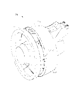
thrust. In that regard, these fans can be configured such that the. blades, at
one pitch
angle, generate an aftward directed bypass flow resulting in forward thrust,
and, at
another pitch angle, generate a forward directed bypass flow resulting in
reverse thrust.
However, in these known engines, the condition of the bypass flow is often
less than
optimal in both directions. As such, for gas turbine engines having variable
pitch fans, it
would be useful to improve the condition of the bypass flow.
BRIEF DESCRIPTION OF THE INVENTION
[0004] In one aspect, a gas turbine engine having a centerline axis is
provided.
The gas turbine engine includes a fan and a fan cowl assembly surrounding the
fan to
define a bypass duct configured to channel airflow for the fan. The fan cowl
assembly
includes a stationary cowl and a transcowl. The gas turbine engine further
includes a
-1-
CA 02912353 2015-11-19
278548A
plurality of actuators configured for displacing the transcowl relative to the
stationary
cowl. Each of the actuators is skewed relative to the centerline axis of the
engine.
[0005] In another aspect, a method of assembling a gas turbine engine having a
centerline axis is provided. The method includes providing a fan and
surrounding the fan
with a fan cowl assembly to define a bypass duct configured to channel airflow
for the
fan. The fan cowl assembly includes a stationary cowl and a transcowl, and the
method
further includes coupling the tanscowl to the stationary cowl via a plurality
of actuators
configured for displacing the transcowl relative to the stationary cowl. Each
of the
actuators is skewed relative to the centerline axis of the engine.
[0006] In another aspect, a gas turbine engine having a centerline axis is
provided. The gas turbine engine includes a variable pitch fan and a fan cowl
assembly
surrounding the fan to define a bypass duct configured to channel airflow for
the fan.
The fan cowl assembly includes a stationary cowl and a transcowl. The gas
turbine
engine further includes at least six actuators coupling the stationary cowl to
the transcowl
such that the transcowl is displaceable relative to the stationary cowl via
the actuators to
define an auxiliary inlet for airflow into the bypass duct. The
actuators are
circumferentially spaced apart from one another and are alternatingly skewed
relative to
the centerline axis so as to be triangulated.
BRIEF DESCRIPTION OF THE DRAWINGS
[0007] Figure 1 is a schematic representation of a gas turbine engine
operating
in forward thrust mode;
[0008] Figure 2 is a schematic representation of the gas turbine engine shown
in
Figure 1 operating in reverse thrust mode;
[0009] Figure 3 is a perspective view of an aft segment of the gas turbine
engine
shown in Figure 1 configured for the forward thrust mode of Figure 1;
-2-
CA 02912353 2015-11-19
278548A
[0010] Figure 4 is a side view of the aft segment configuration shown in
Figure 3;
[0011] Figure 5 is a perspective view of the aft segment shown in Figure 3 and
configured for the reverse thrust mode of Figure 2;
[0012] Figure 6 is a side view of the aft segment configuration shown in
Figure 5;
[0013] Figure 7 is a perspective view of an actuator assembly for converting
the
aft segment between the configurations shown in Figure 3 and Figure 5;
[0014] Figure 8 is a side view of an actuator of the actuator assembly shown
in
Figure 7;
[0015] Figure 9 is a diagram illustrating the actuator assembly shown in
Figure
7 when converting the aft segment between the configurations shown in Figure 3
and
Figure 5;
[0016] Figure 10 is a schematic representation of a hydraulic system for
operating the actuator assembly shown in Figure 7;
[0017] Figure 11 is a top view of the aft segment configuration shown in
Figure 5;
[0018] Figure 12 is a perspective view of the aft segment shown in Figure 3
with its core cowl open; and
[0019] Figure 13 is a back view of the open core cowl shown in Figure 12.
DETAILED DESCRIPTION OF THE INVENTION
[0020] The following detailed description sets forth a transcowl for a gas
turbine
engine and a method of assembling the same by way of example and not by way of
limitation. The description should clearly enable one of ordinary skill in the
art to make
-3-
CA 02912353 2015-11-19
278548A
and use the transcowl, and the description sets forth several embodiments,
adaptations,
variations, alternatives, and uses of the transcowl, including what is
presently believed to
be the best mode thereof. The transcowl is described herein as being applied
to a
preferred embodiment, namely a thrust reverser for a gas turbine engine.
However, it is
contemplated that the transcowl and the methods of assembling the transcowl
may have
general application in a broad range of systems and/or a variety of
commercial, industrial,
and/or consumer applications other than thrust reversers for gas turbine
engines.
[0021] Figures 1 and 2 are schematic illustrations of a gas turbine engine 100
having a fan 102 and a core 104 arranged in flow communication with one
another along
a centerline axis 106 of engine 100. Fan 102 provides air to core 104 which,
in turn,
drives fan 102 to produce thrust for engine 100. Fan 102 is a variable pitch
fan, meaning
that the pitch of its blades 108 can be selectively varied to generate forward
thrust or
reverse thrust for engine 100. A fan cowl assembly 110 surrounds fan 102 and
includes a
stationary cowl 112 and a transcowl 114 that collectively define a
substantially annular
bypass duct 116 about core 104 for channeling airflow for fan 102.
[0022] When engine 100 is in its forward thrust mode (Figure 1), transcowl 114
and stationary cowl 112 abut one another such that airflow enters bypass duct
116
through a forward inlet 118 of bypass duct 116, and exits bypass duct 116
through an aft
outlet 120 of bypass duct 116 (i.e., air flows through bypass duct 116 in a
forward to aft
direction). When engine 100 is in its reverse thrust mode (Figure 2), however,
transcowl
114 is axially spaced apart from stationary cowl 112 to create an auxiliary
inlet 122 for
air entering bypass duct 116. Notably, in the reverse thrust mode, forward
inlet 118
becomes a forward outlet 124, and aft outlet 120 becomes an aft inlet 126. As
such, air
flows into bypass duct 116 from aft inlet 126 and auxiliary inlet 122, and air
exits bypass
duct 116 through forward outlet 124 (i.e., air flows through bypass duct 116
in an aft to
forward direction). In this manner, auxiliary inlet 122 facilitates providing
airflow into
bypass duct 116 in a more controlled and stable manner than had the airflow
entered
bypass duct 116 from aft inlet 126 alone, since airflow entering bypass duct
116 from aft
-4-
CA 02912353 2015-11-19
278548A
inlet 126 tends to experience more flow separation and, therefore, tends to be
less
controlled than airflow entering bypass duct 116 through auxiliary inlet 122.
[0023] Figures 3 and 4 are perspective views of an aft segment 128 of gas
turbine engine 100, and aft segment 128 is configured for forward thrust mode
(Figure 1),
in that transcowl 114 is in abutment with stationary cowl 112. In Figures 5
and 6, on the
other hand, aft segment 128 is configured for reverse thrust mode (Figure 2),
in that
transcowl 114 is axially spaced apart from stationary cowl 112 to create
auxiliary inlet
122. Notably, engine 100 is provided with an actuator assembly 130 for
displacing
transcowl 114 relative to stationary cowl 112 in translation substantially
parallel to
centerline axis 106.
[0024] Figures 7 and 8 illustrate actuator assembly 130 in more detail. In the
exemplary embodiment, actuator assembly 130 includes six actuators 132 (a
minimum of
six actuators 132 equating to the six theoretical degrees of freedom of
transcowl 114 in its
displacement relative to stationary cowl 112). In other suitable embodiments,
actuator
assembly 130 may have more than six actuators 132. Notably, each of the
illustrated
actuators 132 is in the form of a linear actuator having a cylinder 134, a
piston 136
slidably inserted into cylinder 134, a first pin joint (e.g., a first
spherical bearing 138)
mounted on cylinder 134, and a second pin joint (e.g., a second spherical
bearing 140)
mounted on piston 136. First spherical bearings 138 connect actuators 132 to
stationary
cowl 112, and second spherical bearings 140 connect actuators 132 to transcowl
114. In
this manner, actuators 132 connect transcowl 114 to stationary cowl 112, and
function to
displace transcowl 114 relative to stationary cowl 112 when deployed.
[0025] As set forth in more detail below, actuators 132 are circumferentially
spaced apart in their arrangement between stationary cowl 112 and transcowl
114; and,
when displacing transcowl 114 relative to stationary cowl 112, each actuator
132 pivots
circumferentially during its transition from a stowed state 142 (in which
transcowl 114
abuts stationary cowl 112) and a deployed state 144 (in which transcowl 114 is
spaced
apart from stationary cowl 112). More specifically, when transcowl 114 is in
abutment
-5-
CA 02912353 2015-11-19
278548A
with stationary cowl 112, each actuator 132 is said to be in its stowed state
142; and,
when transcowl 114 is fully spaced from stationary cowl 112, each actuator 132
is said to
be in its deployed state 144. Notably, in Figures 7 and 8, each actuator 132
is shown in
both its stowed state 142 and its deployed state 144, which are separated by a
V-shaped
spacing 146 that represents the circumferential pivoting that each actuator
132 undergoes
during its transition from stowed state 142 to deployed state 144 as described
below.
[0026] Illustrated in Figure 9 is = a diagram of the configuration and
function of
actuators 132. In the diagram, the circumferential arrangement of actuators
132 has been
projected onto a plane (i.e., the annular formation of actuators 132 has been
separated at a
seam 148 and flattened for illustration purposes). In that regard, each
actuator 132 is
represented in its stowed state 142 by a stowed actuator line 150, and in its
deployed state
144 by a deployed actuator line 152. Moreover, centerline axis 106 of engine
100 is
represented by an axis line 154, and the difference in length between the
various stowed
actuator lines 150 and the various deployed actuator lines 152 along axis line
154
represents a displacement range 156 of transcowl 114.
[0027] It is apparent from the diagram that actuators 132 are
circumferentially
spaced apart about centerline axis 106 and are oriented in an alternatingly
skewed manner
relative centerline axis 106 and relative to one another. More specifically,
the first, third,
and fifth stowed actuator lines 150 (from left to right on the diagram) are
oriented in a
clockwise direction 158 in their forward-aft extension 163 so as to be skewed
relative to
(i.e., not parallel with) axis line 154. On the other hand, the second, third,
and sixth
stowed actuator lines 150 (from left to right on the diagram) are oriented in
a
counterclockwise direction 160 in their forward-aft extension 163 so as to be
skewed
relative to axis line 154. Oriented in this manner, a spacing 162 between
adjacent
actuators 132 is, in terms of the diagram, generally triangular in shape when
actuators
132 are in their stowed states 142. Moreover, it is apparent from the diagram
that
actuators 132 remain skewed and continue to have generally triangular spacing
162 in
their deployed states 144 as well.
-6-
CA 02912353 2015-11-19
278548A
[0028] It is also apparent from the diagram that, by virtue of being mounted
on
spherical bearings 138, 140, each actuator 132 is permitted to pivot in a
circumferential
direction (i.e., in clockwise direction 158 or counterclockwise direction 160)
when
transitioning from being stowed to being deployed. More specifically, in its
transition
from stowed state 142 to deployed state 144, each clockwise-oriented actuator
132 (i.e.,
each of the first, third, and fifth actuators 132) pivots in counterclockwise
direction 160,
and each counterclockwise-oriented actuator 132 (i.e., each of the second,
fourth, and
sixth actuators 132) pivots in clockwise direction 158. To the contrary, in
its transition
from deployed state 144 back to stowed state 142, each clockwise-oriented
actuator 132
pivots in clockwise direction 158, and each counterclockwise-oriented actuator
132
pivots in counterclockwise direction 160. Such pivoting motion is represented
in the
diagram by spacing 164 between each stowed actuator line 150 and it associated
deployed actuator line 152. Notably, within the construct of being
triangulated in such a
manner, actuators 132 may be oriented at any suitable angles relative to
centerline axis
106 (i.e., actuators 132 cannot all be oriented parallel to centerline axis
106). For
example, in terms of the diagram, the clockwise-oriented actuators 132 and the
counterclockwise-oriented actuators 132 may have their stowed actuator lines
150
respectively angled at about 16 and -16 relative to axis line 154, with
their deployed
actuator lines 152 being respectively angled at about 30 and -30 relative to
axis line 154
(such that spacing 164, or pivoting range, would be about 14 ).
[0029] By virtue of actuator assembly 130 having six actuators 132 oriented
and
pivotable in this manner, better stabilization of transcowl 114 in its
displacement relative
to stationary cowl 112 is facilitated. More specifically, because adjacent
actuators 132
are circumferentially angled in opposite directions, the support structure for
transcowl
114 is effectively triangulated, making the support structure more stable
(e.g., if actuators
132 were oriented parallel to one another and centerline axis 106, actuators
132 would be
more susceptible to bending in response to vertical and lateral loads applied
perpendicular to centerline axis 106). In other words, providing six
alternatingly-skewed,
fixed-length actuators 132 accounts for each of the six theoretical degrees of
freedom of
-7-
CA 02912353 2015-11-19
278548A
transcowl 114 which, in turn, results in a determinate solution for
positioning transcowl
114 in space. When fully extended, actuators 132 have a known length and,
therefore,
transcowl 114 has a determinate deployed position. Likewise, when retracted,
actuators
132 have a known length, and the stowed transcowl 114 has a determinate
position.
Notably, other than actuators 132 themselves, minimal guidance (e.g., no
slider tracks) is
provided for ensuring translation of transcowl 114 substantially parallel to
centerline axis
106.
[0030] Figure 10 illustrates a hydraulic system 166 for operating actuators
132.
In the exemplary embodiment, hydraulic system 166 includes a pump 168 and a
plurality
of conduits 170 for supplying hydraulic fluid from pump 168 to actuators 132
such that
each actuator 132 has its own dedicated conduit 170. In other embodiments,
conduits
170 may be arranged in any suitable manner that facilitates enabling system
166 to
function as described herein. While not shown in Figure 10, system 166 also
includes
another plurality of conduits for returning hydraulic fluid from actuators 132
back to a
suitable reservoir from which pump 168 draws fluid.
[0031] Notably, to facilitate displacement of transcowl 114 substantially
parallel
to centerline axis 106, actuators 132 should move at substantially the same
rate.
However, pumping hydraulic fluid along the various conduits 170 at
substantially the
same pressure does not, in and of itself, ensure substantially equal rates of
motion
amongst actuators 132 since each actuator 132 may have a different resistance
to motion.
Thus, a flow limiting member 172 is provided at the junction of each conduit
170 and
each cylinder 134 of the associated actuator 132. Flow limiting members 172
collectively facilitate movement of actuators 132 at substantially the same
rate despite
any variation in resistance from one actuator 132 to the next. In the
illustrated
embodiment, each flow limiting member 172 is in the form of a plate 174 having
an
orifice 176 with a diameter less than the diameter of its associated conduit
170 (e.g.,
conduit 170 may have a diameter of about 3/8", while orifice 176 may have a
diameter of
about 1/8"). Suitably, in other embodiments, flow limiting member 172 may have
any
-8-
CA 02912353 2015-11-19
278548A
configuration that facilitates enabling hydraulic system 166 to function as
described
herein.
[0032] In the exemplary embodiment, orifices 176 function as a collective unit
to facilitate applying substantially the same rate of fluid flow to pistons
136 despite any
inherent resistance to displacement of pistons 136 that may exist amongst
actuators 132.
More specifically, because orifices 176 are smaller than their associated
conduits 170, the
pressure drop across each orifice 176 adjusts to cause a pressure decrease in
actuators 132
that tend to experience less resistance, and an pressure increase in actuators
132 that tend
to experience more resistance. In other words, actuators 132 having pistons
136 that tend
to be displaced more easily experience an increase in the velocity of the
hydraulic fluid
passing through their orifices 176, which results in a greater pressure drop
across their
orifices 176 and, therefore, less pressure being applied to those pistons 136.
On the other
hand, actuators 132 having pistons 136 that tend to be displaced less easily
experience a
decrease in the velocity of the hydraulic fluid passing through their orifices
176, which
results in less of a pressure drop across their orifices 176 and, therefore,
more pressure
being applied to those pistons 136. Thus, actuators 132 experiencing lower
resistance to
displacement will tend to decelerate, and actuators 132 experiencing greater
resistance to
displacement will tend to accelerate. Hydraulic system 166 thereby establishes
a
tendency toward equal velocity and displacement amongst actuators 132 and, as
a result,
facilitates displacement of transcowl 114 in a more parallel manner relative
to centerline
axis 106. Moreover, because actuators 132 tend to be hydraulically
synchronized in such
a manner, actuator assembly 130 is not provided with a mechanical
synchronization
mechanism (e.g., a synchronization cable) coupling actuators 132 together to
facilitate
movement of actuators 132 in unison. Other embodiments of actuator assembly
130 may,
however, include such a mechanical synchronization mechanism.
[0033] Figure 11 illustrates that transcowl 114 is annular (i.e., tanscowl 114
extends in 360 ) so as to wrap over a top surface 180 of a pylon fairing 178
associated
with a pylon that suspends engine 100 from the wing of an aircraft. Referring
back to
Figures 4 and 6, being that top surface 180 of pylon fairing 178 is intended
to slide within
-9-
CA 02912353 2015-11-19
278548A
the annular shape of transcowl 114, top surface 180 of pylon fairing 178 is
contoured
(e.g., sloped downward) to mirror the interior contour of transcowl 114. As
such,
displacement of transcowl 114 is facilitated without interference from pylon
fairing 178.
Nevertheless, contact wear strips may suitably be placed on top surface 180
and/or the
side surfaces of pylon fairing 178 to aid in displacing transcowl 114 more
smoothly in the
event that transcowl 114 rubs against pylon fairing 178 mid-stroke due, for
example, to
gravity pulling transcowl 114 somewhat downward or a crosswind blowing
transcowl
114 somewhat sideways. Additionally, to facilitate minimizing interference
from pylon
fairing 178, transcowl 114 is provided with a cutout 182 in its forward edge
184 at the top
of its annulus, and a matching key 186 (i.e., a stationary filler piece) is
provided on
stationary cowl 112 and/or pylon fairing 178 for slidable insertion into
cutout 182.
Cutout 182 provides access to a tunnel formed in the top interior of transcowl
114
through which pylon fairing 178 may pass without interfering with transcowl
114.
Moreover, because key 186 is inserted into cutout 182 when transcowl 114 is in
abutment
with stationary cowl 112, key 186 occupies space in the tunnel, resulting in a
reduced
affect of the tunnel on the flow area of bypass duct 116 when auxiliary inlet
122 is
closed.
[0034] Figures 12 and 13 illustrate a core cowl 188 of core 104. In the
exemplary embodiment, core cowl 188 is provided with a pair of substantially
semi-
annular doors 190 that are hingedly openable away from one another in a
clamshell-like
manner to provide access to operational components 192 of core 104 for
servicing
operational components 192 without having to remove, open, disassemble, or
otherwise
manipulate fan cowl assembly 110.
[0035] The above-described embodiments facilitate providing improved airflow
into a bypass duct during reverse thrust mode of a gas turbine engine. The
above-
described embodiments also facilitate effective displacement of a transcowl
for a gas
turbine engine and, in that regard, facilitate structurally supporting the
transcowl in its
displacement without the use of cumbersome support structures such as slider
tracks.
Additionally, the embodiments facilitate establishing a tendency for equal
velocity and
-10-
CA 02912353 2015-11-19
278548A
displacement of actuators used to displace a transcowl. The embodiments
further
facilitate providing easier access to core operating components of a gas
turbine engine
within a core cowl without disturbing a fan cowl assembly that surrounds the
core cowl.
[0036] Exemplary embodiments of a transcowl and a method of assembling the
same are described above in detail. The methods and systems are not limited to
the
specific embodiments described herein, but rather, components of the methods
and
systems may be utilized independently and separately from other components
described
herein. For example, the methods and systems described herein may have other
industrial
and/or consumer applications and are not limited to practice with only gas
turbine engines
as described herein. Rather, the present invention can be implemented and
utilized in
connection with many other industries.
[0037] While there have been described herein what are considered to be
preferred and exemplary embodiments of the present invention, other
modifications of
these embodiments falling within the scope of the invention described herein
shall be
apparent to those skilled in the art.
-11-