Note : Les descriptions sont présentées dans la langue officielle dans laquelle elles ont été soumises.
SECTIONAL CONTROL CALIBRATION SYSTEM AND
METHOD
TECHNICAL FIELD
[0001] The present application relates generally to agricultural
implements, and
more specifically, to systems and methods for metering agricultural products.
BACKGROUND
[0002] Generally, agricultural implements (e.g., seeders) are towed
behind a tractor
or other work vehicle and deliver agricultural products (e.g., seed,
fertilizer, and/or
other particulate material) to a field. In some cases, agricultural implements
may also
be coupled to a product storage tank configured to store agricultural products
and
having a meter configured to regulate a flow of the agricultural products from
the
product storage tank to the implement. For example, the meter may meter the
agricultural products into multiple distribution lines that distribute the
agricultural
product to corresponding ground engaging tools disposed across a frame of the
agricultural implement for deposition of the agricultural product into the
soil.
[0003] Typical agricultural implements include a single meter or may
have multiple
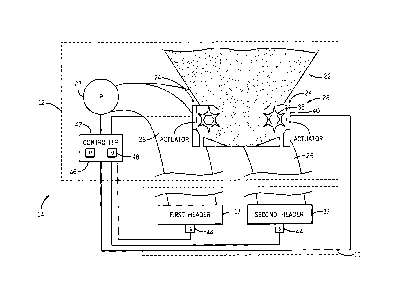
meters that are controlled together (e.g., rotate at the same rate or meter
the agricultural
product from the product storage tank into the multiple distribution lines at
the same
rate). This may lead to under seeded areas and/or product overlap, which may
in turn
result in wasted product or reduced overall yield.
SUMMARY
100041 Certain embodiments commensurate in scope with the present
disclosure are
summarized below. These embodiments are not intended to limit the scope of the
disclosure, but rather these embodiments are intended only to provide a brief
summary
of possible forms of the disclosure. Indeed, the disclosure may encompass a
variety of
forms that may be similar to or different from the embodiments set forth
below.
1
CA 2912896 2019-01-22
[0005] In one embodiment, a controller includes a memory and a processor.
The
processor being configured to access, in the memory, a first time relative to
activation
of a first meter module of a metering subassembly when a first pressure at a
first header
of an agricultural implement reaches a first target pressure and to access, in
the memory,
a second time relative to activation of a second meter module of the metering
subassembly when a second pressure at a second header of the agricultural
implement
reaches a second target pressure. The first and second meter modules are in
fluid
communication with the first and second headers, respectively. The processor
also
configured to control a first actuator to activate the first meter module
based at least in
part on the first time, and to control a second actuator to activate the
second meter
module based at least in part on the second time.
[0006] In a second embodiment, a controller includes a processor
configured to
instruct a first actuator to drive a first meter module of a metering
subassembly to
dispense agricultural product to a first header of an agricultural implement,
instruct a
second actuator to drive a second meter module of the metering subassembly to
dispense agricultural product to a second header of the agricultural
implement, receive
a first signal indicative of a first pressure within the first header and a
second signal
indicative of a second pressure within the second header, and determine a
first time
relative to activation of the first meter module when the first pressure
reaches a first
target pressure based on the first signal and a second time relative to
activation of the
second meter module when the second pressure reaches a second target pressure
based
on the second signal.
100071 In a third embodiment, a method includes metering agricultural
product to a
first header of an agricultural implement via a first meter module of a
metering
subassembly, receiving, at a processor, a first signal indicative of a first
pressure at the
first header, and determining, via the processor, a first time relative to
activation of the
first meter module when the first pressure reaches a target pressure based at
least in part
on the first signal.
2
CA 2912896 2019-01-22
BRIEF DESCRIPTION OF DRAWINGS
[0008] These and other features, aspects, and advantages of the present
disclosure
will become better understood when the following detailed description is read
with =
reference to the accompanying drawings in which like characters represent like
parts
throughout the drawings, wherein:
[0009] FIG. I is a side view of an embodiment of an agricultural
implement coupled
to an air cart that includes a control system;
[0010] FIG. 2 is a top view of an embodiment of the agricultural
implement and the
air cart of FIG. 1;
[0011] FIG. 3 is a schematic diagram of a portion of an embodiment of
the
implement and the air cart of FIG. 1;
[0012] FIG. 4 is a block diagram of an embodiment of the control system
of FIG. I;
j0013] FIG. 5 is a flow diagram of an embodiment of a process suitable
for
calibrating a target pressure at each header of the agricultural implement of
FIG. 1;
[0014] FIG. 6 is a flow diagram of an embodiment of a process suitable
for
calibrating a time at which the pressure at each header reaches the target
pressure; and
[0015] FIG. 7 is a flow diagram of an embodiment of a process suitable
for operating
meters independently according to calibrated times.
DETAILED DESCRIPTION
[0016] One or more specific embodiments of the present disclosure will
be
described below. In an effort to provide a concise description of these
embodiments,
all features of an actual implementation may not be described in the
specification. It
should be appreciated that in the development of any such actual
implementation, as in
any engineering or design project, numerous implementation-specific decisions
must
be made to achieve the developers' specific goals, such as compliance with
system-
3
CA 2912896 2019-01-22
related and business-related constraints, which may vary from one
implementation to
another. Moreover, it should be appreciated that such a development effort
might be
complex and time consuming, but would nevertheless be a routine undertaking of
design, fabrication, and manufacture for those of ordinary skill having the
benefit of
this disclosure.
[0017] When introducing elements of various embodiments of the present
disclosure, the articles "a," "an," "the," and "said- are intended to mean
that there are
one or more of the elements. The terms "comprising," "including,- and "having"
are
intended to be inclusive and mean that there may be additional elements other
than the
listed elements.
[0018] Uniformly controlling meters in agricultural implements with
different
length distribution lines may result in undesirable application of
agricultural product to
certain portions of the field, product overlap, and/or inadequate product
deposition,
which may in turn result in wasted product or reduced overall yield. There
exists a need
for a sectional control system that is configured to independently control
starting and
stopping of each meter according to respective calibration times to facilitate
appropriate
deposition of the agricultural product to the field.
[00191 Accordingly, the present disclosure relates to a sectional control
system that
may be used in an agricultural implement coupled to an air cart and that is
configured
to calibrate the operation of the meters independently to reduce overlap
and/or under
seeding of certain areas of a field, such as headlands. Headlands may refer to
the
borders of a field and are typically seeded first. After the headlands are
seeded,
operators may traverse the headlands with each pass of the field. Thus, it may
be
desirable to uniformly stop seeding (e.g., stop deposition of seeds into the
soil) when
the agricultural implement crosses headlands boundary and uniformly begin
seeding
(e.g., deposit seeds into the soil) when the implement exits the headlands
boundary.
However, it should be noted that, while headlands are used as an example area
for
purposes of discussion, the techniques disclosed herein may be applicable to
any area
of a field where agricultural product is distributed.
4
CA 2912896 2019-01-22
100201 In some embodiments, the meters in the air cart are independently
driven and
controlled based on times (e.g., calibration times) at which an amount of
agricultural
product at respective headers reaches a target amount. In some embodiments,
the
amount of agricultural product is indicated by a measured pressure at the
header, air
flow rate at the header, or some combination thereof via one or more sensors.
The
calibration times are related to the time it takes the agricultural product to
travel from
the meter to its respective header. This may enable deposition of agricultural
product
into the soil to start and stop at substantially the same time across a width
of the
agricultural implement and/or to start and stop from each section of ground
engaging
tools as each respective section crosses a designated boundary. The
calibration times
may be obtained from a storage medium (e.g., memory) or determined while the
air cart
and agricultural implement are in use. During operation, a controller may
gather
information (e.g., weather conditions, or the like) and adjust the calibration
times
accordingly. According to an aspect of the disclosure, the operation of the
meters using
the calibrated times may be initiated automatically by location data obtained
by a global
positioning system (GPS), manually by operator input, or some combination
thereof.
100211 In some embodiments, one or more pressure sensors may be located
at each
header. It should be noted that the calibration techniques disclosed herein
may include
any number of headers (e.g., 1, 2, 3,4, 5, 6, etc.). The controller may begin
calibration
by determining a target pressure for each header. To achieve this, the
controller may
run each meter and the product flow at each header may be monitored (e.g., via
a
sensor). When a desired product flow is detected at each header (e.g., by the
height of
product flow), each pressure sensor may measure the pressure at each header
and send
a signal indicative of the pressure to the controller, which may set the
pressure as the
target pressure for each header. It should be noted, that in some embodiments,
the target
pressure is preset and stored in memory. Then, the controller may calibrate
the timing
of operation for each meter. To achieve this, the controller may run the
meters again
and monitor the pressure (e.g., via the pressure sensors) at each header. The
controller
may record the time (e.g., relative times) at which each header reaches its
target
pressure. It should be appreciated that it may take longer for the headers on
the outside
sections (e.g., disposed at a laterally outward position of the implement) of
the
CA 2912896 2019-01-22
implement to reach the target pressure due to longer distribution lines than
the center
sections (e.g., disposed at a laterally inward position of the implement).
However,
using the relative times at which each header reaches the target pressure, the
controller
may independently control the meters so that agricultural product is deposited
at
substantially the same time or cut-off at substantially the same time across
the width of
the implement and/or as respective sections of the agricultural implement
approach
and/or cross designated boundaries.
[0022] With the
foregoing in mind, FIG. 1 is a side view of an embodiment of an
agricultural implement 10 (e.g., a seeding implement) coupled to an air cart
12 having
a control system 14. The implement 10 includes multiple row units 16 and
multiple
distribution headers 17 supported by a frame 18. Each distribution header 17
is
configured to receive agricultural product (e.g., seed, fertilizer, and/or
other particulate
material) from the air cart 12 and to route the product to each row unit 16.
The row
units 16 may be configured to deposit the agricultural product into the soil
as the
implement 10 travels across a field. As shown, the air cart 12 is coupled to
the
implement 10 via the frame 18. The air cart 12 may include one or more product
storage
tanks 22 configured to store one or more agricultural products. Each product
storage
tank 22 is coupled to a corresponding metering subassembly 28, which includes
multiple meter modules 24 each coupled to a corresponding primary product
distribution line 26 (e.g., primary lines) that is configured to distribute
agricultural
product to one or more corresponding headers 17 of the implement 10. The meter
modules 24 may be in fluid communication with the headers 17. Each meter
module
24 may include an actuator and a meter roller, where the actuator may be
configured to
drive the meter roller to dispense agricultural product from the storage tanks
22. In
some embodiments, the meter module 24 may include a gate and the actuator may
drive
the gate. The meter modules 24 may be controlled by the control system 14. An
air
source 27 provides an air flow to each fate primary lines 26. The metered
agricultural
product is entrained within the air flow and pneumatically transferred to the
one or more
corresponding headers 17 of the implement 10. While two meter modules 24 and
two
primary lines 26 are shown for clarity, it should be appreciated that, in
certain
embodiments each metering subassembly 28 may include at least 4, 6, 8, 10, 12,
14, 16,
6
CA 2912896 2019-01-22
18, 20, or more meter modules 24 and/or primary lines 26. Furthermore, one
metering
module 24 may provide the agricultural product to one or more primary lines 26
(e.g.,
a subset of the primary lines 26). Additionally, while two headers 17 are
shown for
clarity, it should be appreciated that, in some embodiments the implement 10
may
include at least 1, 2, 4, 6, 8, 10, 12, or more headers 17. It should also be
appreciated
that while two row units 16 are shown for clarity, in certain embodiments, the
implement 10 may include at least 4, 6, 8, 10, 12, 14, 16, 18, 20, or more row
units 16,
and furthermore, that each primary line 26 may provide the agricultural
product to any
suitable number (e.g., 1, 2, 3,4, 5, 6, 7, 8, 9, 10, or more) of row units 16.
Similarly,
while one product storage tank 22 is illustrated, it should be appreciated
that, in certain
embodiments the air cart 12 may include at least 2, 3, 4, 5, 6 or more product
storage
tanks 22.
[0023] As discussed in more detail below, the control system 14 may be
configured
to calibrate the activation timing of the meter modules 24 so that headers 17
on the
outer sections of the frame 18 receive a suitable amount of product to
dispense at
substantially the same time as the headers 17 in the center sections of the
frame 18.
Likewise, the control system 14 may be configured to calibrate the
deactivation timing
of the meter modules 24 so that all headers 17 cease receiving and
distributing product
at substantially the same time. In some embodiments, the calibration times may
enable
the control system 14 to independently control the meter modules 24 such that
the
product is distributed to the field according to a designated boundary. The
control
system 14 may be configured to receive inputs from a pressure sensor and
determine
the relative times at which each header reaches a target pressure. That is,
the times may
be relative to the activation of the meter modules 24. The control system 14
may
independently operate the meter modules 24 based on the relative times. Also,
the
control system 14 may adjust the times during operation of the agricultural
implement
if conditions change or upon demand. In some embodiments, the control system
14
may activate or deactivate the meter modules 24 based on location data
provided by the
GPS or based on operator input.
[0024] FIG. 2 illustrates a top view of the agricultural implement 10
coupled to the
air cart 12 of FIG. 1. As depicted, the implement 10 includes six sections 30
attached
7
(CA 2912896 2019-01-22
to the frame 18 of the implement 10. Each section 30 includes multiple row
units 16
attached to crossbars 32. Laterally displacing the row units 16 in the
illustrated manner
may enable a dense disbursement of product across a wide swath of soil. In
addition,
each section 30 may include one header 17 that receives agricultural product
metered
by a respective meter module 24 into a respective attached primary line 26. As
such,
there may be six meter modules 24 and six primary lines 26 in the depicted
embodiment,
one for each header 17. The headers 17 may route the product to the respective
multiple
row units 16 to distribute the product to the ground. In some embodiments,
each section
30 may include any number of suitable headers 17 and/or row units 16. The
sections
30 may have any suitable configuration.
[0025] It should be appreciated that the elapsed time for product to
reach the outer
sections 34 on the frame 18 may be longer than the inner sections 36 near the
center of
the frame 18. Thus, the control system 14 may calibrate the timing of
activating and
deactivating the meter modules 24, as described in detail below, to reduce
overlap of
product or under seeding areas of a field, such as headlands. To achieve this,
each
header 17 may include one or more sensors, such as a pressure sensor, air flow
sensor,
and the like. During calibration, the pressure sensor may detect the pressure
at the
header 17 and send the data to the control system 14. When the pressure at
each header
17 reaches a target pressure, the control system 14 may record the elapsed
time and
control the meter modules 24 according to the respective relative elapsed
times.
[0026] FIG. 3 is a schematic diagram of a portion of an embodiment of the
implement 10 and the air cart 12. To facilitate discussion, one product
storage tank 22
and its corresponding metering subassembly 28 is shown. However, it should be
understood that the air cart 12 may include any suitable number of storage
tanks 22,
and the control system 14 may provide one metering subassembly 28 for each
storage
tank 22. As shown, the metering subassembly 28 includes two meter modules 24
(e.g.,
a first metering module and a second metering module), although the metering
subassembly 28 may include any suitable number of meter modules 24, as noted
above.
In the illustrated embodiment, each meter module 24 is configured to meter the
agricultural product into a corresponding primary line 26. The air source 27
may move
air past the meter module 24 in each primary line 26 to the header 17. The air
source
8
CA 2912896 2019-01-22
27 may include a fan, pump, or blower powered by an electric or hydraulic
motor. As
the meter module 24 dispenses product into the air flow in each primary line
26, each
primary line 26 is configured to direct the agricultural product to a
corresponding
distribution header 17 of the implement 10, and the distribution header 17 is
configured
to distribute the agricultural product into one or more corresponding
secondary lines
extending to a corresponding row unit 16. As depicted, two headers 17 are
shown (e.g.,
a first header and a second header), each header 17 being connected to a
separate
primary line 26 and metering module 24. It should be noted that any suitable
number
of headers 17 may be used. Each meter module 24 and corresponding primary line
26
may thus provide agricultural product to separate sections 30 of the implement
10, as
noted above. Because each meter module 24 may be separately controlled, the
product
may be disbursed into longer primary lines 26 that deliver the product to
headers 17 on
the outside of the implement 10 before metering product to the shorter primary
lines 26
that deliver product to headers 17 at the center portions of the implement, in
some
embodiments. Also, meter modules 24 connected to longer primary lines 26 may
be
deactivated prior to meter modules 24 connected to shorter primary lines so
that the
cut-off of product delivery to ground may be substantially concurrently, in
some
embodiments.
100271 Each meter
module 24 includes a meter roller 38 (e.g., meter) and an actuator
40 (e.g., motor) configured to actuate (e.g., drive rotation of) the
respective meter 38.
That is, each motor 40 may drive rotation of a drive shaft coupled to the
respective
meter 38. Although each meter module 24 includes the motor 40 in the
illustrated
embodiment, the respective meter roller 38 of each metering module 24 may be
driven
into rotation via any suitable mechanism. The control system 14 also includes
a
controller 42 that may be coupled to each meter subassembly 28. The controller
42 is
configured to control each motor 40 based on the calibration times and/or one
or more
factors, such as location of the agricultural implement, speed of the
agricultural
implement, weather, and the like. In certain embodiments, the controller 42 is
an
electronic controller having electrical circuitry configured to process
signals (e.g.,
signals indicative of pressure at each header 17, weather conditions, speed,
location)
from one or more sensors 44 (e.g., pressure, speed, weather condition, GPS).
In some
9
CA 2912896 2019-01-22
embodiments, a pressure sensor 44 may be located at each header 17 and
configured to
measure the pressure at the header 17 and transmit the pressure to the
controller 42. For
example, as illustrated, the pressure sensors 44 may be located at the bottom
of the
headers 17. The controller 42 may also be communicatively coupled to the air
source
27 to control the air flow.
[0028] In the illustrated embodiment, the controller 42 includes a
processor 46, such
as a microprocessor, and a memory device 48. The controller 42 may also
include one
or more storage devices and/or other suitable components. The processor 46 may
be
used to execute software, such as software for controlling the control system
14.
Moreover, the processor 46 may include multiple microprocessors, one or more
"general-purpose" microprocessors, one or more special-purpose
microprocessors,
and/or one or more application specific integrated circuits (ASICS), or some
combination thereof. For example, the processor 46 may include one or more
reduced
instruction set (RISC) or complex instruction set (CISC) processors.
[0029] The memory device 48 may include a volatile memory, such as
random
access memory (RAM), and/or a nonvolatile memory, such as ROM. The memory
device 48 may store a variety of information and may be used for various
purposes. For
example, the memory device 48 may store processor-executable instructions
(e.g.,
firmware or software) for the processor 46 to execute, such as instructions
for
controlling the control system 14. The storage device(s) (e.g., nonvolatile
storage) may
include read-only memory (ROM), flash memory, a hard drive, or any other
suitable
optical, magnetic, or solid-state storage medium, or a combination thereof.
The storage
device(s) may store data (e.g., calibration times of the meters data, target
pressures at
each header data, location data, implement speed data, weather condition data,
agricultural product type data, or the like), instructions (e.g., software or
firmware for
controlling the control system 14, or the like), and any other suitable data.
[0030] FIG. 4 is a block diagram of an embodiment of the control system
14. As
illustrated, the control system 14 includes a user interface 50 including a
display 52,
manual controls 54, the controller 42 including the processor 46 and the
memory device
48, the meter modules 24 including the actuators 40 and the meter rollers 38,
and a
CA 2912896 2019-01-22
spatial locating device/GPS 56. In the illustrated embodiment, the user
interface 50
may be communicatively coupled to the controller 42. The user interface 50 may
be
configured to accept operator input, such as selecting or inputting a type of
agricultural
product to dispense, a terrain type to work, and so forth. The user interface
50 may also
enable an operator to request the control system 14 to recalibrate at any time
the
operator determines that recalibration is desirable. In certain embodiments,
the user
interface includes the display 52 configured to present information to the
operator, such
as whether the control system 14 is activating or deactivating meter modules
24, a
geographic location of the implement 10 and air cart 12, a speed of the
implement 10
and air cart 12, weather conditions, among other things.
[0031] As
illustrated, the control system 14 includes manual controls 54 configured
to enable an operator to control the control system 14 at any time during
operation. The
manual controls 54 may enable the operator to manually instruct the control
system 14
to operate the meter modules 24 at any desired area in a field. For example,
if the
implement 10 is approaching a certain boundary, such as a headland, the
operator may
manually initiate disbursement of agricultural product, and the control system
14 may
use the calibration times information to independently operate the meter
modules 24
accordingly. In some instances, the meter modules 24 that supply agricultural
product
to the outside headers 17 of the implement may be activated first (e.g., based
on a first
calibration time) and then the meter modules 24 that supply product to the
center
headers 17 may be activated (e.g., based on a second calibration time).
Similarly, if the
operator manually deactivates the disbursement, the control system 14 may
deactivate
the meter modules 24 that supply product to the outside headers 17 of the
implement
since the product will take longer to reach the headers 17 than the center
headers 17
with shorter primary lines 26. In addition, the manual controls 54 may include
manual
steering control, manual transmission control, and/or manual braking control,
among
other controls. In the
illustrated embodiment, the manual controls 54 are
communicatively coupled to the controller 42.
[0032] In the
illustrated embodiment, the control system 14 may include a spatial
locating device/GPS 56 (e.g., GPS). The GPS 56 may be configured to determine
the
location and position of the implement 10 and the air cart 12. In certain
embodiments,
11
CA 2912896 2019-01-22
the GPS 56 may be configured to determine the location and position of the
implement
and the air cart 12 relative to a fixed point within a field (e.g., via a
fixed radio
transceiver). Accordingly, the GPS 56 may be configured to determine the
location and
position of the implement 10 and the air cart 12 relative to a fixed global
coordinate
system or a fixed local coordinate system. As illustrated, the GPS 56 is
communicatively coupled to the controller 42. The location and position
information
provided by the GPS 56 to the controller 42 may be used by the processor 46 to
determine when to activate and/or deactivate the meter modules 24 based on the
calibration times information. For example, if the data from the GPS 56
indicates that
the implement 10 is about to exit a headlands section, the controller 42 may
activate the
meter modules 24 coupled to the headers 17 that take longer to reach the
target pressure
first (e.g., the laterally outer headers 17) and then activate the meter
modules 24 coupled
to the headers 17 that take less time to reach the target pressure (e.g., the
laterally inner
headers 17) based on respective calibration times. In this way, the headers 17
across
the width of the implement 10 output the product to the ground as the
implement crosses
the boundary of the headlands, for example. The GPS 56 may also provide
information
indicating areas of the field that have already been seeded to enable the
control system
14 to automatically shut off the meter modules 24 using the calibration times
to block
overlapping of product. It should be appreciated, that the process of
controlling the
meter modules 24 with the control system 24 may occur automatically based on
location
and position information received from the GPS 56. Alternatively, as noted
above, the
process may be initiated or turned off manually at any time by the operator.
[0033] The
controller 42 may be configured to receive signals from the
communicatively coupled sensors 44. The sensors 44 may include one or more air
flow
sensors 58, pressure sensors 60, speed sensors 62, weather conditions sensors
64, and
the like. The air flow sensors 58 may be located at the headers 17, at the air
source 27,
or at any suitable position along the air flow path in the primary lines 26.
The air flow
sensors 58 may be configured to measure the amount of air flow and transmit a
signal
indicative of the air flow level to the controller 42. As previously
mentioned, one or
more pressure sensors 60 may be located at each header 17 in any suitable
place to
measure pressure, such as at the bottom of the header 17. The pressure sensors
60 may
12
CA 2912896 2019-01-22
measure the amount of pressure at each header 17 and transmit a signal
indicating such
to the controller 42. In some embodiments, as described in detail below, the
pressure
measured at the time when product flow is at a desired flow may be set as a
target
pressure for a particular header 17 by the controller 42. The controller 42
may time
how long it takes for each header 17 to reach its respective target pressure
and use that
timing information to independently control the meter modules 24 as desired.
[0034] In the illustrated embodiment, the speed sensors 62 may be
configured to
measure the speed of the implement 10 and/or the air cart 12. The speed may be
used
by the controller 42 to determine when to activate and/or deactivate the meter
modules
24 (e.g., based on when the sections 30 will cross the designated boundary).
In some
embodiments, the speed of the implement 10 and the air cart 12 may influence
the
amount of agricultural product to dispense, which may affect the rotational
speed of the
meter rollers 38, the air flow output by the air source 27, and so forth. For
example,
more agricultural product may be dispensed when the implement 10 is traveling
at
higher speeds than lower speeds to ensure that sufficient product reaches the
ground.
Thus, in some embodiments, the speed of the implement 10 and/or the air cart
12 may
be used by the controller 42 to activate or deactivate and/or to control the
metering rate
of the meter modules 24.
[0035] As illustrated, the weather condition sensors 64 may also send
signals to the
controller 42. The weather conditions measured by sensors 64 may include the
temperature, humidity level, precipitation, and so forth. The weather
conditions may
affect the agricultural product and the efficiency with which the product
flows through
the primary lines 26, for example, and thus may affect how the controller 42
controls
the distribution of the product. For example, humidity may cause the
agricultural
product to clump or stick together and, as a result, air flow may need to be
increased to
attain a sufficient amount of product distribution and/or the calibration
times may need
to be adjusted to account for the weather conditions. Thus, in some
embodiments, the
controller 42 may accept the weather condition as an input when determining
the
calibration times of the meter modules 24.
13
CA 2912896 2019-01-22
[0036] FIG. 5 is a flow diagram of an embodiment of a process 66 suitable
for
calibrating a target pressure at each header 17 of the implement 10. Portions
of the
process 66 may be implemented as processor-executable instructions stored on
the
memory device 48. The process 66 may include running the meter modules 24 to
deliver agricultural product to each header 17 (process block 68), monitoring
the
product flow (e.g., by height of emitted product or other characteristic)
(process block
70), determining whether a desired product flow is observed at each header 17
(decision
block 72), and, if so, measuring the pressure at each header 17 to determine a
target
pressure (process block 74), or, if not, continuing to monitor the product
flow (process
block 70). In some embodiments, the target pressure calibration process 66 may
be
performed the first time the implement 10 is operational, such as the first
trip across the
field, or at any desirable time. It should be noted that in some embodiments,
the target
pressure at each header 17 is preset and stored in the memory device 48.
[0037] Starting with process block 68, the controller 42 may instruct the
meter
modules 24 to dispense product into the primary lines 26 to be delivered via
the air flow
from the air source 27 to the headers 17. The controller 42 may instruct the
air source
27 to increase or decrease the air flow as desired until a sufficient product
flow is
obtained. Thus, the process 66 may include monitoring the product flow at each
header
17 (process block 70). In some embodiments, the product flow may be observed
by the
operator or measured via a sensor, such as an optical, contact, or flow sensor
from each
header 17. In decision block 72, when the operator observes or sensor detects
product
flowing from each header 17 at a desired height, such as 4", 5", 6", a foot,
and so forth,
the control system 14 may measure the pressure at each header 17 by obtaining
a
reading from the pressure sensors 60. It should be understood that the
pressure at each
header 17 may be consistent with one another or the pressure may vary based on
whether it is desirable to have certain headers 17 dispense more or less
product than
other headers 17. The controller 42 may set the measured pressure as the
target pressure
for each of the headers 17 (process block 74). Also, in some embodiments, a
threshold
range of target pressures may be determined that includes the measured
pressure within
the range and any one of the target pressures within the range may be suitable
for each
header 17 during operation.
14
CA 2912896 2019-01-22
100381 FIG. 6 is a flow diagram of an embodiment of a process 76 suitable
for
calibrating a time at which the pressure at each header 17 reaches its target
pressure. It
should be noted that the timing calibration process 76 may use the target
pressures for
each header 17 as determined in process 66 or may use target pressures that
are preset
and stored in the memory device 48. The process 76 may be implemented as
processor-
executable instructions stored on the memory device 48. As previously noted,
the
process 76 for establishing calibration times for each meter module 24 may be
performed at any desirable time, such as when the implement 10 and air cart 12
first
become operational during the first trip across the field. Also, the process
76 may be
initiated automatically or by operator input. In some embodiments, the process
76 may
include running the meter modules 24 to deliver product to headers 17
(controlling the
actuators in the meter modules 24) (process block 78), monitoring the pressure
at each
header 17 (process block 80), recording the time (e.g., relative time) at
which each
header 17 reaches the target pressure (process block 82), and operating meter
modules
24 independently according to the respective recorded times (process block
84). In an
embodiment, the process 76 may be repeated for turning off the meter modules
24. For
example, the controller 42 may turn off the meter modules 24, monitor the
pressure at
each header 17, and record the time (e.g., relative time) at which each header
reaches
zero pressure. The determined delay time may be used by the controller 42 to
independently operate the meter modules 24 accordingly.
100391 Starting with process block 78, the controller 42 may instruct the
meter
modules 24 to dispense product into the primary lines 26 to be delivered via
the air flow
to the headers 17. In some embodiments, the controller 42 may instruct the air
source
27 to output air, and the meter module 24 to distribute product, at the same
rate that the
desired product flow was obtained. The controller 42 may monitor the pressure
at each
header 17 (process block 80) by continuously or periodically receiving signals
indicative of pressure from the one or more pressure sensors 60 at each header
17. The
controller 42 may record the elapsed time it takes (e.g., the calibration
times) each
header 17 to reach the target pressure in the memory device 48 for later use
(process
block 82). The controller 42 may determine the calibration time for each
header 17
CA 2912896 2019-01-22
and, as the implement 10 and air cart 12 traverse the field, the controller 42
may operate
the meter modules 24 independently according to the recorded calibration
times.
[0040] To illustrate how the calibration times may be used by the
controller 42, by
way of example, it may take the headers 17 in the outside sections 30 of the
frame 18
ten seconds to reach the target pressure and it may take the headers 17 in the
center
sections 30 of the frame 18 five seconds to reach the target pressure. When
the
controller 42 determines the implement 10 is nearing a boundary where seeding
is to
be activated based on GPS data, for example, the controller 42 may instruct
the meter
modules 24 that supply product to the headers 17 in the outside sections 30 to
distribute
product to the headers 17 when the implement 10 is ten seconds away from the
boundary (accounting for speed, weather, and the like). Then, when the
implement 10
is five seconds away from the boundary, the controller 42 may instruct the
meter
modules 24 that supply product to the headers 17 in the center sections 30 to
distribute
product to the headers 17. Accordingly, the headers 17 in the outside sections
30 and
the center sections 30 of the frame 18 may reach the target pressures at
substantially the
same time so a uniform deposition of product to the soil is attained when the
implement
crosses the boundary.
[0041] FIG. 7 is a flow diagram of an embodiment of a process 86 for
operating the
meter modules 24 independently according to calibration times. The process 86
may
be implemented as processor-executable instructions stored on the memory
device 48.
The process 86 may be performed automatically by the control system 14 as the
implement 10 and air cart 12 traverse the field. In some embodiments, the
process 86
may be initiated by operator input. The process 86 may include receiving speed
data
(process block 88), receiving calibration time data (process block 90),
receiving
location information (process block 92), adjusting calibration times for
activating/deactivating each meter module 24 (process block 94), and
activating/deactivating each meter module 24 based on the adjusted calibration
times
(process block 96).
10042] Beginning with process block 88, as previously noted, the
controller 42 may
receive speed data from a speed sensor 62 that measures the speed of the
implement 10
16
CA 2912896 2019-01-22
and/or the air cart 12. The speed of the implement 10 and the air cart 12 may
affect the
density of product that is distributed by the implement 10. Also, the speed
may be
considered by the controller 42 when determining when to activate/deactivate
the meter
modules 24 based on the calibration times. In process block 90, the controller
42 may
receive the calibration time data related to how long it takes each header 17
to reach the
target pressure when the respective meter module 24 is activated or
deactivated. For
example, the calibration time data may include a first calibration time at
which a first
header reaches the target pressure, a second calibration time at which a
second header
reaches the target pressure, and so forth. The calibration time data may be
dynamically
calibrated as discussed above regarding process 76, or, in some embodiments,
the
calibration time data may accessed in the memory device 48 as preset timing
information or from previous calibrations. In process block 92, the controller
42 may
receive information related to the location of the implement 10 from the GPS
56. The
location data may be used by the controller 42 in conjunction with the
calibration times
to determine when to activate/deactivate the meter modules 24. For example,
the
location information may indicate that a boundary is approaching where seeding
should
be turned on or off. In some embodiments, the location information may
indicate
portions of a field that have already been seeded and the control system 14
may refrain
from seeding those areas again or the operator may cease operation of seeding
in an
area that is already seeded. Thus, as may be appreciated, some inputs received
by the
controller 42 may include the speed data, the calibration time data, and the
location
information. As previously noted, other inputs may be considered by the
controller 42,
such as the humidity level, air flow, and the like.
100431 Accounting
for certain inputs, such as the humidity level, air flow, product
type, and the like, in process block 94, the controller 42 may adjust the
calibration times
for turning on/off each meter module 24. Then, in process block 96, the
controller 42
may turn on/off each meter module 24 based on the calibration times or
adjusted
calibration times set by the controller 42. The process 86 may provide uniform
distribution of product from each header 17 at substantially the same time
regardless of
primary line 26 length, uniform cessation of product distribution from each
header 17
at substantially the same time, or both. Furthermore, the process 86 may
enable precise
17
CA 2912896 2019-01-22
. .
product deposition into the soil according to designated boundaries (e.g.,
headland
boundaries or other designated boundaries defining regions of the field,
preseeded
regions, or the like).
[0044] While only certain features of the subject matter have
been illustrated and
described herein, many modifications and changes will occur to those skilled
in the art.
18
CA 2912896 2019-01-22