Note : Les descriptions sont présentées dans la langue officielle dans laquelle elles ont été soumises.
CA 02914023 2015-12-03
1
ROPE FOR A HOISTING DEVICE, ELEVATOR AND USE
This application is a divisional of Canadian Patent Appli-
cation No. 2,711,074, filed on January 15, 2009.
The claims of the present application are directed to a
rope for an elevator and an elevator.
Accordingly, the retention of any features which may be
more particularly related to the parent application or a
separate divisional thereof should not be regarded as ren-
dering the teachings and claiming ambiguous or inconsistent
with the subject matter defined in the claims of the divi-
sional application presented herein when seeking to inter-
pret the scope thereof and the basis in this disclosure for
the claims recited herein.
FIELD OF THE INVENTION
The present invention relates to a hoisting device rope, to
an elevator and to a use of the hoisting device rope as the
hoisting rope of an elevator.
BACKGROUND OF THE INVENTION
Elevator ropes are generally made by braiding from metallic
wires or strands and have a substantially round cross-
sectional shape. A problem with metallic ropes is, due to
the material properties of metal, that they have a high
weight and a large thickness in relation to their tensile
strength and tensile stiffness. There are also prior-art
belt-like elevator ropes which have a width larger than
their thickness. Previously known are e.g. solutions in
which the load-bearing part of a belt-like elevator hoist-
ing rope consists of metal wires coated with a soft materi-
al that protects the wires and increases the friction be-
tween the belt and the drive sheave. Due to the metal
wires, such a solution involves the problem of high weight.
On the other hand, a solution described in specification
EP1640307 A2 proposes the use of aramid braids as the load-
bearing part. A problem with aramid material is mediocre
CA 02914023 2015-12-03
2
tensile stiffness and tensile strength. Moreover, the be-
havior of aramid at high temperatures is problematic and
constitutes a safety hazard. A further problem with solu-
tions based on a braided construction is that the braiding
reduces the stiffness and strength of the rope. In addi-
tion, the separate fibers of the braiding can undergo move-
ment relative to each other in connection with bending of
the rope, the wear of the fibers being thus increased. Ten-
sile stiffness and thermal stability are also a problem in
the solution proposed by specification PCT/FI97/00823, in
which the load-bearing part used is an aramid fabric sur-
rounded by polyurethane.
SUMMARY OF THE INVENTION
The present invention reduces the above-mentioned drawbacks
of prior-art solutions. The present invention improves the
roping of a hoisting device, particularly a passenger ele-
vator.
The aim of the invention is to produce one or more the fol-
lowing advantages, among others:
- A rope that is light in weight and has a high ten-
sile strength and tensile stiffness relative to its
weight is achieved.
- A rope having an improved thermal stability against
high temperatures is achieved.
- A rope having a high thermal conductivity combined
with a high operating temperature is achieved.
- A rope that has a simple belt-like construction and
is simple to manufacture is achieved.
- A rope that comprises one straight load-bearing part
or a plurality of parallel straight load-bearing
parts is achieved, an advantageous behavior at bend-
ing being thus obtained.
- An elevator having low-weight ropes is achieved.
- The load-bearing capacity of the sling and counter-
weight can be reduced.
CA 02914023 2015-12-03
3
- An elevator and an elevator rope are achieved in
which the masses and axle loads to be moved and ac-
celerated are reduced.
- An elevator in which the hoisting ropes have a low
weight vs. rope tension is achieved.
- An elevator and a rope are achieved wherein the am-
plitude of transverse vibration of the rope is re-
duced and its vibration frequency increased.
- An elevator is achieved in which so-called reverse-
bending roping has a reduced effect towards shorten-
ing service life.
- An elevator and a rope with no discontinuity or cyclic
properties of the rope are achieved, the elevator rope
being therefore noiseless and advantageous in re-
spect of vibration.
- A rope is achieved that has a good creep resistance,
because it has a straight construction and its geom-
etry remains substantially constant at bending.
- A rope having low internal wear is achieved.
- A rope having a good resistance to high temperature
and a good thermal conductivity is achieved.
- A rope having a good resistance to shear is
achieved.
- An elevator having a safe roping is achieved.
- A high-rise elevator is achieved whose energy con-
sumption is lower than that of earlier elevators.
In elevator systems, the rope of the invention can be used
as a safe means of supporting and/or moving an elevator
car, a counterweight or both. The rope of the invention is
applicable for use both in elevators with counterweight and
in elevators without counterweight. In addition, it can al-
so be used in conjunction with other hoisting devices, e.g.
as a crane hoisting rope. The low weight of the rope pro-
vides an advantage especially in acceleration situations,
because the energy required by changes in the speed of the
rope depends on its mass. The low weight further provides
CA 02914023 2015-12-03
4
an advantage in rope systems requiring separate compensat-
ing ropes, because the need for compensating ropes is re-
duced or eliminated altogether. The low weight also allows
easier handling of the ropes.
Inventive embodiments of the present invention are presented
in the description part and drawings of the present applica-
tion. The inventive content disclosed in the application can
also be defined in other ways than is done in the claims be-
low. The inventive content may also consist of several sepa-
rate inventions, especially if the invention is considered
in the light of explicit or implicit sub-tasks or with re-
spect to advantages or sets of advantages achieved. In this
case, some of the attributes contained in the claims below
may be superfluous from the point of view of separate in-
ventive concepts. The features of different embodiments of
the invention can be applied in connection with other em-
bodiments within the scope of the basic inventive concept.
According to the invention, the width of the hoisting rope
for a hoisting device is larger than its thickness in a
transverse direction of the rope. The rope comprises a
load-bearing part made of a composite material, which com-
posite material comprises non-metallic reinforcing fibers
in a polymer matrix, said reinforcing fibers consisting of
carbon fiber or glass fiber. The structure and choice of
material make it possible to achieve low-weight hoisting
ropes having a thin construction in the bending direction,
a good tensile stiffness and tensile strength and an im-
proved thermal stability. In addition, the rope structure
remains substantially unchanged at bending, which contrib-
utes towards a long service life.
In an embodiment of the invention, the aforesaid reinforc-
ing fibers are oriented in a longitudinal direction of the
rope, i.e. in a direction parallel to the longitudinal di-
CA 02914023 2015-12-03
rection of the rope. Thus, forces are distributed on the
fibers in the direction of the tensile force, and addition-
ally the straight fibers behave at bending in a more advan-
tageous manner than do fibers arranged e.g. in a spiral or
5 crosswise pattern. The load-bearing part, consisting of
straight fibers bound together by a polymer matrix to form
an integral element, retains its shape and structure well
at bending.
In an embodiment of the invention, individual fibers are
homogeneously distributed in the aforesaid matrix. In other
words, the reinforcing fibers are substantially uniformly
distributed in the said load-bearing part.
In an embodiment of the invention, said reinforcing fibers
are bound together as an integral load-bearing part by said
polymer matrix.
In an embodiment of the invention, said reinforcing fibers
are continuous fibers oriented in the lengthwise direction
of the rope and preferably extending throughout the length
of the rope.
In an embodiment of the invention, said load-bearing part
consists of straight reinforcing fibers parallel to the
lengthwise direction of the rope and bound together by a
polymer matrix to form an integral element.
In an embodiment of the invention, substantially all of the
reinforcing fibers of said load-bearing part are oriented
in the lengthwise direction of the rope.
In an embodiment of the invention, said load-bearing part
is an integral elongated body. In other words, the struc-
tures forming the load-bearing part are in mutual contact.
The fibers are bound in the matrix preferably by a chemical
CA 02914023 2015-12-03
6
bond, preferably by hydrogen bonding and/or covalent bond-
ing.
In an embodiment of the invention, the structure of the
rope continues as a substantially uniform structure
throughout the length of the rope.
In an embodiment of the invention, the structure of the
load-bearing part continues as a substantially uniform
structure throughout the length of the rope.
In an embodiment of the invention, substantially all of the
reinforcing fibers of said load-bearing part extend in the
lengthwise direction of the rope. Thus, the reinforcing fi-
hers extending in the longitudinal direction of the rope
can be adapted to carry most of the load.
In an embodiment of the invention, the polymer matrix of
the rope consists of non-elastomeric material. Thus, a
structure is achieved in which the matrix provides a sub-
stantial support for the reinforcing fibers. The advantages
include a longer service life and the possibility of em-
ploying smaller bending radii.
In an embodiment of the invention, the polymer matrix com-
prises epoxy, polyester, phenolic plastic or vinyl ester.
These hard materials together with aforesaid reinforcing
fibers lead to an advantageous material combination that
provides i.a. an advantageous behavior of the rope at bend-
ing.
In an embodiment of the invention, the load-bearing part is
a stiff, unitary coherent elongated bar-shaped body which
returns straight when free of external bending. For this
reason also the rope behaves in this manner.
CA 02914023 2015-12-03
7
In an embodiment of the invention, the coefficient of elas-
ticity (E) of the polymer matrix is greater than 2 GPa,
preferably greater than 2.5 GPa, more preferably in the
range of 2.5-10 GPa, and most preferably in the range of
2.5-3.5 GPa.
In an embodiment of the invention, over 50% of the cross-
sectional square area of the load-bearing part consists of
said reinforcing fiber, preferably so that 50%-80% consists
of said reinforcing fiber, more preferably so that 55%-70%
consists of said reinforcing fiber, and most preferably so
that about 60% of said area consists of reinforcing fiber
and about 40% of matrix material. This allows advantageous
strength properties to be achieved while the amount of ma-
trix material is still sufficient to adequately surround
the fibers bound together by it.
In an embodiment of the invention, the reinforcing fibers
together with the matrix material form an integral load-
bearing part, inside which substantially no chafing rela-
tive motion between fibers or between fibers and matrix
takes place when the rope is being bent. The advantages in-
clude a long service life of the rope and advantageous be-
havior at bending.
In an embodiment of the invention, the load-bearing part(s)
covers/cover a main proportion of the cross-section of the
rope. Thus, a main proportion of the rope structure partic-
ipates in supporting the load. The composite material can
also be easily molded into such a form.
In an embodiment of the invention, the width of the load-
bearing part of the rope is larger than its thickness in a
transverse direction of the rope. The rope can therefore
withstand bending with a small radius.
CA 02914023 2015-12-03
8
In an embodiment of the invention, the rope comprises a
number of aforesaid load-bearing parts side by side. In
this way, the liability to failure of the composite part
can be reduced, because the width/thickness ratio of the
rope can be increased without increasing the
width/thickness ratio of an individual composite part too
much.
In an embodiment of the invention, the reinforcing fibers
consist of carbon fiber. In this way, a light construction
and a good tensile stiffness and tensile strength as well
as good thermal properties are achieved.
In an embodiment of the invention, the rope additionally
comprises outside the composite part at least one metallic
element, such as a wire, lath or metallic grid. This ren-
ders the belt less liable to damage by shear.
In an embodiment of the invention, the aforesaid polymer
matrix consists of epoxy.
In an embodiment of the invention, the load-bearing part is
surrounded by a polymer layer. The belt surface can thus be
protected against mechanical wear and humidity, among other
things. This also allows the frictional coefficient of the
rope to be adjusted to a sufficient value. The polymer lay-
er preferably consists of elastomer, most preferably high-
friction elastomer, such as e.g. polyurethane.
In an embodiment of the invention, the load-bearing part
consists of the aforesaid polymer matrix, of the reinforc-
ing fibers bound together by the polymer matrix, and of a
coating that may be provided around the fibers, and of aux-
iliary materials possibly comprised within the polymer ma-
trix.
CA 02914023 2015-12-03
9
According to the invention, the elevator comprises a drive
sheave, an elevator car and a rope system for moving the
elevator car by means of the drive sheave, said rope system
comprising at least one rope whose width is larger than its
thickness in a transverse direction of the rope. The rope
comprises a load-bearing part made of a composite material
comprising reinforcing fibers in a polymer matrix. The said
reinforcing fibers consist of carbon fiber or glass fiber.
This provides the advantage that the elevator ropes are
low-weight ropes and advantageous in respect of heat re-
sistance. An energy efficient elevator is also thus
achieved. An elevator can thus be implemented even without
using any compensating ropes at all. If desirable, the ele-
vator can be implemented using a small-diameter drive
sheave. The elevator is also safe, reliable and simple and
has a long service life.
In an embodiment of the invention, said elevator rope is a
hoisting device rope as described above.
In an embodiment of the invention, the elevator has been
arranged to move the elevator car and counterweight by
means of said rope. The elevator rope is preferably con-
nected to the counterweight and elevator car with a 1:1
hoisting ratio, but could alternatively be connected with a
2:1 hoisting ratio.
In an embodiment of the invention, the elevator comprises a
first belt-like rope or rope portion placed against a pul-
ley, preferably the drive sheave, and a second belt-like
rope or rope portion placed against the first rope or rope
portion, and that the said ropes or rope portions are fit-
ted on the circumference of the drive sheave one over the
other as seen from the direction of the bending radius. The
ropes are thus set compactly on the pulley, allowing a
small pulley to be used.
CA 02914023 2015-12-03
In an embodiment of the invention, the elevator comprises a
number of ropes fitted side by side and one over the other
against the circumference of the drive sheave. The ropes
are thus set compactly on the pulley.
5
In an embodiment of the invention, the first rope or rope
portion is connected to the second rope or rope portion
placed against it by a chain, rope, belt or equivalent
passed around a diverting pulley mounted on the elevator
10 car and/or counterweight. This allows compensation of the
speed difference between the hoisting ropes moving at dif-
ferent speeds.
In an embodiment of the invention, the belt-like rope pass-
es around a first diverting pulley, on which the rope is
bent in a first bending direction, after which the rope
passes around a second diverting pulley, on which the rope
is bent in a second bending direction, this second bending
direction being substantially opposite to the first bending
direction. The rope span is thus freely adjustable, because
changes in bending direction are less detrimental to a belt
whose structure does not undergo any substantial change at
bending. The properties of carbon fiber also contribute to
the same effect.
In an embodiment of the invention, the elevator has been
implemented without compensating ropes. This is particular-
ly advantageous in an elevator according to the invention
in which the rope used in the rope system is of a design as
defined above. The advantages include energy efficiency and
a simple elevator construction. In this case it is prefera-
ble to provide the counterweight with bounce-limiting
means.
In an embodiment of the invention, the elevator is an ele-
vator with counterweight, having a hoisting height of over
30 meters, preferably 30-80 meters, most preferably 40-80
CA 02914023 2015-12-03
II
meters, said elevator being implemented without compensat-
ing ropes. The elevator thus implemented is simpler than
earlier elevators and yet energy efficient.
In an embodiment of the invention, the elevator has a
hoisting height of over 75 meters, preferably over 100 me-
ters, more preferably over 150 meters, most preferably over
250 meters. The advantages of the invention are apparent
especially in elevators having a large hoisting height, be-
cause normally in elevators with a large hoisting height
the mass of the hoisting ropes constitutes most of the to-
tal mass to be moved. Therefore, when provided with a rope
according to the present invention, an elevator having a
large hoisting height is considerably more energy efficient
than earlier elevators. An elevator thus implemented is al-
so technically simpler, more material efficient and cheaper
to manufacture, because e.g. the masses to be braked have
been reduced. The effects of this are reflected on most of
the structural components of the elevator regarding dimen-
sioning. The invention is well applicable for use as a
high-rise elevator or a mega high-rise elevator.
In the use according to the invention, a hoisting device
rope according to one of the above definitions is used as
the hoisting rope of an elevator, especially a passenger
elevator. One of the advantages is an improved energy effi-
ciency of the elevator.
In an embodiment of the invention, a hoisting device rope
according to one of the above definitions is used as the
hoisting rope of an elevator according to one of the above
definitions. The rope is particularly well applicable for
use in high-rise elevators and/or to reduce the need for a
compensating rope.
In an embodiment of the present invention, there is provid-
ed a rope for a hoisting device, the rope having a width
CA 02914023 2015-12-03
12
that is larger than a thickness thereof in a transverse di-
rection of the rope, comprising: a load-bearing part made
of a composite material, the composite material comprising
synthetic reinforcing fibers in a polymer matrix.
In yet another embodiment of the present invention, there
is provided an elevator, comprising: a drive sheave; a pow-
er source for rotating the drive sheave; an elevator car;
and a rope system for moving the elevator car by means of
the drive sheave, the rope system comprising: at least one
rope having a width that is larger than a thickness thereof
in a transverse direction of the rope, wherein the rope
comprises a load-bearing part made of a composite material,
the composite material comprising synthetic reinforcing fi-
bers in a polymer matrix.
As an aspect of the present invention, there is provided a
rope for an elevator, said rope having a width larger than
its thickness in a transverse direction of the rope, where-
in it comprises a load bearing part made of a composite ma-
terial, said composite material comprising reinforcing fi-
bers, which consist of carbon fiber or glass fiber, in a
polymer matrix (M), the coefficient of elasticity (E) of
the polymer matrix (M) being over 2 GPa.
As another aspect of the present invention, there is pro-
vided an elevator, which comprises a drive sheave, a power
source for rotating the drive sheave, an elevator car and a
rope system for moving the elevator car by means of the
drive sheave, said rope system comprising at least one rope
whose width (t2) is larger than its thickness (tl) in a
transverse direction of the rope, wherein the rope compris-
es a load-bearing part made of a composite material, said
composite material comprising reinforcing fibers in a poly-
mer matrix, said reinforcing fibers consisting of carbon
fiber or glass fiber, and the coefficient of elasticity (E)
of the polymer matrix (M) being over 2 GPa.
CA 02914023 2015-12-03
13
Further scope of applicability of the present invention
will become apparent from the detailed description given
hereinafter. However, it should be understood that the de-
tailed description and specific examples, while indicating
preferred embodiments of the invention, are given by way of
illustration only, since various changes and modifications
within the spirit and scope of the invention will become
apparent to those skilled in the art from this detailed de-
scription.
BRIEF DESCRIPTION OF THE DRAWINGS
In the following, the invention will be described in detail
by referring to embodiment examples and the attached draw-
ings, wherein
Figs. la-lm are diagrammatic illustrations of the rope of
the invention, each representing a different embodiment.
Fig. 2 is a diagrammatic representation of an embodiment of
the elevator of the invention.
Fig. 3 represents a detail of the elevator in Fig. 2.
Fig. 4 is a diagrammatic representation of an embodiment of
the elevator of the invention.
Fig. 5 is a diagrammatic representation of an embodiment of
the elevator of the invention comprising a condition moni-
toring arrangement.
Fig. 6 is a diagrammatic representation of an embodiment of
the elevator of the invention comprising a condition moni-
toring arrangement.
Fig. 7 is a diagrammatic representation of an embodiment of
the elevator of the invention.
Fig. 8 is a magnified diagrammatic representation of a de-
tail of the cross-section of the rope of the invention.
DETAILED DESCRIPTION OF THE INVENTION
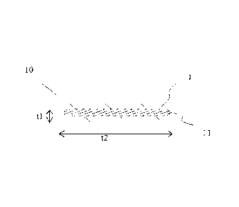
Figs. la-lm present diagrams representing preferred cross-
sections of hoisting ropes, preferably for a passenger ele-
CA 02914023 2015-12-03
14
vator, according to different embodiments of the invention
as seen from the lengthwise direction of the ropes. The
rope (10,20,30,40,50,60, 70,80,90,100,110,120) represented
by Figs. la-11 has a belt-like structure, in other words,
the rope has, as measured in a first direction, which is
perpendicular to the lengthwise direction of the rope,
thickness ti and, as measured in a second direction, which
is perpendicular to the lengthwise direction of the rope
and to the aforesaid first direction, width t2, this width
t2 being substantially larger than the thickness ti. The
width of the rope is thus substantially larger than its
thickness. Moreover, the rope has preferably but not neces-
sarily at least one, preferably two broad and substantially
even surfaces, which broad surface can be efficiently used
as a force-transmitting surface utilizing friction or a
positive contact, because in this way a large contact sur-
face is obtained. The broad surface need not be completely
even, but it may be provided with grooves or protrusions or
it may have a curved shape. The rope preferably has a sub-
stantially uniform structure throughout its length, but not
necessarily, because, if desirable, the cross-section can
be arranged to be cyclically changing e.g. as a cogged
structure. The rope
(10,20,30,40,50,60,70,80,
90,100,110,120) comprises a load-bearing part (11, 21, 31,
41, 51, 61, 71, 81, 91, 101, 111, 121), which is made of a
non-metallic fiber composite comprising carbon fibers or
glass fibers, preferably carbon fibers, in a polymer ma-
trix. The load-bearing part (or possibly load-bearing
parts) and its fibers are oriented in the lengthwise direc-
tion of the rope, which is why the rope retains its struc-
ture at bending. Individual fibers are thus substantially
oriented in the longitudinal direction of the rope. The fi-
bers are thus oriented in the direction of the force when a
tensile force is acting on the rope. The aforesaid rein-
forcing fibers are bound together by the aforesaid polymer
matrix to form an integral load-bearing part. Thus, said
load-bearing part (11, 21, 31, 41, 51, 61, 71, 81, 91, 101,
CA 02914023 2015-12-03
111, 121) is a unitary coherent elongated bar-shaped body.
Said reinforcing fibers are long continuous fibers prefera-
bly oriented in the lengthwise direction of the rope and
preferably extending throughout the length of the rope.
5 Preferably as many of the fibers, most preferably substan-
tially all of the reinforcing fibers of said load-bearing
part are oriented in the lengthwise direction of the rope.
In other words, preferably the reinforcing fibers are sub-
stantially mutually non-entangled. Thus, a load-bearing
10 part is achieved whose cross-sectional structure continues
as unchanged as possible throughout the entire length of
the rope. Said reinforcing fibers are distributed as evenly
as possible in the load-bearing part to ensure that the
load-bearing part is as homogeneous as possible in the
15 transverse direction of the rope. The bending direction of
the ropes shown in figures la-lm would be up or down in the
figures.
The rope 10 presented in Fig. la comprises a load-bearing
composite part 11 having a rectangular shape in cross-
section and surrounded by a polymer layer 1. Alternatively,
the rope can be formed without a polymer layer 1.
The rope 20 presented in Fig. lb comprises two load-bearing
composite parts 21 of rectangular cross-section placed side
by side and surrounded by a polymer layer 1. The polymer
layer 1 comprises a protrusion 22 for guiding the rope, lo-
cated halfway between the edges of a broad side of the rope
10, at the middle of the area between the parts 21. The
rope may also have more than two composite parts placed
side by side in this manner, as illustrated in Fig. lc.
The rope 40 presented in Fig. id comprises a number of
load-bearing composite parts 41 of rectangular cross-
sectional shape placed side by side in the widthwise direc-
tion of the belt and surrounded by a polymer layer 1. The
load-bearing parts shown in the figure are somewhat larger
CA 02914023 2015-12-03
16
in width than in thickness. Alternatively, they could be
implemented as having a substantially square cross-
sectional shape.
The rope 50 presented in Fig. le comprises a load-bearing
composite part 51 of rectangular cross-sectional shape,
with a wire 52 placed on either side of it, the composite
part 51 and the wire 52 being surrounded by a polymer layer
1. The wire 52 may be a rope or strand and is preferably
made of shear-resistant material, such as metal. The wire
is preferably at the same distance from the rope surface as
the composite part 51 and preferably, but not necessarily
spaced apart from the composite part. However, the protec-
tive metallic part could also be in a different form, e.g.
a metallic lath or grid which runs alongside the length of
the composite part.
The rope 60 presented in Fig. lf comprises a load-bearing
composite part 61 of rectangular cross-sectional shape sur-
rounded by a polymer layer 1. Formed on a surface of the
rope 60 is a wedging surface consisting of a plurality of
wedge-shaped protrusions 62, which preferably form a con-
tinuous part of the polymer layer 1.
The rope 70 presented in Fig. lg comprises a load-bearing
composite part 71 of rectangular cross-sectional shape sur-
rounded by a polymer layer 1. The edges of the rope com-
prise swelled portions 72, which preferably form part of
the polymer layer 1. The swelled portions provide the ad-
vantage of guarding the edges of the composite part e.g.
against fraying.
The rope 80 presented in Fig. lh comprises a number of
load-bearing composite parts 81 of round cross-section sur-
rounded by a polymer layer 1.
CA 02914023 2015-12-03
17
The rope 90 presented in Fig. li comprises two load-bearing
parts 91 of square cross-section placed side by side and
surrounded by a polymer layer 1. The polymer layer 1 com-
prises a groove 92 in the region between parts 91 to render
the rope more pliable, so that the rope will readily con-
form e.g. to curved surfaces. Alternatively, the grooves
can be used to guide the rope. The rope may also have more
than two composite parts placed side by side in this manner
as illustrated in Fig. 1j.
The rope 110 presented in Fig. lk comprises a load-bearing
composite part 111 having a substantially rectangular
cross-sectional shape. The width of the load-bearing part
111 is larger than its thickness in a transverse direction
of the rope. The rope 110 has been formed without at all
using a polymer layer like that described in the preceding
embodiments, so the load-bearing part 111 covers the entire
cross-section of the rope.
The rope 120 presented in Fig. 11 comprises a load-bearing
composite part 121 of substantially rectangular cross-
sectional shape having rounded corners. The load-bearing
part 121 has a width larger than its thickness in a trans-
verse direction of the rope and is covered by a thin poly-
mer layer 1. The load-bearing part 121 covers a main pro-
portion of the cross-section of the rope 120. The polymer
layer 1 is very thin as compared to the thickness of the
load-bearing part in the thickness-wise direction ti of the
rope.
The rope 130 presented in Fig. lm comprises mutually adja-
cent load-bearing composite parts 131 of substantially rec-
tangular cross-sectional shape having rounded corners. The
load-bearing part 131 has a width larger than its thickness
in a transverse direction of the rope and is covered by a
thin polymer layer 1. The load-bearing part 131 covers a
main proportion of the cross-section of the rope 130. The
CA 02914023 2015-12-03
18
polymer layer 1 is very thin as compared to the thickness
of the load-bearing part in the thickness-wise direction ti
of the rope. The polymer layer 1 is preferably less than
1.5 mm in thickness, most preferably about 1 mm.
Each one of the above-described ropes comprises at least
one integral load-bearing composite part (11, 21, 31, 41,
51, 61, 71, 81, 91, 101, 111, 121) containing synthetic re-
inforcing fibers embedded in a polymer matrix. The rein-
forcing fibers are most preferably continuous fibers. They
are oriented substantially in the lengthwise direction of
the rope, so that a tensile stress is automatically applied
to the fibers in their lengthwise direction. The matrix
surrounding the reinforcing fibers keeps the fibers in sub-
stantially unchanging positions relative to each other. Be-
ing slightly elastic, the matrix serves as a means of
equalizing the distribution of the force applied to the fi-
bers and reduces inter-fiber contacts and internal wear of
the rope, thus increasing the service life of the rope.
Eventual longitudinal inter-fiber motion consists in elas-
tic shear exerted on the matrix, but the main effect occur-
ring at bending consists in stretching of all materials of
the composite part and not in relative motion between them.
The reinforcing fibers most preferably consist of carbon
fiber, permitting characteristics such as good tensile
stiffness, low-weight structure and good thermal properties
to be achieved. Alternatively, a reinforcement suited for
some uses is glass fiber reinforcement, which provides in-
ter alia a better electric insulation. In this case, the
rope has a somewhat lower tensile stiffness, so it is pos-
sible to use small-diameter drive sheaves. The composite
matrix, in which individual fibers are distributed as homo-
geneously as possible, most preferably consists of epoxy,
which has a good adhesion to reinforcements and a good
strength and behaves advantageously in combination with
glass and carbon fiber. Alternatively, it is possible to
use e.g. polyester or vinyl ester. Most preferably the corn-
CA 02914023 2015-12-03
19
posite part (10,20,30,40,50,60,70,80,90, 100,110,120) com-
prises about 60% carbon fiber and 40% epoxy. As stated
above, the rope may comprise a polymer layer 1. The polymer
layer 1 preferably consists of elastomer, most preferably
high-friction elastomer, such as e.g. polyurethane, so that
the friction between the drive sheave and the rope will be
sufficient for moving the rope.
The table below shows the advantageous properties of carbon
fiber and glass fiber. They have good strength and stiff-
ness properties while also having a good thermal re-
sistance, which is important in elevators, because a poor
thermal resistance may result in damage to the hoisting
ropes or even in the ropes catching fire, which is a safety
hazard. A good thermal conductivity contributes inter alia
to the transmission of frictional heat, thereby reducing
excessive heating of the drive sheave or accumulation of
heat in the rope elements.
GassfiberCarbonfiber Aramid fiber
Density kg/m3 2540 1820 1450
Strength N/mm2 3600 4500 3620
Stiffness N/mm2 75000 200000-600000 75000..A20000
450...500, carboniz-
SofteningtumdeWC 850 >2000 ing
Thermal conductivity VNUmK 0.8 105 0.05
Fig. 2 represents an elevator according to an embodiment of
the invention in which a belt-like rope is utilized. The
ropes A and B are preferably, but not necessarily, imple-
mented according to one of Figs. la-11. A number of belt-
like ropes A and B passing around the drive sheave 2 are
set one over the other against each other. The ropes A and
B are of belt-like design and rope A is set against the
drive sheave 2 and rope B is set against rope A, so that
CA 02914023 2015-12-03
the thickness of each belt-like rope A and B in the direc-
tion of the center axis of the drive sheave 2 is larger
than in the radial direction of the drive sheave 2. The
ropes A and B moving at different radii have different
5 speeds. The ropes A and B passing around a diverting pul-
ley 4 mounted on the elevator car or counterweight 3 are
connected together by a chain 5, which compensates the
speed difference between the ropes A and B moving at dif-
ferent speeds. The chain is passed around a freely rotating
10 diverting pulley 4, so that, if necessary, the rope can
move around the diverting pulley at a speed corresponding
to the speed difference between the ropes A and B placed
against the drive sheave. This compensation can also be im-
plemented in other ways than by using a chain. Instead of a
15 chain, it is possible to use e.g. a belt or rope. Alterna-
tively, it is possible to omit the chain 5 and implement
rope A and rope B depicted in the figure as a single con-
tinuous rope, which can be passed around the diverting pul-
ley 4 and back up, so that a portion of the rope leans
20 against another portion of the same rope leaning against
the drive sheave. Ropes set one over the other can also be
placed side by side on the drive sheave as illustrated in
Fig. 3, thus allowing efficient space utilization. In addi-
tion, it is also possible to pass around the drive sheave
more than two ropes one over the other.
Fig. 3 presents a detail of the elevator according to Fig.
2, depicted in the direction of section A-A. Supported on
the drive sheave are a number of mutually superimposed
ropes A and B disposed mutually adjacently, each set of
said mutually superimposed ropes comprising a number of
belt-like ropes A and B. In the figure, the mutually super-
imposed ropes are separated from the adjacent mutually su-
perimposed ropes by a protrusion u provided on the surface
of the drive sheave, said protrusion u preferably protrud-
ing from the surface of the drive sheave along the whole
length of the circumference, so that the protrusion u
CA 02914023 2015-12-03
21
guides the ropes. The mutually parallel protrusions u on
the drive sheave 2 thus form between them groove-shaped
guide surfaces for the ropes A and B. The protrusions u
preferably have a height reaching at least up to the level
of the midline of the material thickness of the last one B
of the mutually superimposed ropes as seen in sequence
starting from the surface of the drive sheave 2. If desira-
ble, it is naturally also possible to implement the drive
sheave in Fig. 3 without protrusions or with protrusions
shaped differently. Of course, if desirable, the elevator
described can also be implemented in such manner that there
are no mutually adjacent ropes but only mutually superim-
posed ropes A,B on the drive sheave. Disposing the ropes in
a mutually superimposed manner enables a compact construc-
tion and permits the use of a drive sheave having a shorter
dimension as measured in the axial direction.
Fig. 4 represents the rope system of an elevator according
to an embodiment of the invention, wherein the rope 8 has
been arranged using a layout of reverse bending type, i.e.
a layout where the bending direction varies as the rope is
moving from pulley 2 to pulley 7 and further to pulley 9.
In this case, the rope span d is freely adjustable, because
the variation in bending direction is not detrimental when
a rope according to the invention is used, for the rope is
non-braided, retains its structure at bending and is thin
in the bending direction. At the same time, the distance
through which the rope remains in contact with the drive
sheave may be over 180 degrees, which is advantageous in
respect of friction. The figure only shows a view of the
roping in the region of the diverting pulleys. From pulleys
2 and 9, the rope 8 may be passed according to a known
technology to the elevator car and/or counterweight and/or
to an anchorage in the elevator shaft. This may be imple-
mented e.g. in such manner that the rope continues from
pulley 2 functioning as a drive sheave to the elevator car
and from pulley 9 to the counterweight, or the other way
CA 02914023 2015-12-03
22
round. In construction, the rope 8 is preferably one of
those presented in Figs. la-11.
Fig. 5 is a diagrammatic representation of an embodiment of
the elevator of the invention provided with a condition
monitoring arrangement for monitoring the condition of the
rope 213, particularly for monitoring the condition of the
polymer coating surrounding the load-bearing part. The rope
is preferably of a type as illustrated above in one of
Figs. la-11 and comprises an electrically conductive part,
preferably a part containing carbon fiber. The condition
monitoring arrangement comprises a condition monitoring de-
vice 210 connected to the end of the rope 213, to the load-
bearing part of the rope 213 at a point near its anchorage
216, said part being electrically conductive. The arrange-
ment further comprises a conductor 212 connected to an
electrically conductive, preferably metallic diverting pul-
ley 211 guiding the rope 213 and also to the condition mon-
itoring device 210. The condition monitoring device 210
connects conductors 212 and 214 and has been arranged to
produce a voltage between the conductors. As the electri-
cally insulating polymer coating is wearing off, its insu-
lating capacity is reduced. Finally, the electrically con-
ductive parts inside the rope come into contact with the
pulley 211, the circuit between the conductors 214 and 212
being thus closed. The condition monitoring device 210 fur-
ther comprises means for observing an electric property of
the circuit formed by the conductors 212 and 214, the rope
213 and the pulley 211. These means may comprise e.g. a
sensor and a processor, which, upon detecting a change in
the electric property, activate an alarm about excessive
rope wear. The electric property to be observed may be e.g.
a change in the electric current flowing through the afore-
said circuit or in the resistance, or a change in the mag-
netic field or voltage.
CA 02914023 2015-12-03
23
Fig. 6 is a diagrammatic representation of an embodiment of
the elevator of the invention provided with a condition
monitoring arrangement for monitoring the condition of the
rope 219, particularly for monitoring the condition of the
load-bearing part. The rope 219 is preferably of one of the
types described above and comprises at least one electri-
cally conductive part 217, 218, 220, 221, preferably a part
containing carbon fiber. The condition monitoring arrange-
ment comprises a condition monitoring device 210 connected
to the electrically conductive part of the rope, which
preferably is a load-bearing part. The condition monitoring
device 210 comprises means, such as e.g. a voltage or cur-
rent source for transmitting an excitation signal into the
load-bearing part of the rope 219 and means for detecting,
from another point of the load-bearing part or from a part
connected to it, a response signal responding to the trans-
mitted signal. On the basis of the response signal, prefer-
ably by comparing it to predetermined limit values by means
of a processor, the condition monitoring device has been
arranged to infer the condition of the load-bearing part in
the area between the point of input of the excitation sig-
nal and the point of measurement of the response signal.
The condition monitoring device has been arranged to acti-
vate an alarm if the response signal does not fall within a
desired range of values. The response signal changes when a
change occurs in an electric property dependent on the con-
dition of the load-bearing part of the rope, such as re-
sistance or capacitance. For example, resistance increasing
due to cracks will produce a change in the response signal,
from which change it can be deduced that the load-bearing
part is in a weak condition. Preferably this is arranged as
illustrated in Fig. 6 by having the condition monitoring
device 210 placed at a first end of the rope 219 and con-
nected to two load-bearing parts 217 and 218, which are
connected at the second end of the rope 219 by conductors
222. With this arrangement, the condition of both parts
217, 218 can be monitored simultaneously. When there are
CA 02914023 2015-12-03
24
several objects to be monitored, the disturbance caused by
mutually adjacent load-bearing parts to each other can be
reduced by interconnecting non-adjacent load-bearing parts
with conductors 222, preferably connecting every second
part to each other and to the condition monitoring device
210.
Fig. 7 presents an embodiment of the elevator of the inven-
tion wherein the elevator rope system comprises one or more
ropes 10,20,30,40,50,60,70,80,90,100,110,120. The first end
of the rope 10,20,30,40,50,60,70,80,90,100,110,120,8 is se-
cured to the elevator car 3 and the second end to the coun-
terweight 6. The rope is moved by means of a drive sheave 2
supported on the building, the drive sheave being connected
to a power source, such as e.g. an electric motor (not
shown), imparting rotation to the drive sheave. The rope is
preferably of a construction as illustrated in one of Figs.
la-11. The elevator is preferably a passenger elevator,
which has been installed to travel in an elevator shaft S
in the building. The elevator presented in Fig. 7 can be
utilized with certain modifications for different hoisting
heights.
An advantageous hoisting height range for the elevator pre-
sented in Fig. 7 is over 100 meters, preferably over 150
meters, and still more preferably over 250 meters. In ele-
vators of this order of hoisting heights, the rope masses
already have a very great importance regarding energy effi-
ciency and structures of the elevator. Consequently, the
use of a rope according to the invention for moving the el-
evator car 3 of a high-rise elevator is particularly advan-
tageous, because in elevators designed for large hoisting
heights the rope masses have a particularly great effect.
Thus, it is possible to achieve, inter alia, a high-rise
elevator having a reduced energy consumption. When the
hoisting height range for the elevator in Fig. 7 is over
CA 02914023 2015-12-03
100 meters, it is preferable, but not strictly necessary,
to provide the elevator with a compensating rope.
The ropes described are also well applicable for use in
5 counterweighted elevators, e.g. passenger elevators in res-
idential buildings, that have a hoisting height of over 30
m. In the case of such hoisting heights, compensating ropes
have traditionally been necessary. The present invention
allows the mass of compensating ropes to be reduced or even
10 eliminated altogether. In this respect, the ropes described
here are even better applicable for use in elevators having
a hoisting height of 30-80 meters, because in these eleva-
tors the need for a compensating rope can even be eliminat-
ed altogether. However, the hoisting height is most prefer-
15 ably over 40 m, because in the case of such heights the
need for a compensating rope is most critical, and below 80
m, in which height range, by using low-weight ropes, the
elevator can, if desirable, still be implemented even with-
out using compensating ropes at all. Fig. 7 depicts only
20 one rope, but preferably the counterweight and elevator car
are connected together by a number of ropes.
In the present application, 'load-bearing part' refers to a
rope element that carries a significant proportion of the
25 load imposed on the rope in its longitudinal direction,
e.g. of the load imposed on the rope by an elevator car
and/or counterweight supported by the rope. The load pro-
duces in the load-bearing part a tension in the longitudi-
nal direction of the rope, which tension is transmitted
further in the longitudinal direction of the rope inside
the load-bearing part in question. Thus, the load-bearing
part can e.g. transmit the longitudinal force imposed on
the rope by the drive sheave to the counterweight and/or
elevator car in order to move them. For example in Fig. 7,
where the counterweight 6 and elevator car 3 are supported
by the rope (10,20,30,40,50,60,70,80,90,100,110,120), more
precisely speaking by the load-bearing part in the rope,
CA 02914023 2015-12-03
26
which load-bearing part extends from the elevator car 3 to
the counterweight 6. The rope (20,30,40,50,60,70,80,90,100,
110,120) is secured to the counterweight and to the eleva-
tor car. The tension produced by the weight of the counter-
weight/elevator car is transmitted from the securing point
via the load-bearing part of the rope (10,20,30,
40,50,60,70,80,90,100,110,120) upwards from the counter-
weight/elevator car at least up to the drive sheave 2.
As mentioned above, the reinforcing fibers of the load-
bearing part in the rope (10,20,30,40,50,60,70,80,90,100,
110,120,130,8,A,B) of the invention for a hoisting device,
especially a rope for a passenger elevator, are preferably
continuous fibers. Thus the fibers are preferably long fi-
bers, most preferably extending throughout the entire
length of the rope. Therefore, the rope can be produced by
coiling the reinforcing fibers from a continuous fiber tow,
into which a polymer matrix is absorbed. Substantially all
of the reinforcing fibers of the load-bearing part
(11,21,31,41,51, 61,71,81,91,101,121) are preferably made
of one and the same material.
As explained above, the reinforcing fibers in the load-
bearing part (11, 21, 31, 41, 51, 61, 71, 81, 91, 101, 111,
121) are contained in a polymer matrix. This means that, in
the invention, individual reinforcing fibers are bound to-
gether by a polymer matrix, e.g. by immersing them during
manufacture into polymer matrix material. Therefore, indi-
vidual reinforcing fibers bound together by the polymer ma-
trix have between them some polymer of the matrix. In the
invention, a large quantity of reinforcing fibers bound to-
gether and extending in the longitudinal direction of the
rope are distributed in the polymer matrix. The reinforcing
fibers are preferably distributed substantially uniformly,
i.e. homogeneously in the polymer matrix, so that the load-
bearing part is as homogeneous as possible as observed in
the direction of the cross-section of the rope. In other
CA 02914023 2015-12-03
27
words, the fiber density in the cross-section of the load-
bearing part thus does not vary greatly. The reinforcing
fibers together with the matrix constitute a load-bearing
part, inside which no chafing relative motion takes place
when the rope is being bent. In the invention, individual
reinforcing fibers in the load-bearing part (11, 21, 31,
41, 51, 61, 71, 81, 91, 101, 111, 121,131) are mainly sur-
rounded by the polymer matrix, but fiber-fiber contacts may
occur here and there because it is difficult to control the
positions of individual fibers relative to each other dur-
ing their simultaneous impregnation with polymer matrix,
and, on the other hand, complete elimination of incidental
fiber-fiber contacts is not an absolute necessity regarding
the functionality of the invention. However, if their inci-
dental occurrences are to be reduced, then it is possible
to pre-coat individual reinforcing fibers so that they al-
ready have a polymer coating around them before the indi-
vidual reinforcing fibers are bound together.
In the invention, individual reinforcing fibers of the
load-bearing part (11, 21, 31, 41, 51, 61, 71, 81, 91, 101,
111, 121, 131) comprise polymer matrix material around
them. The polymer matrix is thus placed immediately against
the reinforcing fiber, although between them there may be a
thin coating on the reinforcing fiber, e.g. a primer ar-
ranged on the surface of the reinforcing fiber during pro-
duction to improve chemical adhesion to the matrix materi-
al. Individual reinforcing fibers are uniformly distributed
in the load-bearing part (11, 21, 31, 41, 51, 61, 71, 81,
91, 101, 111, 121, 131) so that individual reinforcing fi-
bers have some matrix polymer between them. Preferably most
of the spaces between individual reinforcing fibers in the
load-bearing part are filled with matrix polymer. Most
preferably substantially all of the spaces between individ-
ual reinforcing fibers in the load-bearing part are filled
with matrix polymer. In the inter-fiber areas there may ap-
CA 02914023 2015-12-03
28
pear pores, but it is preferable to minimize the number of
these.
The matrix of the load-bearing part (11, 21, 31, 41, 51,
61, 71, 81, 91, 101, 111, 121, 131) most preferably has
hard material properties. A hard matrix helps support the
reinforcing fibers especially when the rope is being bent.
At bending, the reinforcing fibers closest to the outer
surface of the bent rope are subjected to tension whereas
the carbon fibers closest to the inner surface are subject-
ed to compression in their lengthwise direction. Compres-
sion tends to cause the reinforcing fibers to buckle. By
selecting a hard material for the polymer matrix, it is
possible to prevent buckling of fibers, because a hard ma-
terial can provide support for the fibers and thus prevent
them from buckling and equalize tensions within the rope.
Thus it is preferable, inter alia to permit reduction of
the bending radius of the rope, to use a polymer matrix
consisting of a polymer that is hard, preferably other than
elastomer (an example of elastomer: rubber) or similar
elastically behaving or yielding material. The most prefer-
able materials are epoxy, polyester, phenolic plastic or
vinyl ester. The polymer matrix is preferably so hard that
its coefficient of elasticity (E) is over 2 GPa, most pref-
erably over 2.5 GPa. In this case, the coefficient of elas-
ticity is preferably in the range of 2.5-10 GPa, most pref-
erably in the range of 2.5-3.5 GPa.
Fig. 8 presents within a circle a partial cross-section of
the surface structure of the load-bearing part (as seen in
the lengthwise direction of the rope), this cross-section
showing the manner in which the reinforcing fibers in the
load-bearing parts (11, 21, 31, 41, 51, 61, 71, 81, 91,
101, 111, 121, 131) described elsewhere in the application
are preferably arranged in the polymer matrix. The figure
shows how the reinforcing fibers F are distributed substan-
tially uniformly in the polymer matrix M, which surrounds
CA 02914023 2015-12-03
29
the fibers and adheres to the fibers. The polymer matrix M
fills the spaces between reinforcing fibers F and, consist-
ing of coherent solid material, binds substantially all re-
inforcing fibers F in the matrix together. This prevents
mutual chafing between reinforcing fibers F and chafing be-
tween matrix M and reinforcing fibers F. Between individual
reinforcing fibers, preferably all the reinforcing fibers F
and the matrix M there is a chemical bond, which provides
the advantage of structural coherence, among other things.
To strengthen the chemical bond, it is possible, but not
necessary, to provide a coating (not shown) between the re-
inforcing fibers and the polymer matrix M. The polymer ma-
trix M is as described elsewhere in the application and may
comprise, besides a basic polymer, additives for fine ad-
justment of the matrix properties. The polymer matrix M
preferably consists of a hard elastomer.
In the use according to the invention, a rope as described
in connection with one of Figs. la-lm is used as the hoist-
ing rope of an elevator, particularly a passenger elevator.
One of the advantages achieved is an improved energy effi-
ciency of the elevator. In the use according to the inven-
tion, at least one rope, but preferably a number of ropes
of a construction such that the width of the rope is larger
than its thickness in a transverse direction of the rope
are fitted to support and move an elevator car, said rope
comprising a load-bearing part (11, 21, 31, 41, 51, 61, 71,
81, 91, 101, 111, 121, 131) made of a composite material,
which composite material comprises reinforcing fibers,
which consist of carbon fiber or glass fiber, in a polymer
matrix. The hoisting rope is most preferably secured by one
end to the elevator car and by the other end to a counter-
weight in the manner described in connection with Fig. 7,
but it is applicable for use in elevators without counter-
weight as well. Although the figures only show elevators
with a 1:1 hoisting ratio, the rope described is also ap-
plicable for use as a hoisting rope in an elevator with a
CA 02914023 2015-12-03
1:2 hoisting ratio. The rope (10,20,30,40,50,60,70,80,90,
100,110, 120,130,8,A,B) is particularly well suited for use
as a hoisting rope in an elevator having a large hoisting
height, preferably an elevator having a hoisting height of
5 over 100 meters. The rope defined can also be used to im-
plement a new elevator without a compensating rope, or to
convert an old elevator into one without a compensating
rope. The proposed rope (10,20,30,40,50,60,70,80,90,100,
110,120,130,8,A,B) is well applicable for use in an eleva-
10 tor having a hoisting height of over 30 meters, preferably
30-80 meters, most preferably 40-80 meters, and implemented
without a compensating rope. 'Implemented without a compen-
sating rope' means that the counterweight and elevator car
are not connected by a compensating rope. Still, even
15 though there is no such specific compensating rope, it is
possible that a car cable attached to the elevator car and
especially arranged to be hanging between the elevator
shaft and elevator car may participate in the compensation
of the imbalance of the car rope masses. In the case of an
20 elevator without a compensating rope, it is advantageous to
provide the counterweight with means arranged to engage the
counterweight guide rails in a counterweight bounce situa-
tion, which bounce situation can be detected by bounce mon-
itoring means, e.g. from a decrease in the tension of the
25 rope supporting the counterweight.
It is obvious that the cross-sections described in the pre-
sent application can also be utilized in ropes in which the
composite has been replaced with some other material, such
30 as e.g. metal. It is likewise obvious that a rope compris-
ing a straight composite load-bearing part may have some
other cross-sectional shape than those described, e.g. a
round or oval shape.
The advantages of the invention will be the more pro-
nounced, the greater the hoisting height of the elevator.
By utilizing ropes according to the invention, it is possi-
CA 02914023 2015-12-03
31
ble to achieve a mega-high-rise elevator having a hoisting
height even as large as about 500 meters. Implementing
hoisting heights of this order with prior-art ropes has
been practically impossible or at least economically unrea-
sonable. For example, if prior-art ropes in which the load-
bearing part comprises metal braidings were used, the
hoisting ropes would weigh up to tens of thousands of kilo-
grams. Consequently, the mass of the hoisting ropes would
be considerably greater than the payload.
The invention has been described in the application from
different points of view. Although substantially the same
invention can be defined in different ways, entities de-
fined by definitions starting from different points of view
may slightly differ from each other and thus constitute
separate inventions independently of each other.
It is obvious to a person skilled in the art that
the invention is not exclusively limited to the embodiments
described above, in which the invention has been described
by way of example, but that many variations and different
embodiments of the invention are possible within the scope
of the inventive concept defined in the claims presented
below. Thus it is obvious that the ropes described may be
provided with a cogged surface or some other type of pat-
terned surface to produce a positive contact with the drive
sheave. It is also obvious that the rectangular composite
parts presented in Figs. la-11 may comprise edges more
starkly rounded than those illustrated or edges not rounded
at all. Similarly, the polymer layer 1 of the ropes may
comprise edges/corners more starkly rounded than those il-
lustrated or edges/corners not rounded at all. It is like-
wise obvious that the load-bearing
part/parts
(11,21,31,41,51,61,71,81,91) in the embodiments in Figs.
la-lj can be arranged to cover most of the cross-section of
the rope. In this case, the sheath-like polymer layer 1
surrounding the load-bearing part/parts is made thinner as
CA 02914023 2015-12-03
32
compared to the thickness of the load-bearing part in the
thickness-wise direction ti of the rope. It is likewise ob-
vious that, in conjunction with the solutions represented
by Figs. 2, 3 and 4, it is possible to use belts of other
types than those presented. It is likewise obvious that
both carbon fiber and glass fiber can be used in the same
composite part if necessary. It is likewise obvious that
the thickness of the polymer layer may be different from
that described. It is likewise obvious that the shear-
resistant part could be used as an additional component
with any other rope structure showed in this application.
It is likewise obvious that the matrix polymer in which the
reinforcing fibers are distributed may comprise - mixed in
the basic matrix polymer, such as e.g. epoxy - auxiliary
materials, such as e.g. reinforcements, fillers, colors,
fire retardants, stabilizers or corresponding agents. It is
likewise obvious that, although the polymer matrix prefera-
bly does not consist of elastomer, the invention can also
be utilized using an elastomer matrix. It is also obvious
that the fibers need not necessarily be round in cross-
section, but they may have some other cross-sectional
shape. It is further obvious that auxiliary materials, such
as e.g. reinforcements, fillers, colors, fire retardants,
stabilizers or corresponding agents, may be mixed in the
basic polymer of the layer 1, e.g. in polyurethane. It is
likewise obvious that the invention can also be applied in
elevators designed for hoisting heights other than those
considered above.