Note : Les descriptions sont présentées dans la langue officielle dans laquelle elles ont été soumises.
CA 02914903 2015-12-09
WO 2015/002633 PCT/US2013/048932
METHOD FOR OUTLET DEVICE TO PROTECT UPSTREAM PARALLEL ARC
FAULT
TECHNICAL FIELD
[0001] The present disclosure relates generally to fault detection in an
electrical system
and more specifically to upstream arc fault protection through a switching
element at an
outlet.
BACKGROUND
[0002] Traditional circuit breakers detect overcurrent conditions from
electrical outlets
downstream from the circuit breaker. Such breakers trip on detection of an
overcurrent
situation occurring from loads plugged into one of the downstream outlets.
There are
additional hazards including ground faults from a line conductor or a neutral
conductor.
Ground faults require ground fault circuit interrupter devices to detect and
interrupt power to
outlets. Another form of fault is an arc fault that may occur on the neutral
and/or conductor
lines between the outlets and the circuit breaker. Protection against arc
faults is increasingly
required in residential settings in the form of arc fault circuit interrupter
(AFCI) devices.
Such devices detect arcs in neutral and/or line conductors and remove power
before such arcs
can cause an electrical fire. AFCI protection may be located in outlets. Such
outlets monitor
and protect against faults with a set of contacts downstream of a detection
module such as at
the outlet itself. Faults are typically detected by the detection sensor in
the outlet or outlets
downstream of a conventional thermal-magnetic circuit breaker which breaks a
contact in the
AFCI outlet and thereby prevents current flow through the outlet and outlets
downstream
from the AFCI protected outlet.
[0003] With present devices for fault detection, the interruption by the
AFCI outlet may
only be triggered as a result of parallel arc faults detected downstream from
the outlet or
series arc faults. Thus, the outlet and corresponding detector cannot
interrupt an upstream
parallel arc fault (occurring between the outlet and the circuit breaker)
because the contact
interruption device at a known AFCI outlet cannot detect such faults and even
if the contact
interruption mechanism is triggered, the current would continue to flow
through the fault. In
a conventional electrical system, conventional circuit breakers cannot react
quickly enough to
such arc faults between the circuit breaker and an outlet. This poses a
potential danger since
1
CA 02914903 2015-12-09
WO 2015/002633 PCT/US2013/048932
the arc fault may be allowed to continue for some time before the circuit
breaker interrupts
power to the outlet.
[0004] Thus, a need exists for an arc fault detection and interruption
system that detects
parallel arc faults at points upstream from an outlet. There is a further need
for an
interruption system that interrupts power by tripping a circuit breaker
mechanism upstream of
the outlet. There is a further need for an arc fault detection system that
uses existing
components in an AFCI outlet for detection of arc faults upstream of an
outlet.
SUMMARY
[0005] One disclosed example is an arc fault circuit interrupter (AFCI)
outlet which
detects and interrupts upstream parallel arc faults in conjunction with a
conventional thermal-
magnetic circuit breaker. The example AFCI outlet includes a switching element
coupled
between the line and neutral conductors, a voltage sensor coupled between the
neutral and
line conductors and a current sensor on the line conductor. When a parallel
upstream arc
fault is detected by sensing a large voltage drop but no current, the
switching element is
closed and current flows through the relatively lower resistance switching
element
interrupting power through the arc fault. The closed switching element results
in an
overcurrent condition causing the upstream conventional thermal-magnetic
circuit breaker to
trip.
[0006] Thus, the provided AFCI outlet allows detection of parallel arc
faults upstream
which currently cannot be protected by known AFCI outlets. The example outlet
does not
require additional sensor components from known AFCI outlets but provides an
interruption
at the proximate location of the detected parallel arc fault. Interruption of
the upstream
parallel fault occurs at the branch circuit breaker. The example AFCI outlet
speeds up the
branch circuit breaker response time by increasing the current level into the
over current
protection level of the branch circuit breaker. The example outlet causes
hazardous arcing
current to transition to strictly over current fault current, thus reducing
the risk of fire. The
arrangement also allows reset capability for unwanted tripping due to series
arc fault
detection to be placed in position closer to the user (i.e., in the AFCI
outlet) and without the
need for a trip signal communication to an electronic upstream circuit
breaker. Further, the
switching element system, upon detection of a parallel arc fault upstream of
the AFCI outlet,
produces a short which ensures that the resultant current always exceeds the
over current trip
2
level of the branch circuit breaker and thus removes the practical limitation
on the length of
the wire connecting the AFCI outlet to the circuit breaker (the "home run")
for effective
parallel fault interruption.
[0006a] According to a first aspect, an outlet to perform arc fault protection
and detection is
provided, the outlet being located downstream from a circuit breaker. The
outlet comprises a
switching element coupled between a line conductor and a neutral conductor
having an open
position and a closed position coupling the line conductor to the neutral
conductor; a voltage
sensor coupled between the line conductor and the neutral conductor; a current
sensor
coupled on the line conductor; and a controller coupled to the switching
element, the current
sensor and the voltage sensor, the controller detecting a large voltage drop
on the line
conductor and no corresponding substantial increase in current on the line
conductor
indicative of a parallel arc fault between the outlet and the circuit breaker,
and the controller
closing the switching element in response to the detecting, wherein the closed
position of the
switching element creates a low resistance path for current flow sufficient to
cause the circuit
breaker to trip.
[0006b] According to a second aspect, a method of determining a parallel arc
fault upstream
of an outlet coupled to a circuit breaker via a line conductor and a neutral
conductor is
provided. The method comprises detecting a high voltage drop between the line
conductor
and neutral conductor via a voltage sensor coupled between the line conductor
and neutral
conductor in the outlet; detecting no substantial corresponding increase in
current via a
current detector on the line conductor at the outlet; and closing a switching
element coupled
between the line conductor and the neutral conductor to create a low
resistance current path
between the line conductor and neutral conductor when the high voltage drop
and no
substantial increase in current is detected, wherein the closed position of
the switching
element creates a low resistance path for current flow sufficient to cause the
circuit breaker to
trip.
[0006c] According to a third aspect, a system to interrupt power when an
upstream parallel
arc fault is detected is provided. The system comprises a line conductor; a
neutral conductor;
a circuit breaker coupled to the line conductor and the neutral conductor, the
circuit breaker
3
CA 2914903 2019-09-23
interrupting the flow of power when an overcurrent condition is detected; an
arc fault
protection outlet coupled to the circuit breaker via the neutral and line
conductors, the outlet
including a switching element coupled between the neutral and line conductors,
an outlet
connector for connection to a load, a controller coupled to the switching
element to control
the switching element, a voltage sensor coupled between the neutral and line
conductors and
a current sensor coupled to the line conductor, the controller closing the
switching element to
electrically couple the neutral and line conductors when a high voltage drop
is detected
without an corresponding substantial increase in current thereby indicating
the occurrence of
an arc fault between the outlet and the circuit breaker, wherein closing the
switching element
creates a low resistance path for current flow sufficient to cause the circuit
breaker to trip.
[0007] Additional aspects will be apparent to those of ordinary skill in the
art in view of the
detailed description of various embodiments, which is made with reference to
the drawings, a
brief description of which is provided below.
BRIEF DESCRIPTION OF THE DRAWINGS
[0008] The foregoing and other advantages of the invention will become
apparent upon
reading the following detailed description and upon reference to the drawings.
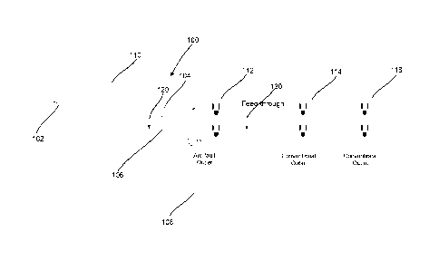
[0009] FIG. 1 is a circuit diagram of a system of outlets with an AFCI
outlet for
upstream arc fault detection and protection with a conventional circuit
breaker;
[0010] FIG. 2 is a detailed circuit diagram of the detection elements
and switching
elements in the AFCI outlet in FIG. 1 that detect and interrupts upstream arc
faults; and
[0011] FIG. 3 is a flow diagram of the control algorithm executed by the
controller at
the outlet in FIG. 2 to detect and protect against arc faults.
[0012] While the invention is susceptible to various modifications and
alternative forms,
specific embodiments have been shown by way of example in the drawings and
will be
described in detail herein. It should be understood, however, that the
invention is not
intended to be limited to the particular forms disclosed. Rather, the
invention is to cover all
modifications, equivalents, and alternatives falling within the spirit and
scope of the invention
as defined by the appended claims.
3a
CA 2914903 2019-09-23
DETAILED DESCRIPTION
[0013] One
disclosed example is an outlet to perform arc fault protection and detection.
The outlet is located downstream from a circuit breaker. The outlet includes a
switching
element coupled between the line conductor and the neutral conductor having an
open
position and a closed position coupling the line conductor to the neutral
conductor. The
outlet includes a voltage sensor coupled between the line conductor and the
neutral conductor
and a current sensor coupled on the line conductor. A controller is coupled to
the switching
element, the current sensor and the voltage sensor. The controller detects a
large voltage
drop on the line conductor and no corresponding substantial increase in
current on the line
3b
CA 2914903 2019-09-23
CA 02914903 2015-12-09
WO 2015/002633 PCMJS2013/048932
conductor indicative of a parallel arc fault between the outlet and the
circuit breaker. The
controller closes the switching element in response to the detecting.
[0014] Another example is a method of determining an arc fault upstream of
an outlet
coupled to a circuit breaker via a line conductor and a neutral conductor. A
high voltage drop
is detected between the line conductor and neutral conductor via a voltage
sensor coupled
between the line conductor and neutral conductor in the outlet. No substantial
corresponding
increase in current via a current detector on the line conductor at the outlet
is detected when
the high voltage is detected. A switching element coupled between the line
conductor and the
neutral conductor is closed to create a low resistance current path between
the line conductor
and neutral conductor when the high voltage and no substantial increase in
current is
detected.
[0015] Another example is a system to interrupt power when a parallel arc
fault is
detected. The system includes a line conductor and a neutral conductor. A
circuit breaker is
coupled to the line conductor and the neutral conductor. The circuit breaker
interrupts the
flow of power when an overcurrent condition is detected. An arc fault
protection outlet is
coupled to the circuit breaker via the neutral and line conductors. The outlet
includes a
switching element coupled between the neutral and line conductors, an outlet
connector for
connection to a load. The outlet includes a controller coupled to the
switching element to
control the switching element. A voltage sensor is coupled between the neutral
and line
conductors and a current sensor is coupled to the line conductor. The
controller closes the
switching element to electrically couple the neutral and line conductors when
a high voltage
drop is detected without an corresponding substantial increase in current
thereby indicating
the occurrence of an arc fault between the outlet and the circuit breaker.
[0016] FIG. 1 shows an electrical supply system 100 which may be used in a
residential
dwelling or other building. The system 100 includes an alternating current
source 102 which
is coupled to a line conductor 104, a neutral conductor 106 and a ground
conductor 108. The
alternating current source 102 is coupled to a circuit breaker 110 via the
line conductor 104
and the neutral conductor 106. The circuit breaker 110 is coupled in series to
an arc fault
protection outlet 112 downstream from the circuit breaker 110 and upstream
from
conventional outlets 114 and 116. The outlets 112, 114 and 116 provide
electrical connection
to the line conductor 104, neutral conductor 106 and ground conductor 108 for
loads plugged
into the outlets 112, 114 and 116 via conventional three pronged male
connectors.
4
CA 02914903 2015-12-09
WO 2015/002633 PCMJS2013/048932
[0017] As will be explained below, the arc fault protection outlet 112
provides arc fault
detection and protection for the outlets 114 and 116 which are located
downstream from the
outlet 112. A parallel arc fault 120 may occur upstream of the arc fault
protection outlet 112
between the line conductor 104 and the neutral conductor 106. Other parallel
arc faults such
as an arc fault 130 may occur downstream of the protection outlet 112.
Conventional arc
fault detection systems in the arc fault protection outlet 112 detect and
protect against parallel
arc faults downstream such as the arc fault 130 but cannot protect against arc
faults upstream
from the arc fault protection outlet 112 such as the parallel arc fault 120
despite the fact that
the arc fault 120 may occur in proximity to the arc fault protection outlet
112.
[0018] FIG. 2 shows a detailed electrical diagram of the components of the
arc fault
protection outlet 112 in FIG. 1. The arc fault protection outlet 112 in this
example is capable
of detecting parallel arc faults on a branch upstream of the outlet 112 and
causing an
interruption of power to prevent fire risk from the arc fault. A faceplate 202
provides
conventional three prong female connectors to load devices that may be
provided power from
the arc fault protection outlet 112. The arc fault protection outlet 112
includes a line
conductor 204 coupled to the line conductor 104 in FIG. 1 and a neutral
conductor 206
coupled to the neutral conductor 106 in FIG. 1. The line conductor 204 and the
neutral
conductor 206 supply power to the faceplate 202. In this example, the
faceplate 202 includes
two conventional three prong connectors 210 and 212. A load with a
conventional three
prong plug may be plugged into the three prong connector 210 or 212. When a
load is
plugged in, power is supplied through the line conductor 204 and the neutral
conductor 206 to
create a closed circuit.
[0019] The outlet 212 includes a switching element 220 which is coupled
between the
line conductor 204 and the neutral conductor 206. In this example, the
switching element
220 is a solid state transistor but other types of switching devices such as
relays, IGBTs,
MOSFETS, etc. may be used. The switching element 220 has a closed position
allowing
electrical connection between the line conductor 204 and the neutral conductor
206. The
switching element 220 also has an open position which creates an open circuit
between the
line conductor 204 and the neutral conductor 206. In normal operation, the
switching
element 220 is in an open position, allowing power to flow through line
conductor 204 to the
connectors 210 and 212.
CA 02914903 2015-12-09
WO 2015/002633 PCMJS2013/048932
[0020] The arc fault protection outlet 112 also includes a controller 222,
a current
sensor 224, a voltage sensor 226 and a contact relay 230. As is understood,
the controller 222
in conjunction with the current sensor 224 and the voltage sensor 226 provide
downstream
arc fault detection and current interruption for the arc fault protection
outlet 212. In the case
of a parallel arc fault occurring downstream from the arc fault protection
outlet 112, a voltage
is detected on the voltage sensor 226 and a change in current is detected on
the current sensor
224. In the case of a series arc fault, a change in current is detected by the
controller 222. In
either case, the controller 222 activates the contact relay 230 and therefore
interrupts the
connection on the line conductor 204 thereby preventing current from flowing
to the three
prong connectors 210 and 212 as well as the three prong connectors on the
outlets 114 and
116 downstream from the arc fault protection outlet 112. The contact relay 230
may typically
be reset by pressing a button (not shown) on the faceplate 202. Such a
conventional arc fault
detection system cannot prevent an upstream parallel arc fault such as the arc
fault 120 in
FIG. 1 since activating the contact relay 230 will not prevent current from
flowing to the arc
fault 120 upstream from the arc fault protection outlet 112.
[0021] For upstream parallel arc fault protection, the controller 222 is
coupled to the
switching element 220 and outputs signals to open or close the switching
element 220. The
current sensor 224 is coupled on the line conductor 204 to sense current
flowing on the line
conductor 204 and provides an output signal representative of the detected
current to the
controller 222. The voltage sensor 226 is coupled between the line conductor
204 and the
neutral conductor 206 to provide a signal representing the voltage between the
line conductor
204 and the neutral conductor 206. The voltage sensor 226 provides an output
signal
representative of the detected voltage to the controller 222. The controller
222 uses the
detected current and voltage from the current and voltage sensors 224 and 226
respectively to
determine whether an arc fault condition exists upstream of the arc fault
protection outlet
112. Such a parallel arc fault such as the arc fault 120 in FIG. 1 may occur
on the branch
wiring between the circuit breaker 110 and the arc fault protection outlet
112. If such an
upstream parallel arc fault is detected, the controller 222 closes the
switching element 220.
[0022] Under normal operations with a load plugged into one of the
connectors 210 or
212, the switching element 220 is in an open position and no current will flow
between the
line conductor 204 and the neutral conductor 206. Thus, in normal operation,
current flows
to the connected load through the line conductor 204 and the neutral conductor
206 through
6
CA 02914903 2015-12-09
WO 2015/002633 PCT/US2013/048932
the connectors 210 and 212. The arc fault protection outlet 112 may detect a
parallel arc fault
by detecting a large voltage drop between the line conductor 204 and the
neutral conductor
206 via the voltage sensor 226 with no substantial increase in the current on
the downstream
branch represented by the line conductor 204 from the current sensor 224. The
controller 222
will close the switching element 220 when such an upstream parallel arc fault
is detected.
[0023] When the switching element 220 is closed, current flows from the
line conductor
204 through the switching element 220 to the neutral conductor 206 rather than
through the
parallel arc fault 120 in FIG. 1 due to the relatively lower resistance of the
closed switching
element 220. Once the switching element 220 is closed, the upstream circuit
breaker 110 will
trip and interrupt power to the arc fault protection outlet 112 based on the
short circuited
current on the line conductor 104 exceeding the thermal-magnetic trip curve of
the circuit
breaker 110 and thereby interrupting power to the parallel arc fault 120.
[0024] In this example, the controller 222 may be a microcontroller,
microprocessor, a
processor, an application specific integrated circuit (AS1C), a programmable
logic controller
(PLC), a programmable logic device (PLD), a field programmable logic device
(FPLD), a
field programmable gate array (FPGA), discrete logic, etc. or any other
similar device. The
controller 222 may include a memory (not shown), which may include hardware,
firmware,
or tangible machine-readable storage media that store instructions and data
for perfouning the
operations described herein. Machine-readable storage media includes any
mechanism that
stores information and provides the information in a form readable by a
machine. For
example, machine-readable storage media includes read only memory (ROM),
random access
memory (RAM), magnetic disk storage media, optical storage media, flash
memory, etc.
[0025] The operation of the example decision algorithm to detect an arc
fault upstream
from an outlet such as the outlet 112 will now be described with reference to
FIGs. 1 and 2 in
conjunction with the flow diagram shown in FIG. 3. The flow diagram in FIG. 3
is
representative of example machine-readable instructions for implementing the
processes
described above to detect an arc fault upstream from an outlet such as the arc
fault protection
outlet 112 in FIG. 1. In this example, the machine readable instructions
comprise an
algorithm for execution by: (a) a processor, (b) a controller, or (c) one or
more other suitable
processing device(s). The algorithm can be embodied in software stored on
tangible media
such as, for example, a flash memory, a CD-ROM, a floppy disk, a hard drive, a
digital video
(versatile) disk (DVD), or other memory devices, but persons of ordinary skill
in the art will
7
CA 02914903 2015-12-09
WO 2015/002633 PCMJS2013/048932
readily appreciate that the entire algorithm and/or parts thereof could
alternatively be
executed by a device other than a processor and/or embodied in firmware or
dedicated
hardware in a well-known manner (e.g., it may be implemented by an application
specific
integrated circuit (ASIC), a programmable logic device (PLD), a field
programmable logic
device (FPLD), a field programmable gate array (FPGA), discrete logic, etc.).
For example,
any or all of the components of the controller 222 in FIG. 2 could be
implemented by
software, hardware, and/or firmware. Further, although the example algorithm
is described
with reference to the flowchart illustrated in FIG. 3, persons of ordinary
skill in the art will
readily appreciate that other methods of implementing the example machine
readable
instructions might alternatively be used. For example, the order of execution
of the blocks
can be changed, and/or some of the blocks described can be changed,
eliminated, or
combined.
[00261 The decision algorithm in FIG. 3 maintains a ready state. The
algorithm checks
whether measurements should be taken (300). If the measurements are not taken,
the
algorithm cycles back to the ready state (300). The algorithm in this example
checks for arc
faults on a periodic basis determined by the controller 222, e.g. every
millisecond. If a
measurement should be taken, the algorithm measures the voltage between the
line conductor
204 and the neutral conductor 206 via the voltage sensor 226 (302). The
algorithm then
determines whether a voltage drop occurs based on the measured voltage (306).
If no voltage
drop is sensed, the algorithm returns to the ready state (300). If a voltage
drop is determined
(306), the algorithm measures the current on the line conductor 204 from the
current sensor
224 (308). The algorithm determines whether there is an increase in current
flow based on
the measured current (310). If there is an increase in current flowing on the
line conductor
204 based on the measured current, the algorithm returns to the ready state
(300). If there is
no increase in current flowing through the line conductor, the algorithm sends
a control signal
to close the switching element 220 (310). As explained above, the switching
element 220
will divert current from the parallel arc fault upstream through the switching
element 220.
The diverted current will cause the upstream circuit breaker 110 to trip when
the short is
detected from current flowing through the closed switching element 220, thus
removing all
downstream current.
[0027] While the present invention has been described with reference to one
or more
particular embodiments, those skilled in the art will recognize that many
changes can be
8
CA 02914903 2015-12-09
WO 2015/002633 PCT/1JS2013/048932
made thereto without departing from the spirit and scope of the present
invention. Each of
these embodiments and obvious variations thereof is contemplated as falling
within the scope
of the claimed invention, which is set forth in the following claims.
9