Note : Les descriptions sont présentées dans la langue officielle dans laquelle elles ont été soumises.
CA 02916126 2015-12-18
WO 2014/202672 PCT/EP2014/062833
1
Time Scaler, Audio Decoder, Method and a Computer Program using a Quality
Control
Description
1. Technical Field
Embodiments according to the invention are related to a time scaler for
providing a time
scaled version of an input audio signal.
Further embodiments according to the invention are related to an audio decoder
for
providing a decoded audio content on the basis of an input audio content.
Further embodiments according to the invention are related to a method for
providing a
time scaled version of an input audio signal.
Further embodiments according to the invention are related to a computer
program for
performing said method.
2. Background of the Invention
Storage and transmission of audio content (including general audio content,
like music
content, speech content and mixed general audio/speech content) is an
important
technical field. A particular challenge is caused by the fact that a listener
expects a
continuous playback of audio contents, without any interruptions and also
without any
audible artifacts caused by the storage and/or transmission of the audio
content. At the
same time, it is desired to keep the requirements with respect to the storage
means and
the data transmission means as low as possible, to keep the costs within an
acceptable
limit.
Problems arise, for example, if a readout from a storage medium is temporarily
interrupted
or delayed, or if a transmission between a data source and a data sink is
temporarily
interrupted or delayed. For example, a transmission via the internet is not
highly reliable,
CA 02916126 2015-12-18
WO 2014/202672
PCT/EP2014/062833
2
since TCP/IP packets may be lost, and since the transmission delay over the
internet may
vary, for example, in dependence on the varying load situation of the internet
nodes.
However, it is required, in order to have a satisfactory user experience, that
there is a
continuous playback of an audio content, without audible "gaps" or audible
artifacts.
-- Moreover, it is desirable to avoid substantial delays which would be caused
by a buffering
of a large amount of audio information.
In view of the above discussion, it can be recognized that there is a need for
a concept
which provides for a good audio quality, even in the case of a discontinuous
provision of
-- an audio information.
3. Summary of the Invention
-- An embodiment according to the invention creates a time scaler for
providing a time
scaled version of an input audio signal. The time scaler is configured to
compute or
estimate a quality of a time scaled version of the input audio signal
obtainable by a time
scaling of the input audio signal. Moreover, the time scaler is configured to
perform the
time scaling of the input audio signal in dependence on the computation or
estimation of
-- the quality of the time scaled version of the input audio signal obtainable
by the time
scaling. This embodiment according to the invention is based on the idea that
there are
situations in which a time scaling of an input audio signal would result in
substantial
audible distortions. Moreover, the embodiment according to the invention is
based on the
finding that a quality control mechanism helps to avoid such audible
distortions by
-- evaluating whether a desired time scaling would actually provide a
sufficient quality of the
time scaled version of the input audio signal. Accordingly, the time scaling
is not only
controlled by a desired time stretching or time shrinking, but also by an
evaluation of the
obtainable quality. Accordingly, it is possible, for example, to postpone a
time scaling if the
time scaling would result in an unacceptably low quality of the time scaled
version of the
-- input audio signal. However, the computational estimation of the (expected)
quality of the
time scaled version of the input audio signal may also be used to adjust any
other
parameters of the time scaling. To conclude, the quality control mechanism
used in the
above mentioned embodiment helps to reduce or avoid audible artifacts in a
system in
which a time scaling is applied.
CA 02916126 2015-12-18
WO 2014/202672 PCT/EP2014/062833
3
In a preferred embodiment, the time scaler is configured to perform an overlap-
and-add
operation using a first block of samples of the input audio signal and a
second block of
samples of the input audio signal (wherein the first block of samples of the
input audio
signal and the second block of samples of the input audio signal may be
overlapping or
non-overlapping blocks of samples, which belong to a single frame or which
belong to
different frames). The time scaler is configured to time-shift the second
block of samples
with respect to the first block of samples (for example, when compared to an
original time
line associated to the first block of samples and the second block of
samples), and to
overlap-and-add the first block of samples and the time-shifted second block
of samples,
to thereby obtain the time-scaled version of the input audio signal. This
embodiment
according to the invention is based on the finding that an overlap-and-add
operation using
a first block of samples and a second block of samples typically results in a
good time
scaling, wherein an adjustment of the time shift of the second block of
samples with
respect to the first block of samples allows to keep distortions reasonably
small in many
cases. However, it has also been found that the introduction of an additional
quality
control mechanism, which checks whether an envisioned overlap-and-add of the
first
block of samples and the time shifted second block of samples actually results
in a
sufficiently quality of the time scaled version of the input audio signal,
helps to avoid
audible artifacts with an even better reliability. In other words, it has been
found that it is
advantageous to perform a quality check (based on the estimation of the
quality of the
time scaled version of the input audio signal obtainable by the time scaling)
after a desired
(or advantageous) time shift of the second block of samples with respect to
the first block
of samples has been identified, since this procedure helps to reduce or avoid
audible
artifacts.
In a preferred embodiment, the time scaler is configured to compute or
estimate a quality
(for example, expected quality) of the overlap-and-add operation between the
first block of
samples and the time-shifted second block of samples, in order to compute or
estimate
the (expected) quality of the time scaled version of the input audio signal
obtainable by the
time scaling . It has been found that the quality of the overlap-and-add
operation actually
has a strong impact on the quality of the time scaled version of the input
audio signal
obtainable by the time scaling.
In a preferred embodiment, the time scaler is configured to determine the time
shift of the
second block of samples with respect to the first block of samples in
dependence on a
determination of a level of similarity between the first block of samples, or
a portion of the
CA 02916126 2015-12-18
WO 2014/202672 PCT/EP2014/062833
4
first block of samples (for example, a right-sided portion, i.e., samples at
the end of the
first block of samples), and the second block of samples, or a portion of the
second block
of samples (for example, a left-sided portion, i.e. samples at the beginning
of the second
block of samples). This concept is based on the finding that the determination
of the
similarity between the first block of samples and the time-shifted second
block of samples
provides for an estimate of the quality of the overlap-and-add operation, and
consequently
also provides for a meaningful estimate of the quality of the time scaled
version of the
input audio signal obtainable by the time scaling. Moreover, it has been found
that the
level of similarity between the first block of samples (or the right-sided
portion of the first
block of samples) and the time-shifted second block of samples (or the left-
sided portion
of the time-shifted second block of samples) can be determined with good
precision using
moderate computational complexity.
In a preferred embodiment, the time scaler is configured to determine an
information
about a level of similarity between the first block of samples, or a portion
(for example, a
right-sided portion) of the first block of samples, and the second block of
samples, or a
portion (for example, left-sided portion) of the second block of samples, for
a plurality of
different time shifts between the first block of samples and the second block
of samples,
and to determine a (candidate) time shift, to be used for the overlap-and-add
operation, on
the basis of the information about the level of similarity for the plurality
of different time
shifts. Accordingly, a time shift of the second block of samples or with
respect to the first
block of samples can be chosen to be adapted to the audio content. However,
the quality
control, which includes the computation or estimation of the (expected)
quality of the time
scaled version of the input audio signal obtainable by a time scaling of the
input audio
signal, may be performed subsequent to the determination of a (candidate) time
shift to be
used for the overlap-and-add operation. In other words, by using the quality
control
mechanism, it can be ensured that the time shift determined on the basis of an
information
about a level of similarity between the first block of samples (or a portion
of the first block
of samples) and the second block of samples (or a portion of the second block
of
samples) for a plurality of different time shifts actually results in a
sufficiently good audio
quality. Thus, artifacts can be reduced or avoided efficiently.
In a preferred embodiment, the time scaler is configured to determine the time
shift of the
second block of samples with respect to the first block of samples, which time
shift is to be
used for the overlap-and-add operation (unless the time shifting operation is
postponed in
response to an insufficient quality estimate), in dependence on a target time
shift
CA 02916126 2015-12-18
WO 2014/202672 PCT/EP2014/062833
information. In other words, the target time shift information is considered,
and an attempt
is made to determine the time shift of the second block of samples with
respect to the first
block of samples such that said time shift of the second block of samples with
respect to
the first block of samples is close to the target time shift described by the
target time shift
5 information. Consequently, it can be achieved that a (candidate) time
shift, which is
obtained by an overlap-and-add of the first block of samples and the time
shifted second
block of samples, is in agreement with a requirement (defined by the target
time shift
information), wherein an actual execution of the overlap-and-add operation may
be
prevented if the computation or estimation of the (expected) quality of the
time scaled
version of the input audio signal obtainable by the time scaling indicates an
insufficient
quality.
In a preferred embodiment, the time scaler is configured to compute or
estimate a quality
(e.g., an expected quality) of the time scaled version of the input audio
signal obtainable
by a time scaling of the input audio signal on the basis of an information
about a level of
similarity between the first block of samples, or a portion (for example, a
right-sided
portion) of the first block of samples, and the second block of samples, time
shifted by the
determined time shift, or a portion (for example, a left-sided portion) of the
second block of
samples, time-shifted by the determined time shift. It has been found that the
level of
similarity between the first block of samples, or the portion of the first
block of samples,
and the second block of samples, time shifted by the determined time shift, or
the portion
of the second block of samples, time shifted by the determined time shift,
constitutes a
good criterion for deciding whether the time scaled version of the input audio
signal
obtainable by the time scaling would have a sufficient quality or not.
In a preferred embodiment, the time scaler is configured to decide, on the
basis of the
information about the level of similarity between the first block of samples,
or a portion (for
example, right-sided portion) of the first block of samples, and the second
block of
samples, time-shifted by the determined time shift, or a portion (for example,
a left-sided
portion) of the second block of samples, time-shifted by the determined time
shift, whether
a time scaling is actually performed. Accordingly, a determination of the time
shift, which
is identified as a candidate time shift, using a first (typically
computationally simpler and
not highly reliable) algorithm is followed by a quality check, which is based
on information
about the level of similarity between the first block of samples (or a portion
of the first
block of samples) and the second block of samples, time shifted by the
determined time
shift (or a portion of the second block of samples, time shifted by the
determined time
CA 02916126 2015-12-18
WO 2014/202672 PCT/EP2014/062833
6
shift). The "quality check" on the basis of iaid information is typically more
reliable than
the mere determination of the candidate time shift, and is therefore used to
finally decide
whether the time scaling is actually performed. Thus, the time scaling can be
prevented if
the time scaling would result in excessive audible artifacts (or distortions).
In a preferred embodiment, the time scaler is configured to time-shift a
second block of
samples with respect to a first block of samples, and to overlap-and-add the
first block of
samples and the time-shifted second block of samples, to thereby obtain the
time-scaled
version of the input audio signal, if the computation or estimation of the
quality of the time
scaled version of the input audio signal obtainable by the time scaling
indicates a quality
which is larger than or equal to a quality threshold value. The time scaler is
configured to
determine a time shift of the second block of samples with respect to the
first block of
samples in dependence on a determination of a level of similarity, evaluated
using a first
similarity measure, between the first block of samples, or a portion (for
example, a right-
sided portion) of the first block of samples, and the second block of samples,
or a portion
(for example, a left-sided portion) of the second block of samples. The time
scaler is
further configured to compute or estimate a quality (e.g., an expected
quality) of the time
scaled version of the input audio signal obtainable by a time scaling of the
input audio
signal on the basis of an information about the level of similarity, evaluated
using a
second similarity measure, between the first block of samples, or a portion
(for example, a
right-sided portion) of the first block of samples, and the second block of
samples, time-
shifted by the determined time shift, or a portion (for example, a left-sided
portion) of the
second block of samples, time-shifted by the determined time shift. The usage
of the first
similarity measure and of the second similarity measure allows to quickly
determine the
time shift of the second block of samples with respect to the first block of
samples with
moderate computational complexity, and it also allows to compute or estimate
the quality
of the time scaled version of the input audio signal obtainable by a time
scaling of the
input audio signal with high precision. Thus, the two step procedure, using
two different
similarity measures, allows to combine a comparatively small computational
complexity in
the first step with a high precision in the second (quality control) step and
allows to reduce
or avoid audible artifacts even though the first similarity measure, which is
typically
computationally simple, is used for the determination of the (candidate) time
shift of the
second block of samples with respect to the first of samples (wherein it would
typically be
too demanding to use a high computational complexity similarity measure, like
the second
similarity measure, when determining a candidate time shift of the second
block of
samples with respect to the first block of samples).
CA 02916126 2015-12-18
WO 2014/202672 PCT/EP2014/062833
7
In a preferred embodiment, the second similarity measure is computationally
more
complex than the first similarity measure. Accordingly, the "final" quality
check can be
performed with high precision, while an easy determination of the time shift
of the second
block of samples with respect to the first block of samples can be performed
in an efficient
manner.
In a preferred embodiment, the first similarity measure is a cross correlation
or a
normalized cross correlation or an average magnitude difference function or a
sum of
squared errors. Preferably, the second similarity measure is a combination of
cross
correlations or of normalized cross correlations for a plurality of different
time shifts. It has
been found that a cross correlation, a normalized cross correlation, an
average magnitude
difference function or a sum of squared errors allows for a good and efficient
determination of the (candidate) time shift of the second block of samples
with respect to
the first block of samples. Moreover, it has been found that a similarity
measure which is a
combination of cross correlations or normalized cross correlations for a
plurality of
different time shifts is a highly reliable quantity for evaluating (computing
or estimating) the
quality of the time scaled version of the input audio signal obtainable by the
time scaling.
In a preferred embodiment, the second similarity measure is a combination of
cross
correlations for at least four different time shifts. It has been found that
the combination of
cross correlations for at least four different time shifts allows for a
precise evaluation of the
quality, since variations of the signal over time can also be considered by
determining the
correlations for at least four different time shifts. Also, harmonics can be
considered to
some degree by using cross correlations for at least four different time
shifts.
Consequently, a particularly good evaluation of the obtainable quality can be
achieved.
In a preferred embodiment, the second similarity measure is a combination of a
first cross
correlation value and of a second cross correlation value, which are obtained
for time
shifts which are spaced by an integer multiple of a period duration of a
fundamental
frequency of an audio content of the first block of samples or of the second
block of
samples, and of a third cross correlation value and a fourth cross correlation
value, which
are obtained for time shifts which are spaced by an integer multiple of the
period duration
of the fundamental frequency of the audio content, wherein a time shift for
which the first
cross correlation value is obtained is spaced from a time shift for which the
third cross
correlation value is obtained by an odd multiple of half the period duration
of the
CA 02916126 2015-12-18
WO 2014/202672 PCT/EP2014/062833
8
fundamental frequency of the audio content. Accordingly, the first cross
correlation value
and the second cross correlation value may provide an information whether the
audio
content is at least approximately stationary over time. Similarly, the third
cross correlation
value and the fourth cross correlation value also provide an information
whether the audio
content is at least approximately stationary over time. Moreover, the fact
that the third
cross correlation value and the fourth cross correlation value are "temporally
offset" with
respect to the first cross correlation value and the second cross correlation
value allows
for a consideration of harmonics. To conclude, the computation of the second
similarity
measure on the basis of a combination of the first cross correlation value,
the second
cross correlation value, the third cross correlation value, and the fourth
cross correlation
value brings along a high accuracy, and consequently a reliable result for the
computation
(or estimation) of the (expected) quality of the time scaled version of the
input audio signal
obtainable by the time scaling.
In a preferred embodiment, the second similarity measure q is obtained
according to
q = c(p) * c(2*p) + c(3/2*p) * c(1/2*p) or according to q = c(p)* c(-p) + c(-
1/2*p)* c(1/2*p).
In the above equations, c(p) is a cross correlation value between a first
block of samples
and a second block of samples, which are shifted in time (with respect to each
other, and
with respect to an original time line) by a period duration p of a fundamental
frequency of
an audio content of the first block of samples or of the second block of
samples. c(2*p) is
a cross correlation value between a first block of samples and a second block
of samples,
which are shifted in time by 2*p. c(3/2*p) is a cross correlation value
between a first block
of samples and a second block of samples, which are shifted in time by 3/2*p.
c(1/2*p) is
a cross correlation value between a first block of samples and a second block
of samples,
which are shifted in time by 1/2*p. c(-p) is a cross correlation value between
a first block of
samples and a second block of samples, which are shifted in time by -p and c(-
1/2*p) is a
cross correlation value between a first block of samples and a second block of
samples,
which are shifted in time by -1/2*p. It has been found that the usage of the
above equations
results in a particularly good and reliable computation (or estimation) of the
(expected)
quality of the time scaled version of the input audio signal obtainable by the
time scaling.
In a preferred embodiment, the time scaler is configured to compare a quality
value, which
is based on a computation or estimation of the quality of the time scaled
version of the
input audio signal obtainable by the time scaling, with a variable threshold
value, to decide
whether a time scaling should be performed or not. Usage of a variable
threshold value
allows to adapt the threshold for deciding whether a time scaling should be
performed or
CA 02916126 2015-12-18
WO 2014/202672 PCT/EP2014/062833
9
not to the situation. Accordingly, the quality requirements for performing a
time scaling can
be increased in some situations, and can be reduced in other situations, for
example,
depending on previous time scaling operations, or any other characteristics of
the signal.
Consequently, the significance of the decision whether to perform the time
scaling or not
can be further increased.
In a preferred embodiment, the time scaler is configured to reduce the
variable threshold
value, to thereby reduce a quality requirement, in response to a finding that
a quality of a
time scaling would have been insufficient for one or more previous blocks of
samples. By
reducing the variable threshold value, it can be avoided that a time scaling
is omitted over
an extended period of time, because this might result in a buffer underrun or
buffer
overrun and would therefore be more detrimental than a generation of some
artifacts
caused by the time scaling. Thus, problems which would be caused by an
excessive
delaying of a time scaling can be avoided.
In a preferred embodiment, the time scaler is configured to increase the
variable threshold
value, to thereby increase a quality requirement, in response to the fact that
a time scaling
has been applied to one or more previous blocks of samples. Accordingly, it
can be
ensured that subsequent blocks of samples are only time scaled if a
comparatively high
quality level (higher than a "normal" quality level) can be reached. In
contrast, a time
scaling of a sequence of subsequent blocks of samples is prevented if the time
scaling
would not fulfill comparatively high quality requirements. This is
appropriate, since an
application of a time scaling to a plurality of subsequent blocks of samples
would typically
result in artifacts unless the time scaling fulfills the comparatively high
quality
requirements (which are typically higher than "normal" quality requirements
applicable if
only a single block of samples, rather than a contiguous sequence of blocks of
samples, is
to be time scaled).
In a preferred embodiment, the time scaler comprises a range-limited first
counter for
counting a number of blocks of samples or a number of frames which have been
time
scaled because a respective quality requirement of the time scaled version of
the input
audio signal obtainable by the time scaling has been reached. Moreover, the
time scaler
comprises a range-limited second counter for counting a number of blocks of
samples or a
number of frames which have not been time-scaled because a respective quality
requirement of the time scaled version of the input audio signal obtainable by
the time
scaling has not been reached. The time scaler is configured to compute the
variable
CA 02916126 2015-12-18
WO 2014/202672 PCT/EP2014/062833
threshold value in dependence on a value of the first counter and in
dependence on a
value of the second counter. By using a range limited first counter and a
range limited
second counter, a simple mechanism for the adjustment of the variable
threshold value is
obtained, which allows to adapt the variable threshold value to the respective
situation
5 while avoiding excessively small or excessively large values of the
threshold value.
In a preferred embodiment, the time scaler is configured to add a value which
is
proportional to the value of the first counter to an initial threshold value,
and to subtract a
value which is proportional to the value of the second counter therefrom, in
order to obtain
10 the variable threshold value. By using such a concept, the variable
threshold value can be
obtained in a very simply manner.
In a preferred embodiment, the time scaler is configured to perform the time
scaling of the
input audio signal in dependence on the computation or estimation of the
quality of the
time scaled version of the input audio signal obtainable by the time scaling,
wherein the
computation or estimation of the quality of the time scaled version of the
input audio signal
comprises an computation or estimation of artifacts in the time scaled version
of the input
audio signal which would be caused by a time scaling. By computing or
estimating
artifacts in the time scaled version of the input audio signal which would be
caused by the
time scaling, a meaningful criterion for the computation or estimation of the
quality can be
used, because artifacts would typically degrade a hearing impression of a
human listener.
In a preferred embodiment, the computational estimation of the (expected)
quality of the
time scaled version of the input audio signal comprises an computation or
estimation of
artifacts in the time scaled version of the input audio signal which would be
caused by an
overlap-and-add operation of subsequent blocks of samples of the input audio
signal. It
has been recognized that the overlap-and-add operation may be a primary source
of
artifacts when performing a time scaling. Accordingly, it has been found to be
an efficient
approach to compute or estimate artifacts of the time scaled version of the
input audio
signal which would be caused by the overlap-and-add operation of subsequent
blocks of
samples of the input audio signal.
In a preferred embodiment, the time scaler is configured to compute or
estimate the
(expected) quality of a time scaled version of the input audio signal
obtainable by a time
scaling of the input audio signal in dependence on a level of similarity of
subsequent
blocks of samples of the input audio signal. It has been found that the time
scaling can
CA 02916126 2015-12-18
WO 2014/202672 PCT/EP2014/062833
11
typically be performed with a good quality if the subsequent blocks or samples
of the input
audio signal comprise a comparatively high similarity, and that distortions
are typically
generated by the time scaling if the subsequent blocks of samples of the input
audio
signal comprise substantial differences.
In a preferred embodiment, the time scaler is configured to compute or
estimate whether
there are audible artifacts in a time scaled version of the input audio signal
obtainable by a
time scaling of the input audio signal. It has been found that the computation
or estimation
of audible artifacts provides a quality information which is well adapted to
the human
hearing impression.
In a preferred embodiment, the time scaler is configured to postpone a time
scaling to a
subsequent frame or to a subsequent block of samples if the computation or
estimation of
the (expected) quality of the time scaled version of the input audio signal
obtainable by the
time scaling indicates an insufficient quality. Accordingly, it is possible to
perform the time
scaling at a time which is better suited for the time scaling in that less
artifacts are
generated. In other words, by flexibly selecting the time at which the time
scaling is
performed in dependence on a quality achievable by the time scaling, a hearing
impression of the time scaled version of the input audio signal can be
improved.
Moreover, this idea is based on the finding that a slight delay of a time
scaling operation
typically does not provide any substantial problems.
In a preferred embodiment, the time scaler is configured to postpone a time
scaling to a
time when the time scaling is less audible if the computation or estimation of
the
(expected) quality of the time scaled version of the input audio signal
obtainable by the
time scaling indicates an insufficient quality. Accordingly, hearing an
impression can be
improved by avoiding audible distortions.
An embodiment according to the invention creates an audio decoder for
providing a
decoded audio content on the basis of an input audio content. The audio
decoder
comprises a jitter buffer configured to buffer a plurality of audio frames
representing
blocks of audio samples. The audio decoder also comprises a decoder core
configured to
provide blocks of audio samples on the basis of audio frames received from the
jitter
buffer. Moreover, the audio decoder comprises a sample-based time scaler as
outlined
above. The sample based time scaler is configured to provide time-scaled
blocks of audio
samples on the basis of blocks of audio samples provided by the decoder core.
This audio
CA 02916126 2015-12-18
WO 2014/202672 PCT/EP2014/062833
12
decoder is based on the idea that a time scaler, which is configured to
perform the time
scaling of the input audio signal in dependence on the computation or
estimation of the
quality of the time scaled version of the input audio signal obtainable by the
time scaling is
well adapted for usage in an audio decoder comprising a jitter buffer and a
decoder core.
The presence of a jitter buffer allows, for example, for postponing a time
scaling operation
if the computation or estimation of the (expected) quality of the time scaled
version of the
input audio signal obtainable by the time scaling indicates that a bad quality
would be
obtained. Thus, the sample-based time scaler, which includes a quality control
mechanism, allows to avoid, or at least reduce, audible artifacts in the audio
decoder
comprising the jitter buffer and the decoder core.
In a preferred embodiment, the audio decoder further comprises a jitter buffer
control. The
jitter buffer control is configured to provide a control information to the
sample-based time
scaler, wherein the control information indicates whether a sample-based time
scaling
should be performed or not. Alternatively, or in addition, the control
information may
indicate a desired amount of time scaling. Accordingly, the sample-based time
scalar can
be controlled in dependence on the demands of the audio decoder. For example,
the jitter
buffer control may perform a signal-adaptive controlling, and may select
whether a frame-
based time scaling or a sample-based time scaling should be performed in a
signal-
adaptive manner. Accordingly, there is an additional degree of flexibility.
However, the
quality control mechanism of the sample based time scaler may, for example,
overrule the
control information provided by the jitter buffer control, such that a sample-
based time
scaling is avoided (or disabled) even in a case in which the control
information provided
by the jitter buffer control indicates that a sample based time scaling should
be performed.
Thus, the "intelligent" sample-based time scaler can overrule the jitter
buffer control,
because the sample-based time scaler is able to obtain more detailed
information about a
quality obtainable by the time scaling. To conclude, the sample-based time
scaler can be
guided by the control information provided by the jitter buffer control, but
may
nevertheless "refuse" the time scaling if the quality would be substantially
compromised by
following the control information provided by the jitter buffer control, which
helps to ensure
a satisfactory audio quality.
Another embodiment according to the invention creates a method for providing a
time
scaled version of an input audio signal. The method comprises computing or
estimating a
quality (for example, an expected quality) of a time scaled version of the
input audio signal
obtainable by a time scaling of the input audio signal. The method further
comprises
CA 02916126 2015-12-18
WO 2014/202672 PCT/EP2014/062833
13
performing the time scaling of the input audio signal in dependence on the
computation or
estimation of the (expected) quality of the time scaled version of the input
audio signal
obtainable by the time scaling. This method is based on the same
considerations as the
above mentioned time scaler.
Yet another embodiment according to the invention creates a computer program
for
performing said method when the computer program is running on a computer.
Said
computer program is based on the same considerations as the method and also as
the
jitter buffer described above.
4. Brief Description of the Figures
Embodiments according to the invention will subsequently be described taking
reference
to the enclosed figures, in which:
Fig. 1 shows a block schematic diagram of a jitter buffer control,
according to an
embodiment of the present invention;
Fig. 2 shows a block schematic diagram of a time scaler, according to an
embodiment of the present invention;
Fig. 3 shows a block schematic diagram of an audio decoder, according
to an
embodiment of the present invention;
Fig. 4 shows a block schematic diagram of an audio decoder according
to another
embodiment of the present invention, wherein an overview over a jitter
buffer management (JBM) is shown;
Fig. 5 shows a pseudo program code of an algorithm to control a PCM buffer
level;
Fig. 6 shows a pseudo program code of an algorithm to calculate a
delay value
and an offset value from a receive time and a RTP time stamp of a RTP
packet;
CA 02916126 2015-12-18
WO 2014/202672 PCT/EP2014/062833
14
Fig. 7 shows a pseudo program code of an algorithm for computing
target delay
values;
Fig. 8 shows a flowchart of a jitter buffer management control logic;
Fig. 9 shows a block schematic diagram representation of a modified
WSOLA
with quality control;
Figs. 10 and 10b show a flow chart of a method for controlling a time
scaler;
Fig. 11 shows a pseudo program code of an algorithm for quality
control for time
scaling;
Fig. 12 shows a graphic representation of a target delay and of a
playout delay,
which is obtained by an embodiment according to the present invention;
Fig. 13 shows a graphic representation of a time scaling, which is
performed in the
embodiment according to the present invention;
Fig. 14 shows a flowchart of a method for controlling a provision of a
decoded
audio content on the basis of an input audio content; and
Fig. 15 shows a flowchart of a method for providing a time scaled
version of an
input audio signal, according to an embodiment of the present invention.
5. Detailed Description of the Embodiments
5.1. Jitter Buffer Control According to Fig. 1
Fig. 1 shows a block schematic diagram of a jitter buffer control, according
to an
embodiment of the present invention. The jitter buffer control 100 for
controlling a
provision of a decoded audio content on the basis of an input audio content
receives an
audio signal 110 or an information about an audio signal (which information
may describe
one or more characteristics of the audio signal, or of frames or other signal
portions of the
audio signal).
CA 02916126 2015-12-18
WO 2014/202672 PCT/EP2014/062833
Moreover, the jitter buffer control 100 provides a control information (for
example, a
control signal) 112 for a frame-based scaling. For example, the control
information 112
may comprise an activation signal (for the frame-based time scaling) and/or a
quantitative
control information (for the frame-based time scaling).
5
Moreover, the jitter buffer control 100 provides a control information (for
example, a
control signal) 114 for the sample-based time scaling. The control information
114 may,
for example, comprise an activation signal and/or a quantitative control
information for the
sample-based time scaling.
The jitter buffer control 110 is configured to select a frame-based time
scaling or a
sample-based time scaling in a signal-adaptive manner. Accordingly, the jitter
buffer
control may be configured to evaluate the audio signal or the information
about the audio
signal 110 and to provide, on the basis thereof, the control information 112
and/or the
control information 114. Accordingly, the decision whether a frame-based time
scaling or a
sample-based time scaling is used may be adapted to the characteristics of the
audio
signal, for example, in such a manner that the computationally simple frame-
based time
scaling is used if it is expected (or estimated) on the basis of the audio
signal and/or on
the basis of the information about one or more characteristics of the audio
signal that the
frame based time scaling does not result in a substantial degradation of the
audio content.
In contrast, the jitter buffer control typically decides to use the sample-
based time scaling
if it is expected or estimated (by the jitter buffer control), on the basis of
an evaluation of
the characteristics of the audio signal 110, that a sample based time scaling
is required to
avoid audible artifacts when performing a time scaling.
Moreover, it should be noted that the jitter buffer control 110 may naturally
also receive
additional control information, for example control information indicating
whether a time
scaling should be performed or not.
In the following, some optional details of the jitter buffer control 100 will
be described. For
example, the jitter buffer control 100 may provide the control information
112, 114 such
that audio frames are dropped or inserted to control a depth of a jitter
buffer when the
frame-based time scaling is to be used, and such that a time shifted overlap-
and-add of
audio signal portions is performed when the sample-based time scaling is used.
In other
words, the jitter buffer control 100 may cooperate, for example, with a jitter
buffer (also
designated as de-jitter buffer in some cases) and control the jitter buffer to
perform the
CA 02916126 2015-12-18
WO 2014/202672 PCT/EP2014/062833
16
frame-based time scaling. In this case, the depth of the jitter buffer may be
controlled by
dropping frames from the jitter buffer, or by inserting frames (for example,
simple frames
comprising a signaling that a frame is "inactive" and that a comfort noise
generation
should be used) into the jitter buffer. Moreover, the jitter buffer control
100 may control a
time scaler (for example, a sample-based time scaler) to perform a time-
shifted overlap-
and-add of audio signal portions.
The jitter buffer controller 100 may be configured to switch between a frame-
based time
scaling, a sample-based time scaling and a deactivation of the time scaling in
a signal
adaptive manner. In other words, the jitter buffer control typically does not
only distinguish
between a frame-based time scaling and a sample-based time scaling, but also
selects a
state in which there is no time scaling at all. For example, the latter state
may be chosen if
there is no need for a time scaling because the depth of the jitter buffer is
within an
acceptable range. Worded differently, the frame-based time scaling and the
sample-based
time scaling are typically not the only two modes of operation which can be
selected by
the jitter buffer control.
The jitter buffer control 100 may also consider an information about a depth
of a jitter
buffer for deciding which mode of operation (for example, frame-based time
scaling,
sample-based time scaling or no time scaling) should be used. For example, the
jitter
buffer control may compare a target value describing a desired depth of the
jitter buffer
(also designated as de-jitter buffer) and an actual value describing an actual
depth of the
jitter buffer and select the mode of operation (frame-based time scaling,
sample-based
time scaling, or no time scaling) in dependence on said comparison, such that
the frame-
based time scaling or the sample-based time scaling are chosen in order to
control a
depth of the jitter buffer.
The jitter buffer control 100 may, for example, be configured to select a
comfort noise
insertion or a comfort noise deletion if a previous frame was inactive (which
may, for
example, be recognized on the basis of the audio signal 110 itself, or on the
basis of an
information about the audio signal, like, for example, a silence identifier
flag SID in the
case of a discontinuous transmission mode). Accordingly, the jitter buffer
control 100 may
signal to a jitter buffer (also designated as de-jitter buffer) that a comfort
noise frame
should be inserted, if a time stretching is desired and a previous frame (or
the current
frame) is inactive. Moreover, the jitter buffer control 100 may instruct the
jitter buffer (or
de-jitter buffer) to remove a comfort noise frame (for example, a frame
comprising a
CA 02916126 2015-12-18
WO 2014/202672 PCT/EP2014/062833
17
signaling information indicating that a comfort noise generation should be
performed) if it
is desired to perform a time shrinking and the previous frame was inactive (or
the current
frame is inactive). It should be noted that a respective frame may be
considered inactive
when the respective frame carries a signaling information indicating a
generation of a
comfort noise (and typically comprises no additional encoded audio content).
Such a
signaling information may, for example, take the form of a silence indication
flag (SID flag)
in the case of a discontinuous transmission mode.
In contrast, the jitter buffer control 100 is preferably configured to select
at time-shifted
overlap-and-add of audio signal portions if a previous frame was active (for
example, if the
previous frame did not comprise signaling information indicating that a
comfort noise
should be generated). Such a time shifted overlap-and-add of audio signal
portions
typically allows for an adjustment of a time shift between blocks of audio
samples
obtained on the basis of subsequent frames of the input audio information with
a
comparatively high resolution (for example, with a resolution which is smaller
than a
length of the blocks of audio samples, or which is smaller than a quarter of
the length of
the blocks of audio samples, or which is even smaller than or equal to two
audio samples,
or which is as small as a single audio sample). Accordingly, the selection of
the sample-
based time scaling allows for a very fine-tuned time scaling, which helps to
avoid audible
artifacts for active frames.
In the case that the jitter buffer control selects a sample-based time
scaling, the jitter
buffer control may also provide additional control information to adjust, or
fine tune, the
sample-based time scaling. For example, the jitter buffer control 100 may be
configured to
determine whether a block of audio samples represents an active but "silent"
audio signal
portion, for example an audio signal portion which comprises a comparatively
small
energy. In this case, i.e. if the audio signal portion is "active" (for
example, not an audio
signal portion for which a comfort noise generation is used in the audio
decoder, rather
than a more detailed decoding of an audio content) but "silent" (for example,
in that the
signal energy is below a certain energy threshold value, or even equal to
zero), the jitter
buffer control may provide the control information 114 to select an overlap-
and-add mode,
in which a time shift between a block of audio samples representing the
"silent" (but
active) audio signal portion and a subsequent block of audio samples is set to
a
predetermined maximum value. Accordingly, a sample-based time scaler does not
need
to identify a proper amount of time scaling on the basis of a detailed
comparison of
subsequent blocks of audio samples, but can rather simply use the
predetermined
CA 02916126 2015-12-18
WO 2014/202672 PCT/EP2014/062833
18
maximum value for the time shift. It can be understood that a "silent" audio
signal portion
will typically not cause substantial artifacts in an overlap-and-add
operation, irrespective of
the actual choice of the time shift. Consequently, the control information 114
provided by
the jitter buffer control can simplify the processing to be performed by the
sample based
time scaler.
In contrast, if the jitter buffer control 110 finds that a block of audio
samples represents an
"active" and non-silent audio signal portion (for example, an audio signal
portion for which
there is no generation of comfort noise, and which also comprises a signal
energy which
is above a certain threshold value), the jitter buffer control provides the
control information
114 to thereby select an overlap-and-add mode in which the time shift between
blocks of
audio samples is determined in a signal-adaptive manner (for example, by the
sample-
based time scaler and using a determination of similarities between subsequent
blocks of
audio samples).
Moreover, the jitter buffer control 100 may also receive an information on an
actual buffer
fullness. The jitter buffer control 100 may select an insertion of a concealed
frame (i.e., a
frame which is generated using a packet loss recovery mechanism, for example
using a
prediction on the basis of previously decoded frames) in response to a
determination that
a time stretching is required and that a jitter buffer is empty. In other
words, the jitter buffer
control may initiate an exceptional handling for a case in which, basically, a
sample-based
time scaling would be desired (because the previous frame, or the current
frame, is
"active"), but wherein a sample based time scaling (for example using an
overlap-and-
add) cannot be performed appropriately because the jitter buffer (or de-jitter
buffer) is
empty. Thus, the jitter buffer control 100 may be configured to provide
appropriate control
information 112, 114 even for exceptional cases.
In order to simplify the operation of the jitter buffer control 100, the
jitter buffer control 100
may be configured to select the frame-based time scaling or the sample-based
time
scaling in dependence on whether a discontinuous transmission (also briefly
designated
as "DTX") in conjunction with comfort noise generation (also briefly
designated as "CNG")
is currently used. In other words, the jitter buffer control 100 may, for
example, select the
frame-based time scaling if this is recognized, on the basis of the audio
signal or on the
basis of an information about the audio signal, that a previous frame (or a
current frame)
is an "inactive" frame, for which a comfort noise generation should be used.
This can be
determined, for example, by evaluating a signaling information (for example, a
flag, like
CA 02916126 2015-12-18
WO 2014/202672 PCT/EP2014/062833
19
the so-called "SID" flag), which is included in an encoded representation of
the audio
signal. Accordingly, the jitter buffer control may decide that the frame-based
time scaling
should be used if a discontinuous transmission in conjunction with a comfort
noise
generation is currently used, since it can be expected that only small audible
distortions,
or no audible distortions, are caused by such a time scaling in this case. In
contrast, the
sample-based time scaling may be used otherwise (for example, if a
discontinuous
transmission in conjunction with a comfort noise generation is not currently
used), unless
there are any exceptional circumstances (like, for example, an empty jitter
buffer).
Preferably, the jitter buffer control may select between one out of (at least)
four modes in
the case that a time scaling is required. For example, the jitter buffer
control may be
configured to select a comfort noise insertion or a comfort noise deletion for
a time scaling
if a discontinuous transmission in conjunction with a comfort noise generation
is currently
used. In addition, the jitter buffer control may be configured to select an
overlap-add-
operation using a predetermined time shift for a time scaling if a current
audio signal
portion is active but comprises a signal energy which is smaller than or equal
to an energy
threshold value, and if a jitter buffer is not empty. Moreover, the jitter
buffer control may be
configured to select an overlap-add operation using a signal-adaptive time
shift for a time
scaling if a current audio signal portion is active and comprises a signal
energy which is
larger than or equal to the energy threshold value and if the jitter buffer is
not empty.
Finally, the jitter buffer control may be configured to select an insertion of
a concealed
frame for a time scaling if a current audio signal portion is active and if
the jitter buffer is
empty. Accordingly, it can be seen that the jitter buffer control may be
configured to select
a frame-based time scaling or a sample-based time scaling in a signal-adaptive
manner.
Moreover, it should be noted that the jitter buffer control may be configured
to select an
overlap-and-add operation using a signal-adaptive time shift and a quality
control
mechanism for a time scaling if a current audio signal portion is active and
comprises a
signal energy which is larger than or equal to the energy threshold value and
if the jitter
buffer is not empty. In other words, there may be an additional quality
control mechanism
for the sample-based time scaling, which supplements the signal adaptive
selection
between a frame-based time scaling and a sample-based time scaling, which is
performed
by the jitter buffer control. Thus, a hierarchical concept may be used,
wherein the jitter
buffer performs the initial selection between the frame-based time scaling and
the sample-
based time scaling, and wherein an additional quality control mechanism is
implemented
CA 02916126 2015-12-18
WO 2014/202672 PCT/EP2014/062833
to ensure that the sample-based time scaling does not result in an
inacceptable
degradation of the audio quality.
To conclude, a fundamental functionality of the jitter buffer control 100 has
been
5 explained, and optional improvements thereof have also been explained.
Moreover, it
should be noted that the jitter buffer control 100 can be supplemented by any
of the
features and functionalities described herein.
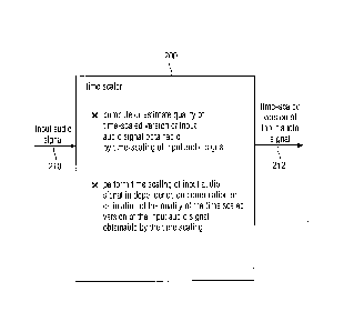
10 5.2. Time Scaler According to Fig. 2
Fig. 2 shows a block schematic diagram of a time scaler 200 according to an
embodiment
of the present invention. The time scaler 200 is configured to receive an
input audio signal
210 (for example, in the form of a sequence of samples provided by a decoder
core) and
15 provides, on the basis thereof, a time scaled version 212 of the input
audio signal. The
time scaler 200 is configured to compute or estimate a quality of a time
scaled version of
the input audio signal obtainable by a time scaling of the input audio signal.
This
functionality may be performed, for example, by a computation unit. Moreover,
the time
scaler 200 is configured to perform a time scaling of the input audio signal
210 in
20 dependence on the computation or estimation of the quality of the time
scaled version of
the input audio signal obtainable by the time scaling, to thereby obtain the
time scaled
version of the input audio signal 212. This functionality may, for example, be
performed by
a time scaling unit.
Accordingly, the time scaler may perform a quality control to ensure that
excessive
degradations of an audio quality are avoided when performing the time scaling.
For
example, the time scaler may be configured to predict (or estimate), on the
basis of the
input audio signal, whether an envisaged time scaling operation (like, for
example, an
overlap-and-add operation performed on the basis of time shifted blocks of
(audio)
samples is expected to result in a sufficiently good audio quality. In other
words, the time
scaler may be configured to compute or estimate the (expected) quality of the
time scaled
version of the input audio signal obtainable by time scaling of the input
audio signal before
the time scaling of the input audio signal is actually executed. For this
purpose, the time
scaler may, for example, compare portions of the input audio signal which are
involved in
the time scaling operation (for example, in that said portions of the input
audio signal are
to be overlapped and added to thereby perform the time scaling). To conclude,
the time
CA 02916126 2015-12-18
WO 2014/202672 PCT/EP2014/062833
21
scaler 200 is typically configured to check whether it can be expected that an
envisaged
time scaling will result in a sufficient audio quality of the time scaled
version of the input
audio signal, and to decide whether to perform the time scaling or not on the
basis
thereof. Alternatively, the time scaler may adapt any of the time scaling
parameters (for
example, a time shift between blocks of samples to be overlapped and added) in
dependence on a result of the computational estimation of the quality of the
time scaled
version of the input audio signal obtainable by the time scaling of the input
audio signal.
In the following, optional improvements of the time scaler 200 will be
described.
In a preferred embodiment, the time scaler is configured to perform an overlap-
and-add
operation using a first block of samples of the input audio signal and a
second block of
samples of the input audio signal. In this case, the time scaler is configured
to time-shift
the second block of samples with respect to the first block of samples, and to
overlap-and-
add the first block of samples and the time-shifted second block of samples,
to thereby
obtain the time scaled version of the input audio signal. For example, if a
time shrinking is
desired, the time scaler may input a first number of samples of the input
audio signal and
provide, on the basis thereof, a second number of samples of the time scaled
version of
the input audio signal, wherein the second number of samples is smaller than
the first
number of samples. In order to achieve a reduction of the number of samples,
the first
number of samples may be separated into at least a first block of samples and
a second
block of samples (wherein the first block of samples and the second block of
samples may
be overlapping or non-overlapping), and the first block of samples and the
second block of
samples may be temporally shifted together, such that the temporally shifted
versions of
the first block of samples and of the second block of samples overlap. In the
overlap
region between the shifted version(s) of the first block of samples and of the
second block
of samples, an overlap-and-add operation is applied. Such an overlap-and-add
operation
can be applied without causing substantial audible distortions if the first
block of samples
and the second block of samples are "sufficiently" similar in the overlap
region (in which
the overlap-and-add operation is performed) and preferably also in an
environment of the
overlapping region. Thus, by overlapping and adding signal portions which were
originally
not temporally overlapping, a time shrinking is achieved, since a total number
of samples
is reduced by a number of samples which have not been overlapping originally
(in the
input audio signal 210), but which are overlapped in the time scaled version
212 of the
input audio signal.
CA 02916126 2015-12-18
WO 2014/202672 PCT/EP2014/062833
22
In contrast, a time stretching can also be achieved using such an overlap-and-
add
operation. For example, a first block of samples and a second block of samples
may be
chosen to be overlapping and may comprise a first overall temporal extension.
Subsequently, the second block of samples may be time shifted with respect to
the first
block of samples, such that the overlap between the first block of samples and
the second
block of samples is reduced. If the time shifted second block of samples fits
well to the
first block of samples, an overlap-and-add can be performed, wherein the
overlap region
between the first block of samples and the time shifted version of the second
block of
samples may be shorter both in terms of a number of samples and in terms of a
time than
the original overlap region between the first block of samples and the second
block of
samples. Accordingly, the result of the overlap-and-add operation using the
first block of
samples and the time shifted version of the second block of samples may
comprise a
larger temporal extension (both in terms of time and in terms of a number of
samples)
than the total extension of the first block of samples and of the second block
of samples in
their original form.
Accordingly, it is apparent that both a time shrinking and a time stretching
can be obtained
using an overlap-and-add operation using a first block of samples of the input
audio signal
and a second block of samples of the input audio signals, wherein the second
block of
samples is time shifted with respect to the first block of samples (or wherein
both the first
block of samples and the second block of samples are time-shifted with respect
to each
other).
Preferably, the time scaler 200 is configured to compute or estimate a quality
of the
overlap-and-add operation between the first block of samples and the time-
shifted version
of the second block of samples, in order to compute or estimate the (expected)
quality of
the time scaled version of the input audio signal obtainable by the time
scaling. It should
be noted that there are typically hardly any audible artifacts if the overlap-
and-add
operation is performed for portions of the blocks of samples which are
sufficiently similar.
Worded differently, the quality of the overlap-and-add operation substantially
influences
the (expected) quality of the time scaled version of the input audio signals.
Thus,
estimation (or computation) of the quality of the overlap-and-add operation
provides for a
reliable estimate (or computation) of the quality of the time scaled version
of the input
audio signal.
CA 02916126 2015-12-18
WO 2014/202672 PCT/EP2014/062833
23
Preferably, the time scaler 200 is configured to determine the time shift of
the second
block of samples with respect to the first block of samples in dependence on
the
determination of the level of similarity between the first block of samples,
or a portion (for
example, right-sided portion) of the first block of samples, and the time
shifted second
block of samples, or a portion (for example, left sided portion) of the time
shifted second
block of samples. In other words, the time scaler may be configured to
determine, which
time shift between the first block of samples and the second block of samples
is most
appropriate in order to obtain a sufficiently good overlap-and-add result (or
at least the
best possible overlap-and-add result). However, in an additional ("quality
control") step, it
may be verified whether such a determined time shift of the second block of
samples with
respect to the first block of samples actually brings along a sufficiently
good overlap-and-
add result (or is expected to bring along a sufficiently good overlap-and-add
result).
Preferably, the time scaler determines information about a level of similarity
between the
first block of samples, or a portion (for example, right-sided portion) of the
first block of
samples, and the second block of samples, or a portion (for example, left-
sided portion) of
the second block of samples, for a plurality of different time shifts between
the first block
of samples and the second block of samples, and determines a (candidate) time
shift to
be used for the overlap-and-add operation on the basis of the information
about the level
of similarity for the plurality of different time shifts. Worded differently,
a search for a best
match may be performed, wherein information about the level of similarity for
different
time shifts may be compared, to find a time shift for which the best level of
similarity can
be reached.
Preferably, the time scaler is configured to determine the time shift of the
second block of
samples with respect to the first block of samples, which time shift is to be
used for the
overlap-and-add operation, in dependence on a target time shift information.
In other
words, a target time shift information, which may, for example, be obtained on
the basis of
an evaluation of a buffer fullness, a jitter and possibly other additional
criteria, may be
considered (taken into account) when determining which time shift is to be
used (for
example, as a candidate time shift) for the overlap-and-add operation. Thus,
the overlap-
and-add is adapted to the requirements of the system.
In some embodiments, the time scaler may be configured to compute or estimate
a quality
of the time scaled version of the input audio signal obtainable by a time
scaling of the
input audio signal on the basis of an information about a level of a
similarity between the
CA 02916126 2015-12-18
WO 2014/202672 PCT/EP2014/062833
24
first block of samples, or a portion (for example, right-sided portion) of the
first block of
samples, and the second block of samples, time-shifted by the determined
(candidate)
time-shift, or a portion (for example, left-sided portion) of the second block
of samples,
time-shifted by the determined (candidate) time shift. Said information about
the level of
similarity provides an information about the (expected) quality of the overlap-
and-add
operation, and consequently also provides an information (at least an
estimate) about the
quality of the time scaled version of the input audio signal obtainable by the
time scaling.
In some cases, the computed or estimated information about the quality of the
time scaled
version of the input audio signal obtainable by the time scaling may be used
to decide
whether the time scaling is actually performed or not (wherein the time
scaling may be
postponed in the latter case). In other words, the time scaler may be
configured to decide,
on the basis of the information about the level of similarity between the
first block of
samples, or a portion (for example, right-sided portion) of the first block of
samples, and
the second block of samples, time shifted by the determined (candidate) time
shift, or a
portion (for example, left-sided portion) of the second block of samples, time
shifted by the
determined (candidate) time shift, whether a time scaling is actually
performed (or not).
Thus, the quality control mechanism, which evaluates the computed or estimated
information on the quality of the time scaled version of the input audio
signal obtainable by
the time scaling, may actually result in omission of the time scaling (at
least for a current
block or frame of audio samples) if it is expected that an excessive
degradation of an
audio content would be caused by the time scaling.
In some embodiments, different similarity measures may be used for the initial
determination of the (candidate) time shift between the first block of samples
and the
second block of samples and for the final quality control mechanism. In other
words, the
time scaler may be configured to time shift a second block of samples with
respect to the
first block of samples, and to overlap-and-add the first block of samples and
the time
shifted second block of samples, to thereby obtain the time scaled version of
the input
audio signal, if the computation or estimation of the quality of the time
scaled version of
the input audio signal obtainable by the time scaling indicates a quality
which is larger
than or equal to a quality threshold value. The time scaler may be configured
to determine
a (candidate) time shift of the second block of samples with respect to the
first block of
samples in dependence on a determination of a level of similarity, evaluated
using a first
similarity measure, between the first block of samples, or a portion (for
example right-
sided portion) of the first block of samples, and the second block of samples,
or a portion
(for example, left-sided portion) of the second block of samples. Also, the
time scaler may
CA 02916126 2015-12-18
WO 2014/202672 PCT/EP2014/062833
be configured to compute or estimate a quality of the time scaled version of
the input
audio signal obtainable by a time scaling of the input audio signal on the
basis of an
information about a level of similarity, evaluated using a second similarity
measure,
between the first block of samples, or a portion (for example, right-sided
portion) of the
5 first block of samples, and the second block of samples, time shifted by
the determined
(candidate) time shift, or a portion (for example, left-sided portion) of the
second block of
samples, time shifted by the determined (candidate) time shift. For example,
the second
similarity measure may be computationally more complex than the first
similarity measure.
Such a concept is useful, since it is typically necessary to compute the first
similarity
10 measure multiple times per time scaling operation (in order to determine
the "candidate"
time shift between the first block of samples and the second block of samples
out of a
plurality of possible time shift values between the first block of samples and
the second
block of samples). In contrast, the second similarity measure typically only
needs to be
computed one time per time shift operation, for example as a "final" quality
check whether
15 the "candidate" time shift determined using the first (computationally
less complex) quality
measure can be expected to result in a sufficiently good audio quality.
Consequently, it is
possible to still avoid the execution of an overlap-and-add, if the first
similarity measure
indicates a reasonably good (or at least sufficient) similarity between the
first block of
samples (or a portion thereof) and the time shifted second block of samples
(or a portion
20 thereof) for the "candidate" time shift but the second (and typically
more meaningful or
precise) similarity measure indicates that the time scaling would not result
in a sufficiently
good audio quality. Thus, the application of the quality control (using the
second similarity
measure) helps to avoid audible distortions in the time scaling.
25 For example, the first similarity measure may be a cross correlation or
a normalized cross
correlation, or an average magnitude difference function, or a sum of squared
errors.
Such similarity measures can be obtained in a computationally efficient manner
and are
sufficient to find a "best match" between the first block of samples (or a
portion thereof)
and the (time-shifted) second block of samples (or a portion thereof), i.e. to
determine the
"candidate" time shift. In contrast, the second similarity measure may, for
example, be a
combination of cross correlation values or normalized cross correlation values
for a
plurality of different time shifts. Such a similarity measure provides more
accuracy and
helps to consider additional signal components (like, for example, harmonics)
or a
stationarity of the audio signal when evaluating the (expected) quality of the
time scaling.
However, the second similarity measure is computationally more demanding than
the first
CA 02916126 2015-12-18
WO 2014/202672
PCT/EP2014/062833
26
similarity measure, such that it would be computationally inefficient to apply
the second
similarity measure when searching for a "candidate" time shift.
In the following, some options for a determination of the second similarity
measure will be
described. In some embodiments, the second similarity measure may be a
combination of
cross correlations for at least four different time shifts. For example, the
second similarity
measure may be a combination of a first cross correlation value and of a
second cross
correlation value, which are obtained for time shifts which are spaced by an
integer
multiple of a period duration of a fundamental frequency of an audio content
of the first
block of samples or of the second block of samples, and of a third cross
correlation value
and a fourth cross correlation value, which are obtained for time shifts which
are spaced
by an integer multiple of the period duration of the fundamental frequency of
the audio
content. A time shift for which the first cross correlation value is obtained
may be spaced
from a time shift for which the third cross correlation value is obtained, by
an odd multiple
of half the period duration of the fundamental frequency of the audio content.
If the audio
content (represented by the input audio signal) is substantially stationary,
and dominated
by the fundamental frequency, it can be expected that the first cross
correlation value and
the second cross correlation value which may, for example, be normalized, are
both close
to one. However, since the third cross correlation value and the fourth cross
correlation
value are both obtained for time shifts which are spaced, by an odd multiple
of half the
period duration of the fundamental frequency, from the time shifts for which
the first cross
correlation value and the second cross correlation value are obtained, it can
be expected
that the third cross correlation value and the fourth cross correlation value
are opposite
with respect to the first cross correlation value and the second cross
correlation value in
case the audio content is substantially stationary and dominated by the
fundamental
frequency. Accordingly, a meaningful combination can be formed on the basis of
the first
cross correlation value, the second cross correlation value, the third cross
correlation
value and the fourth cross correlation value, which indicates whether the
audio signal is
sufficiently stationary and dominated by a fundamental frequency in a
(candidate) overlap-
and-add region.
It should be noted that particularly meaningful similarity measures can be
obtained by
computing the similarity measure q according to
q = c(p) * c(2*p) + c(3/2*p) * c(1/2*p)
CA 02916126 2015-12-18
WO 2014/202672 PCT/EP2014/062833
27
or according to
q = c(p)* c(-p) + c(-1/2*p) * c(1/2*p)
In the above, c(p) is a cross correlation value between a first block of
samples (or a
portion thereof) and a second block of samples (or a portion thereof), which
are shifted in
time (for example, with respect to an original temporal position within the
input audio
content) by a period duration p of a fundamental frequency of an audio content
of the first
block of samples and/or of the second block of samples (wherein the
fundamental
frequency of the audio content is typically substantially identical in the
first block of
samples and in the second block of samples). In other words, a cross
correlation value is
computed on the basis of blocks of samples which are taken from the input
audio content
and additionally time shifted with respect to each other by the period
duration p of the
fundamental frequency of the input audio content (wherein the period duration
p of the
fundamental frequency may be obtained, for example, on the basis of a
fundamental
frequency estimation, an auto correlation, or the like). Similarly, c(2*p) is
a cross
correlation value between a first block of samples (or a portion thereof) and
a second
block of samples (or a portion thereof) which are shifted in time by 2 * p.
Similar definitions
also apply to c(3/2*p), c(1/2*p), c(-p) and c(-1/2*p), wherein the argument of
c(.)
designates the time shift.
In the following, some mechanisms for deciding whether or not time scaling
should be
performed will be explained, which may optionally be applied in the time
scaler 200. In an
implementation, the time scaler 200 may be configured to compare a quality
value, which
is based on a computation or estimation of the (expected) quality of the time
scaled
version of the input audio signal obtainable by the time scaling, with a
variable threshold
value, to decide whether or not a time scaling should be performed.
Accordingly, the
decision whether or not to perform the time scaling can also be made dependent
on the
circumstances, like, for example, a history representing previous time
scalings.
For example, the time scaler may be configured to reduce the variable
threshold value, to
thereby reduce a quality requirement (which must be reached in order to enable
a time
scaling), in response to a finding that a quality of a time scaling would have
been
insufficient for one or more previous blocks of samples. Accordingly, it is
ensured that a
time scaling is not prevented for a long sequence of frames (or blocks of
samples) which
could cause a buffer overrun or buffer underrun. Moreover, the time scaler may
be
CA 02916126 2015-12-18
WO 2014/202672 PCT/EP2014/062833
28
configured to increase the variable threshold value, to thereby increase a
quality
requirement (which must be reached in order to enable a time scaling), in
response to the
fact that a time scaling has been applied to one or more previous blocks or
samples.
Accordingly, it can be prevented that too many subsequent blocks or samples
are time
scaled, unless a very good quality (increased with respect to a normal quality
requirement) of the time scaling can be obtained. Accordingly, artifacts can
be avoided
which would be caused if the conditions for a quality of the time scaling were
too low.
In some embodiments, the time scaler may comprise a range-limited first
counter for
counting a number of blocks of samples or a number of frames which have been
time
scaled because the respective quality requirement of the time-scaled version
of the input
audio signal obtainable by the time scaling has been reached. Moreover, the
time scaler
may also comprise a range-limited second counter for counting a number of
blocks of
samples or a number of frames which have not been time scaled because a
respective
quality requirement of the time-scaled version of the input audio signal
obtainable by the
time scaling has not been reached. In this case, the time scaler may be
configured to
compute the variable threshold value in dependence on a value of the first
counter and in
dependence on a value of the second counter. Accordingly, the "history" of the
time
scaling (and also the "quality" history) can be considered with moderate
computational
effort.
For example, the time scaler may be configured to add a value which is
proportional to the
value of the first counter to an initial threshold value, and to subtract a
value which is
proportional to the value of a second counter therefrom (for example, from the
result of the
addition) in order to obtain the variable threshold value.
In the following, some important functionalities, which may be provided in
some
embodiments of the time scaler 200 will be summarized. However, it should be
noted that
the functionalities described in the following are not essential
functionalities of the time
scaler 200.
In an implementation, the time scaler may be configured to perform the time
scaling of the
input audio signal in dependence on the computation or estimation of the
quality of the
time scaled version of the input audio signal obtainable by the time scaling.
In this case,
the computation or estimation of the quality of the time scaled version of the
input audio
signal comprises a computation or estimation of the artifacts in the time
scaled version of
CA 02916126 2015-12-18
WO 2014/202672 PCT/EP2014/062833
29
the input audio signal which would be caused by the time scaling. However, it
should be
noted that the computation or estimation of artifacts may be performed in an
indirect
manner, for example by computing a quality of an overlap-and-add operation. In
other
words, the computation or the estimation of the quality of the time scaled
version of the
input audio signal may comprise a computation or estimation of artifacts in
the time scaled
version of the input audio signal which would be caused by an overlap-and-add
operation
of subsequent blocks of samples of the input audio signal (wherein, naturally,
some time
shift may be applied to the subsequent blocks of samples).
For example, the time scaler may configured to compute or estimate the quality
of a time
scaled version of the input audio signal obtainable by a time scaling of the
input audio
signal in dependence on a level of similarity of the subsequent (and possibly
overlapping)
blocks of samples of the input audio signal.
In a preferred embodiment, the time scaler may be configured to compute or
estimate
whether there are audible artifacts in a time scaled version of the input
audio signal
obtainable by a time scaling of the input audio signal. The estimation of
audible artifacts
may be performed in an indirect manner, as mentioned in the above.
As a consequence of the quality control, the time scaling may be performed at
times
which are well suited for the time scaling and avoided at times which are not
well-suited
for the time scaling. For example, the time scaler may be configured to
postpone a time
scaling to a subsequent frame or to a subsequent block of samples if the
computation or
estimation of the quality of the time scaled version of the input audio signal
obtainable by
the timed scaling indicates an insufficient quality (for example, a quality
which is below a
certain quality threshold value). Thus, the time scaling may be performed at a
time which
is more suitable for the time scaling, such that less artifacts (in
particular, audible artifacts)
are generated. In other words, the time scaler may be configured to postpone a
time
scaling to a time when the time scaling is less audible if the computation or
estimation of
the quality of the time scaled version of the input audio signal obtainable by
the time
scaling indicates an insufficient quality.
To conclude, the time scaler 200 may be improved in a number of different
ways, as
discussed above.
CA 02916126 2015-12-18
WO 2014/202672 PCT/EP2014/062833
Moreover, it should be noted that the time scaler 200 may optionally be
combined with the
jitter buffer control 100, wherein the jitter buffer control 100 may decide
whether the
sample-based time scaling, which is typically performed by the time scaler
200, should be
used or whether a frame-based time scaling should be used.
5
5.3. Audio Decoder According to Fig. 3
Fig. 3 shows a block schematic diagram of an audio decoder 300, according to
an
10 embodiment of the present invention.
The audio decoder 300 is configured to receive an input audio content 310,
which may be
considered as an input audio representation, and which may, for example, be
represented
in the form of audio frames. Moreover, the audio decoder 300 provides, on the
basis
15 thereof, a decoded audio content 312, which may, for example, be
represented in the form
of decoded audio samples. The audio decoder 300 may, for example, comprise a
jitter
buffer 320, which is configured to receive the input audio content 310, for
example, in the
form of audio frames. The jitter buffer 320 is configured to buffer a
plurality of audio
frames representing blocks of audio samples (wherein a single frame may
represent one
20 or more blocks of audio samples, and wherein the audio samples
represented by a single
frame may be logically subdivided into a plurality of overlapping or non-
overlapping blocks
of audio samples). Moreover, the jitter buffer 320 provides "buffered" audio
frames 322,
wherein the audio frames 322 may comprise both audio frames included in the
input audio
content 310 and audio frames which are generated or inserted by the jitter
buffer (like, for
25 example, "inactive" audio frames comprising a signaling information
signaling the
generation of comfort noise). The audio decoder 300 further comprises a
decoder core
330, which receives the buffered audio frames 322 from the jitter buffer 320
and which
provides audio samples 332 (for example, blocks with audio samples associated
with
audio frames) on the basis of the audio frames 322 received from the jitter
buffer.
30 Moreover, the audio decoder 300 comprises a sample-based time scaler
340, which is
configured to receive the audio samples 332 provided by the decoder core 330
and to
provide, on the basis thereof, time-scaled audio samples 342, which make up
the
decoded audio content 312. The sample-based time scaler 340 is configured to
provide
the time-scaled audio samples (for example, in the form of blocks of audio
samples) on
the basis of the audio samples 332 (i.e., on the basis of blocks of audio
samples provided
by the decoder core). Moreover, the audio decoder may comprise an optional
control 350.
CA 02916126 2015-12-18
WO 2014/202672 PCT/EP2014/062833
31
The jitter buffer control 350, which is used in the audio decoder 300 may, for
example, be
identical to the jitter buffer control 100 according to Fig. 1. In other
words, the jitter buffer
control 350 may be configured to select a frame-based time scaling, which is
performed
by the jitter buffer 320, or a sample-based time scaling, which is performed
by the sample-
based time scaler 340 in a signal-adaptive manner. Accordingly, the jitter
buffer control
350 may receive the input audio content 310, or an information about the input
audio
content 310 as the audio signal 110, or as the information about the audio
signal 110.
Moreover, the jitter buffer control 350 may provide the control information
112 (as
described with respect to jitter buffer control 100) to the jitter buffer 320,
and the jitter
buffer control 350 may provide the control information 114, as described with
respect to
the jitter buffer control 100, to the sample-based time scaler 140.
Accordingly, the jitter
buffer 320 may be configured to drop or insert audio frames in order to
perform a frame-
based time scaling. Moreover, the decoder core 330 may be configured to
perform a
comfort noise generation in response to a frame carrying a signaling
information indicating
the generation of a comfort noise. Accordingly, a comfort noise may be
generated by the
decoder core 330 in response to the insertion of an "inactive" frame
(comprising a
signaling information indicating that a comfort noise should be generated)
into the jitter
buffer 320. In other words, a simple form of a frame-based time scaling may
effectively
result in the generation of a frame comprising comfort noise, which is
triggered by the
insertion of a "inactive" frame into the jitter buffer (which may be performed
in response to
the control information 112 provided by the jitter buffer control). Moreover,
the decoder
core may be configured to perform a "concealing" in response to an empty
jitter buffer.
Such a concealing may comprise the generation of an audio information for a
"missing"
frame (empty jitter buffer) on the basis of an audio information of one or
more frames
preceding the missing audio frame. For example, a prediction may be used,
assuming that
the audio content of the missing audio frame is a "continuation" of the audio
content of
one or more audio frames preceding the missing audio frame. However, any of
the frame
loss concealing concepts known in the art may be used by the decoder core.
Consequently, the jitter buffer control 350 may instruct the jitter buffer 320
(or the decoder
core 330) to initiate a concealing in the case that the jitter buffer 320 runs
empty.
However, the decoder core may perform the concealing even without an explicit
control
signal, based on an own intelligence.
Moreover, it should be noted that the sample-based time scaler 340 may be
equal to the
time scaler 200 described with respect to Fig. 2. Accordingly, the input audio
signal 210
may correspond to the audio samples 332, and the time scaled version 212 of
the input
CA 02916126 2015-12-18
WO 2014/202672 PCT/EP2014/062833
32
audio signal may correspond to the time scaled audio samples 342. Accordingly,
the time
scaler 340 may be configured to perform the time scaling of the input audio
signal in
dependence on a computation or estimation of the quality of the time-scaled
version of the
input audio signal obtainable by the time scaling. The sample-based time
scaler 340 may
be controlled by the jitter buffer control 350, wherein a control information
114 provided by
the jitter buffer control to the sample based time scaler 340 may indicate
whether a
sample-based time scaling should be performed or not. In addition, the control
information
114 may, for example, indicate a desired amount of time scaling to be
performed by the
sample-based time scaler 340.
It should be noted that the time scaler 300 may be supplemented by any of the
features
and functionalities described with respect to the jitter buffer control 100
and/or with
respect to the time scaler 200. Moreover, the audio decoder 300 may also be
supplemented by any other features and functionalities described herein, for
example,
with respect to Figs. 4 to 15.
5.4. Audio Decoder According to Fig. 4
Fig. 4 shows a block schematic diagram of an audio decoder 400, according to
an
embodiment of the present invention. The audio decoder 400 is configured to
receive
packets 410, which may comprise a packetized representation of one or more
audio
frames. Moreover, the audio decoder 400 provides a decoded audio content 412,
for
example in the form of audio samples. The audio samples may, for example, be
represented in a "PCM" format (i.e., in a pulse-code-modulated form, for
example, in the
form of a sequence of digital values representing samples of an audio
waveform).
The audio decoder 400 comprises a depacker 420, which is configured to receive
the
packets 410 and to provide, on the basis thereof, depacketized frames 422.
Moreover, the
depacker is configured to extract, from the packets 410, a so called "SID
flag", which
signals an "inactive" audio frame (i.e., an audio frame for which a comfort
noise
generation should be used, rather than a "normal" detailed decoding of an
audio content).
The SID flag information is designated with 424. Moreover, the depacker
provides a real-
time-transport-protocol time stamp (also designated as "RTP TS") and an
arrival time
stamp (also designated as "arrival TS"). The time stamp information is
designated with
426. Moreover, the audio decoder 400 comprises a de-jitter buffer 430 (also
briefly
CA 02916126 2015-12-18
WO 2014/202672 PCT/EP2014/062833
33
designated as jitter buffer 430), which receives the depacketized frames 422
from the
depacker 420, and which provides buffered frames 432 (and possibly also
inserted
frames) to a decoder core 440. Moreover, the de-jitter buffer 430 receives a
control
information 434 for a frame-based (time) scaling from a control logic. Also,
the de-jitter
buffer 430 provides a scaling feedback information 436 to a playout delay
estimation. The
audio decoder 400 also comprises a time scaler (also designated as "TSM") 450,
which
receives decoded audio samples 442 (for example, in the form of pulse-code-
modulated
data) from the decoder core 440, wherein the decoder core 440 provides the
decoded
audio samples 442 on the basis of the buffered or inserted frames 432 received
from the
de-jitter buffer 430. The time scaler 450 also receives a control information
444 for a
sample-based (time) scaling from a control logic and provides a scaling
feedback
information 446 to a playout delay estimation. The time scaler 450 also
provides time
scaled samples 448, which may represent time scaled audio content in a pulse-
code-
modulated form. The audio decoder 400 also comprises a PCM buffer 460, which
receives the time scaled samples 448 and buffers the time scaled samples 448.
Moreover, the PCM buffer 460 provides a buffered version of time scaled
samples 448 as
a representation of the decoded audio content 412. Moreover, the PCM buffer
460 may
provide a delay information 462 to a control logic.
The audio decoder 400 also comprises a target delay estimation 470, which
receives the
information 424 (for example the SID flag) as well as the time stamp
information 426
comprising the RTP time stamp and the arrival time stamp. On the basis of this
information, the target delay estimation 470 provides a target delay
information 472, which
describes a desirable delay, for example a desirable delay which should be
caused by the
de-jitter buffer 430, the decoder 440, the time scaler 450 and the PCM buffer
460. For
example, the target delay estimation 470 may compute or estimate the target
delay
information 472 such that the delay is not chosen unnecessarily large but
sufficient to
compensate for some jitter of the packets 410. Moreover, the audio decoder 400
comprises a playout delay estimation 480, which is configured to receive the
scaling
feedback information 436 from the de-jitter buffer 430 and the scaling
feedback
information 446 from the time scaler 460. For example, the scaling feedback
information
436 may describe a time scaling which is performed by the de-jitter buffer.
Moreover, the
scaling feedback information 446 describes a time scaling which is performed
by the time
scaler 450. Regarding the scaling feedback information 446, it should be noted
that the
time scaling performed by the time scaler 450 is typically signal adaptive
such that an
actual time scaling which is described by the scaling feedback information 446
may be
CA 02916126 2015-12-18
WO 2014/202672 PCT/EP2014/062833
34
different from a desired time scaling which may be described by the sample-
based scaling
information 444. To conclude, the scaling feedback information 436 and the
scaling
feedback information 446 may describe an actual time scaling, which may be
different
from a desired time scaling because of the signal-adaptivity provided in
accordance with
some aspects of the present invention.
Moreover, the audio decoder 400 also comprises a control logic 490, which
performs a
(primary) control of the audio decoder. The control logic 490 receives the
information 424
(for example, the SID flag) from the depacker 420. In addition, the control
logic 490
receives the target delay information 472 from the target delay estimation
470, the playout
delay information 482 from the playout delay estimation 480 (wherein the
playout delay
information 482 describes an actual delay, which is derived by the playout
delay
estimation 480 on the basis of the scaling feedback information 436 and the
scaling
feedback information 446). Moreover, the control logic 490 (optionally)
receives the delay
information 462 from the PCM buffer 460 (wherein, alternatively, the delay
information of
the PCM buffer may be a predetermined quantity). On the basis of the received
information, the control logic 490 provides the frame-based scaling
information 434 and
the sample-based scaling information 442 to the de-jitter buffer 430 and to
the time scaler
450. Accordingly, the control logic sets the frame-based scaling information
434 and the
sample-based scaling information 442 in dependence on the target delay
information 472
and the playout delay information 482 in a signal adaptive manner, considering
one or
more characteristics of the audio content (like, for example, the question
whether there is
an "inactive" frame for which a comfort noise generation should be performed
in
accordance to the signaling carried by the SID flag).
It should be noted here that the control logic 490 may perform some or all of
the
functionalities of the jitter buffer control 100, wherein the information 424
may correspond
to the information 110 about the audio signal, wherein the control information
112 may
correspond to the frame-based scaling information 434, and wherein the control
information 114 may correspond to the sample-based scaling information 444.
Also, it
should be noted that the time scaler 450 may perform some or all of the
functionalities of
the time scaler 200 (or vice versa), wherein the input audio signal 210
corresponds to the
decoded audio samples 442, and wherein the time-scaled version 212 of the
input audio
signal corresponds to the time-scaled audio samples 448.
CA 02916126 2015-12-18
WO 2014/202672 PCT/EP2014/062833
Moreover, it should be noted that the audio decoder 400 corresponds to the
audio
decoder 300, such that the audio decoder 300 may perform some or all of the
functionalities described with respect to the audio decoder 400, and vice
versa. The jitter
buffer 320 corresponds to the de-jitter buffer 430, the decoder core 330
corresponds to
5 the decoder 440, and the time scaler 340 corresponds to the time scaler
450. The control
350 corresponds to the control logic 490.
In the following, some additional details regarding the functionality of the
audio decoder
400 will be provided. In particular, the proposed jitter buffer management
(JBM) will be
10 described.
A jitter buffer management (JBM) solution is described, which can be used to
feed
received packets 410 with frames, containing coded speech or audio data, into
a decoder
440 while maintaining continuous playout. In packet-based communications, for
example,
15 voice-over-internet-protocol (VolP), the packets (for example, packets
410) are typically
subject to varying transmission times and are lost during transmission, which
leads to
inter-arrival jitter and missing packets for the receiver (for example, a
receiver comprising
the audio decoder 400). Therefore, jitter buffer management and packet loss
concealment
solutions are desired to enable a continuous output signal without stutter.
In the following, a solution overview will be provided. In the case of the
described jitter
buffer management, coded data within the received RTP packets (for example,
packets
410) is at first depacketized (for example, using the depacker 420) and the
resulting
frames (for example, frames 422) with coded data (for example, voice data
within an
AMR-WB coded frame) are fed into a de-jitter buffer (for example, de-jitter
buffer 430).
When new pulse-code-modulated data (PCM data) is required for the playout, it
needs to
be made available by the decoder (for example, by the decoder 440). For this
purpose,
frames (for example, frames 432) are pulled from the de-jitter buffer (for
example, from the
de-jitter buffer 430). By the use of the de-jitter buffer, fluctuations in
arrival time can be
compensated. To control the depth of the buffer, time scale modification (TSM)
is applied
(wherein the time scale modification is also briefly designated as time
scaling). Time scale
modification can happen on a coded frame basis (for example, within the de-
jitter buffer
430) or in a separate module (for example, within the time scaler 450),
allowing more-fine
granular adaptations of the PCM output signal (for example, of the PCM output
signal 448
or of the PCM output signal 412).
CA 02916126 2015-12-18
WO 2014/202672 PCT/EP2014/062833
36
The above described concept is illustrated, for example, in Fig. 4 which shows
a jitter
buffer management overview. To control the depth of the de-jitter buffer (for
example, de-
jitter buffer 430) and therefore also the levels of time scaling within the de-
jitter buffer (for
example, de-jitter buffer 430) and/or the TSM module (for example, within the
time scaler
450), a control logic (for example, the control logic 490, which is supported
by the target
delay estimation 470 and the playout delay estimation 480) is used. It employs
information
on the target delay (for example, information 472) and playout delay (for
example,
information 482) and whether discontinuous transmission (DTX) in conjunction
with
comfort noise generation (CNG) is currently used (for example, information
424). The
delay values are generated, for example, from separate modules (for example,
modules
470 and 480) for target and playout delay estimation, and an active/inactive
bit (SID flag)
is provided, for example, by the depacker module (for example, depacker 420).
5.4.1. Depacker
In the following, the depacker 420 will be described. The depacker module
splits RTP
packets 410 into single frames (access units) 422. It also calculates the RTP
time stamp
for all frames that are not the only or first frame in a packet. For example,
the time stamp
contained in the RTP packet is assigned to its first frame. In case of
aggregation (i.e. for
RTP packets containing more than one single frame) the time stamp for
following frames
is increased by the frame duration divided by the scale of the RTP time
stamps. In
addition, to the RTP time stamp, each frame is also tagged with the system
time at which
the RTP packet was received ("arrival time stamp"). As can be seen, the RTP
time stamp
information and the arrival time stamp information 426 may be provided, for
example, to
the target delay estimation 470. The depacker module also determines if a
frame is active
or contains a silence insertion descriptor (SID). It should be noted that
within non-active
periods, only the SID frames are received in some cases. Accordingly,
information 424,
which may for example comprise the SID flag, is provided to the control logic
490.
5.4.2. De-Jitter Buffer
The de-jitter buffer module 430 stores frames 422 received on network (for
example, via a
TCP/IP type network) until decoding (for example, by the decoder 440). Frames
422 are
inserted in a queue sorted in ascending RTP time stamp order to undo
reordering which
CA 02916126 2015-12-18
WO 2014/202672 PCT/EP2014/062833
37
could have happened on network. A frame at the front of the queue can be fed
to the
decoder 440 and is then removed (for example, from the de-jitter buffer 430).
If the queue
is empty or a frame is missing according to the time stamp difference of the
frame at the
front (of the queue) and the previously read frame, an empty frame is returned
(for
example, from the de-jitter buffer 430 to the decoder 440) to trigger packet
loss
concealment (if a last frame was active) or comfort noise generation (if a
last frame was
"SID" or inactive) in the decoder module 440.
Worded differently, the decoder 440 may be configured to generate a comfort
noise in the
case that it is signaled, in a frame, that a comfort noise should be used, for
example using
an active "SID" flag. On the other hand, the decoder may also be configured to
perform
packet loss concealment, for example, by providing predicted (or extrapolated)
audio
samples in the case that a previous (last) frame was active (i.e., comfort
noise generation
deactivated) and the jitter buffer runs empty (such that an empty frame is
provided to the
decoder 440 by the jitter buffer 430).
The de-jitter buffer module 430 also supports frame-based time scaling by
adding an
empty frame to the front (for example, of the queue of the jitter buffer) for
time stretching
or dropping the frame at the front (for example, of the queue of the jitter
buffer) for time
shrinking. In the case of non-active periods, the de-jitter buffer may behave
as if
"NO_DATA" frames were added or dropped.
5.4.3. Time Scale Modification (TSM)
In the following, the time-scale modification (TSM), which is also briefly
designated as
time scaler or sample-based time scaler herein, will be described. A modified
packet-
based WSOLA (waveform-similarity-based-overlap-add) (confer, for example,
[Lia01])
algorithm with built-in quality control is used to perform time scale
modification (briefly
designated as time scaling) of the signal. Some details can be seen, for
example, in Fig.
9, which will be explained below. A level of time scaling is signal-dependent;
signals that
would create severe artifacts when scaled are detected by a quality control
and low-level
signals, which are close to silence, are scaled by a most possible extent.
Signals that are
well time-scalable, like periodic signals, are scaled by an internally derived
shift. The shift
is derived from a similarity measure, such as a normalized cross correlation.
With an
overlap-add (OLA), the end of a current frame (also designated as "second
block of
CA 02916126 2015-12-18
WO 2014/202672
PCT/EP2014/062833
38
samples" herein) is shifted (for example, with respect to a beginning of a
current frame,
which is also designated as "first block of samples" herein) to either shorten
or lengthen
the frame.
As already mentioned, additional details regarding the time scale modification
(TSM) will
be described below, taking reference to Fig. 9, which shows a modified WSOLA
with
quality control, and also taking reference to Figs. 10a and 10b and 11.
5.4.4. PCM Buffer
In the following, the PCM buffer will be described. The time-scale
modification module 450
changes a duration of PCM frames outputted by the decoder module with a time
varying
scale. For example, 1024 samples (or 2048 samples) may be outputted by the
decoder
440 per audio frame 432. In contrast, a varying number of audio samples may be
outputted by the time scaler 450 per audio frame 432 due to the sample-based
time
scaling. In contrast, a loudspeaker sound card (or, generally, a sound output
device)
typically expects a fixed framing, for example, 20 ms. Therefore, an
additional buffer with
first-in, first-out behavior is used to apply a fixed framing on the time-
scaler output
samples 448.
When looking at the whole chain, this PCM buffer 460 does not create an
additional delay.
Rather, the delay is just shared between the de-jitter buffer 430 and the PCM
buffer 460.
Nevertheless, it is a goal to keep the number of samples stored in the PCM
buffer 460 as
low as possible, because this increases a number of frames stored in the de-
jitter buffer
430 and thus reduces a probability of late-loss (wherein the decoder conceals
a missing
frame which is received later).
The pseudo program code shown in Fig. 5 shows an algorithm to control the PCM
buffer
level. As can be seen from the pseudo program code of Fig. 5, a sound card
frame size
("soundCardFrameSize") is computed on the basis of a sample rate
("sampleRate"),
where it is assumed, as an example, that a frame duration is 20 ms.
Accordingly, a
number of samples per sound card frame is known. Subsequently, the PCM buffer
is filled
by decoding audio frames 432 (also designated as "accessUnit") until a number
of
samples in the PCM buffer ("pcmBuffer_nReadableSamples0") is no longer smaller
than
the number of samples per sound card frame ("soundCardFrameSize"). First, a
frame
CA 02916126 2015-12-18
WO 2014/202672 PCT/EP2014/062833
39
(also designated as "accessUnit") is obtained (or requested) from the de-
jitter buffer 430,
as shown at reference numeral 510. Subsequently, a "frame" of audio samples is
obtained
by decoding the frame 432 requested from the de-jitter buffer, as can be seen
at reference
512. Accordingly, a frame of decoded audio samples (for example, designated
with 442) is
obtained. Subsequently, the time scale modification is applied to the frame of
decoded
audio samples 442, such that a "frame" of time scaled audio samples 448 is
obtained,
which can be seen at reference numeral 514. It should be noted that the frame
of time
scaled audio samples may comprise a larger number of audio samples or a
smaller
number of audio samples than the frame of decoded audio samples 442 input into
the
time scaler 450. Subsequently, the frame of time scaled audio samples 448 is
inserted
into the PCM buffer 460, as can be seen at reference numeral 516.
This procedure is repeated, until a sufficient number of (time scaled) audio
samples is
available in the PCM buffer 460. As soon as a sufficient number of (time
scaled) samples
is available in the PCM buffer, a "frame" of time scaled audio samples (having
a frame
length as required by a sound playback device, like a sound card) is read out
from the
PCM buffer 460 and forwarded to the sound playback device (for example, to the
sound
card), as shown at reference numerals 520 and 522.
5.4.5. Target Delay Estimation
In the following, the target delay estimation, which may be performed by the
target delay
estimator 470, will be described. The target delay specifies the desired
buffering delay
between the time when a previous frame was played and the time this frame
could have
been received if it had the lowest transmission delay on network compared to
all frames
currently contained in a history of the target delay estimation module 470. To
estimate the
target delay, two different jitter estimators are used, one long term and one
short term
jitter estimator.
Long Term Jitter Estimation
To calculate a long term jitter, a FIFO data structure may be used. A time
span stored in
the FIFO might be different from the number of stored entries if DTX
(discontinuous
transmission mode) is used. For that reason, the window size of the FIFO is
limited in two
ways. It may contain at most 500 entries (equals 10 seconds at 50 packets per
second)
CA 02916126 2015-12-18
WO 2014/202672 PCT/EP2014/062833
and at most a time span (RTP time stamp difference between newest and oldest
packet)
of 10 seconds. If more entries are to be stored, the oldest entry is removed.
For each RTP
packet received on network, an entry will be added to the FIFO. An entry
contains three
values: delay, offset and RTP time stamp. These values are calculated from the
receive
5 time (for example, represented by the arrival time stamp) and RTP time
stamp of the RTP
packet, a shown in the pseudo code of Fig. 6.
As can be seen at reference numerals 610 and 612, a time difference between
RTP time
stamps of two packets (for example, subsequent packets) is computed (yielding
10 "rtpTimeDiff') and a difference between receive time stamps of two
packets (for example,
subsequent packets) is computed (yielding "rcvTimeDiff"). Moreover, the RTP
time stamp
is converted from a time base of a transmitting device to a time base of the
receiving
device, as can be seen at reference numeral 614, yielding "rtpTimeTicks".
Similarly, the
RTP time differences (difference between RTP time stamps) are converted to a
receiver
15 time scale /time-base of the receiving device), as can be seen at
reference numeral 616,
yielding "rtpTimeDiff'.
Subsequently, a delay information ("delay") is updated on the basis of a
previous delay
information, as can be seen at reference numeral 618. For example, if a
receive time
20 difference (i.e. a difference in times when packets have been received)
is larger than a
RTP time difference (i.e. a difference between times at which the packets have
been sent
out), it can be concluded that the delay has increased. Moreover, an offset
time
information ("offset") is computed, as can be seen at reference numeral 620,
wherein the
offset time information represents the difference between a receive time (i.e.
a time at
25 which a packet has been received) and a time at which a packet has been
sent (as
defined by the RTP time stamp, converted to the receiver time scale).
Moreover, the delay
information, the offset time information and a RTP time stamp information
(converted to
the receiver time scale) are added to the long term FIFO, as can be seen at
reference
numeral 622.
Subsequently, some current information is stored as "previous" information for
a next
iteration, as can be seen at reference numeral 624.
A long term jitter can be calculated as a difference between a maximum delay
value
currently stored in the FIFO and a minimum delay value:
CA 02916126 2015-12-18
WO 2014/202672 PCT/EP2014/062833
41
longTermJitter = longTermFifo_getMaxDelay() ¨ longTermFifo_getMinDelay();
Short Term Jitter Estimation
In the following, the short term jitter estimation will be described. The
short term jitter
estimation is done, for example, in two steps. In a first step, the same
jitter calculation as
done for long term estimation is used with the following modifications: the
window size of
the FIFO is limited to at most 50 entries and at most a time span of 1 second.
The
resulting jitter value is calculated as the difference between the 94%
percentile delay
value currently stored in the FIFO (the three highest values are ignored) and
the minimum
delay value:
shortTermJitterTmp = shortTermFifo1_getPercentileDelay(94) ¨
shortTermFifol_getMinDelay();
In a second step, first the different offsets between the short term and long
term FIFOs
are compensated for this result:
shortTermaterTmp += shortTermFifol_getMinOffset();
shortTermaterTmp -= longTermFifo_getMinOffset();
This result is added to another FIFO with a window size of at most 200 entries
and a time
span of at most four seconds. Finally, the maximum value stored in the FIFO is
increased
to an integer multiplier of the frame size and used as short term jitter:
shortTermFifo2_add( shortTermJitterTmp );
shortTermJitter = ceil( shortTermFifo2_getMax() / 20.f )* 20;
Target Delay Estimation by a Combination of Lon_gLShort Term Jitter Estimation
To calculate the target delay (for example the target delay information 472),
the long term
and short term jitter estimations (for example, as defined above as
"IongTermJitter" and
"shortTermJitter") are combined in different ways depending on the current
state. For
active signals (or signal portions, for which a comfort noise generation is
not used), a
range (for example, defined by "targetMin" and "targetMax") is used as target
delay.
CA 02916126 2015-12-18
WO 2014/202672 PCT/EP2014/062833
42
During DTX and for startup after DTX, two different values are calculated as
target delay
(for example, "targetDtx" and "targetStartUp").
Details on how the different target delay values can be computed can be seen,
for
example, in Fig. 7. As can be seen at reference numerals 710 and 712, the
values
"targetMin" and "targetMax", which assign a range for active signals, are
computed on the
basis of the short term jitter ("shortTermJitter") and the long term jitter
("longTermJitter").
The computation of the target delay during DTX ("targetDtx") is shown at
reference
numeral 714, and the calculation of the target delay value for a startup (for
example, after
DTX) ("targetStartUp") is shown at reference numeral 716.
5.4.6. Playout Delay Estimation
In the following, the playout delay estimation, which may be performed by the
playout
delay estimator 480, will be described. The playout delay specifies the
buffering delay
between the time when the previous frame was played and the time this frame
could have
been received if it had the lowest possible transmission delay on network
compared to all
frames currently contained in the history of the target delay estimation
module. It is
calculated in milliseconds using the following formula:
playoutDelay = prevPlayoutOffset - longTermFifo_getMinOffset() +
pcmBufferDelay;
The variable "prevPlayoutOffset" is recalculated whenever a received frame is
popped
from the de-jitter buffer module 430 using the current system time in
milliseconds and the
RTP time stamp of the frame converted to milliseconds:
prevPlayoutOffset = sysTime - rtpTimestamp
To avoid that "prevPlayoutOffset" will get outdated if a frame is not
available, the variable
is updated in case of frame-based time scaling. For frame-based time
stretching,
"prevPlayoutOffset" is increased by the duration of the frame, and for a frame-
based time
shrinking, "PrevPlayoutOffset" is decreased by the duration of the frame. The
variable
"pcmBufferDelay" describes the duration of time buffered in the PCM buffer
module.
5.4.7 Control Logic
CA 02916126 2015-12-18
WO 2014/202672 PCT/EP2014/062833
43
In the following, the control (for example, the control logic 490) will be
described in detail.
However, it should be noted that the control logic 800 according to Fig. 8 may
be
supplemented by any of the features and functionalities described with respect
to the jitter
buffer control 100 and vice versa. Moreover, it should be noted that the
control logic 800
may take the place of the control logic 490 according to Fig. 4, but may
optionally
comprise additional features and functionalities. Moreover, it is not required
that all of the
features and functionalities described above with respect to Fig. 4 are also
present in the
control logic 800 according to Fig. 8, and vice versa.
Fig. 8 shows a flow chart of a control logic 800, which may naturally be
implemented in
hardware as well.
The control logic 800 comprises pulling 810 a frame for decoding. In other
words, a frame
is selected for decoding, and it is determined in the following how this
decoding should be
performed. In a check 814, it is checked whether a previous frame (for
example, a
previous frame preceding the frame pulled for decoding in step 810) was active
or not. If it
is found in the check 814 that the previous frame was inactive, a first
decision path
(branch) 820 is chosen which is used to adapt an inactive signal. In contrast,
if it is found
in the check 814 that the previous frame was active, a second decision path
(branch) 830
is chosen, which is used to adapt an active signal. The first decision path
820 comprises
determining a "gap" value in a step 840, wherein the gap value describes a
difference
between a playout delay and a target delay. Moreover, the first decision path
820
comprises deciding 850 on a time scaling operation to be performed on the
basis of the
gap value. The second decision path 830 comprises selecting 860 a time scaling
in
dependence on whether an actual playout delay lies within a target delay
interval.
In the following, additional details regarding the first decision path 820 and
the second
decision path 830 will be described.
In the step 840 of the first decision path 820, a check 842 is performed
whether a next
frame is active. For example, the check 842 may check whether the frame pulled
for
decoding in the step 810 is active or not. Alternatively, the check 842 may
check whether
the frame following the frame pulled for decoding in the step 810 is active or
not. If it is
found, in the check 842, that the next frame is not active, or that the next
frame is not yet
available, the variable "gap" is set, in a step 844, as a difference between
an actual
CA 02916126 2015-12-18
WO 2014/202672 PCT/EP2014/062833
44
playout delay (defined by a variable "playoutDelay") and a DTX target delay
(represented
by variable "targetDtx"), is described above in the section "Target Delay
Estimation". In
contrast, if it is found in the check 840 that the next frame is active, the
variable "gap" is
set to a difference between the playout delay (represented by the variable
"playoutDelay")
and the startup target delay (as defined by the variable "targetStartUp") in
step 846.
In the step 850, it is first checked whether a magnitude of the variable "gap"
is larger than
(or equal to) a threshold. This is done in a check 852. If it is found that
the magnitude of
the variable "gap" is smaller than (or equal to) the threshold value, no time
scaling is
performed. In contrast, if it is found in the check 852 that the magnitude of
the variable
"gap" is larger than the threshold (or equal to the threshold values,
depending on the
implementation), it is decided that a scaling is needed. In another check 854,
it is checked
whether the value of the variable "gap" is positive or negative (i.e. if the
variable "gap" is
larger than zero or not). If it is found that the value of the variable "gap"
is not larger than
zero (i.e. negative) a frame is inserted into the de-jitter buffer (frame-
based time stretching
in step 856), such that a frame-based time scaling is performed. This may, for
example,
be signaled by the frame-based scaling information 434. In contrast, if it is
found in the
check 854, that the value of the variable "gap" is larger than zero, i.e.
positive, a frame is
dropped from the de-jitter buffer (frame-based time shrinking in step 856),
such that a
frame-based time scaling is performed. This may be signaled using the frame-
based
scaling information 434.
In the following, the second decision branch 860 will be described. In a check
862, it is
checked whether the playout delay is larger than (or equal to) a maximum
target value
(i.e. an upper limit of a target interval) which is described, for example, by
a variable
"targetMax"). If it is found that the playout delay is larger than (or equal
to) the maximum
target value, a time shrinking is performed by the time scaler 450 (step 866,
sample-
based time shrinking using the TSM), such that a sample-based time scaling is
performed.
This may be signaled, for example, by the sample-based scaling information
444.
However, if it is found in the check 862 that the playout delay is smaller
than (or equal to)
the maximum target delay, a check 864 is performed, in which it is checked
whether the
playout delay is smaller than (or equal to) a minimum target delay, which is
described, for
example, by the variable "targetMin". If it is found that the playout delay is
smaller than (or
equal to) the minimum target delay, a time stretching is performed by the time
scaler 450
(step 866, sample-based time stretching using the TSM), such that a sample-
based time
scaling is performed. This may be signaled, for example, by the sample based
scaling
CA 02916126 2015-12-18
WO 2014/202672 PCT/EP2014/062833
information 444. However, if it is found in the check 864 that the playout
delay is not
smaller than (or equal to) the minimum target delay, no time scaling is
performed.
To conclude, the control logic module (also designated as jitter buffer
management control
5 logic) shown in Fig. 8 compares the actual delay (playout delay) with the
desired delay
(target delay). In case of a significant difference, it triggers time scaling.
During comfort
noise (for example, when the SID-flag is active) frame-based time scaling will
be triggered
and executed by the de-jitter buffer module. During active periods, sample-
based time
scaling is triggered and executed by the TSM module.
Fig. 12 shows an example for target and playout delay estimation. An abscissa
1210 of
the graphical representation 1200 describes a time, and ordinate 1212 of the
graphical
representation 1200 describes a delay in milliseconds. The "targetMin" and
"targetMax"
series create a range of delay desired by the target delay estimation module
following the
windowed network jitter. The playout delay "playoutDelay" typically stays
within the range,
but the adaptation might be slightly delayed because of the signal adaptive
time scale
modification.
Fig. 13 shows the time scale operations executed in the Fig. 12 trace. An
abscissa 1310
of the graphical representation 1300 describes a time in seconds, and an
ordinate 1312
describes a time scaling in milliseconds. Positive values indicate time
stretching, negative
values time shrinking in the graphical representation 1300. During the burst,
both buffers
just get empty once, and one concealed frame is inserted for stretching (plus
20
milliseconds at 35 seconds). For all other adaptations, the higher quality
sample-based
time scaling method can be used which results in varying scales because of the
signal
adaptive approach.
To conclude, the target delay is dynamically adapted in response to an
increase of the
jitter (and also in response to a decrease of the jitter) over a certain
window. When the
target delay increases or decreases, a time scaling is typically performed,
wherein a
decision about the type of time scaling is made in a signal-adaptive manner.
Provided that
the current frame (or the previous frame) is active, a sample-based time
scaling is
performed, wherein the actual delay of the sample-based time scaling is
adapted in a
signal-adaptive manner in order to reduce artifacts. Accordingly, there is
typically not a
fixed amount of time scaling when sample-based time scaling is applied.
However, when
the jitter buffer runs empty, it is necessary (or recommendable) - as an
exceptional
CA 02916126 2015-12-18
WO 2014/202672 PCT/EP2014/062833
46
handling - to insert a concealed frame (which constitutes a frame-based time
scaling)
even though a previous frame (or a current frame) is active.
5.8. Time Scale Modification According to Fiq. 9
In the following, details regarding the time scale modification will be
described taking
reference to Fig. 9. It should be noted that the time scale modification has
been briefly
described in section 5.4.3. However, the time scale modification, which may,
for example,
be performed by the time scaler 150, will be described in more detail in the
following.
Fig. 9 shows a flowchart of a modified WSOLA with quality control, according
to an
embodiment of the present invention. It should be noted that the time scaling
900
according to Fig. 9 may be supplemented by any of the features and
functionalities
described with respect to the time scaler 200 according to Fig. 2 and vice
versa.
Moreover, it should be noted that the time scaling 900 according to Fig. 9 may
correspond
to the sample based time scaler 340 according to Fig. 3 and to the time scaler
450
according to Fig. 4. Moreover, the time scaling 900 according to Figure 9 may
take the
place of sample-based time scaling 866.
The time scaling (or time scaler, or time scaler modifier) 900 receives
decoded (audio)
samples 910, for example, in a pulse-code-modulated (PCM) form. The decoded
samples
910 may correspond to the decoded samples 442, to the audio samples 332 or to
the
input audio signal 210. Moreover, the time scaler 900 receives a control
information 912,
which may, for example, correspond to the sample based scaling information
444. The
control information 912 may, for example, describe a target scale and/or a
minimum frame
size (for example, a minimum number of samples of a frame of audio samples 448
to be
provided to the PCM buffer 460). The time scaler 900 comprises a switch (or a
selection)
920, wherein it is decided, on the basis of the information about the target
scale, whether
a time shrinking should be performed, whether a time stretching should be
performed or
whether no time scaling should be performed. For example, the switching (or
check, or
selection) 920 may be based on the sample-based scaling information 444
received from
the control logic 490.
If it is found, on the basis of the target scale information, that no scaling
should be
performed, the received decoded samples 910 are forwarded in an unmodified
form as an
CA 02916126 2015-12-18
WO 2014/202672 PCT/EP2014/062833
47
output of the time scaler 900. For example, the decoded samples 910 are
forwarded, in an
unmodified form, to the PCM buffer 460 as the "time scaled" samples 448.
In the following, a processing flow will be described for the case that a time
shrinking is to
be performed (which can be found, by the check 920, on the basis of the target
scale
information 912). In the case that a time shrinking is desired, an energy
calculation 930 is
performed. In this energy calculation 930, an energy of a block of samples
(for example,
of a frame comprising a given number of samples) is calculated. Following the
energy
calculation 930, a selection (or switching, or check) 936 is performed. If it
is found that an
energy value 932 provided by the energy calculation 930 is larger than (or
equal to) an
energy threshold value (for example, an energy threshold value Y), a first
processing path
940 is chosen, which comprises a signal adaptive determination of an amount of
time
scaling within a sample-based time scaling. In contrast, if it is found that
the energy value
932 provided by the energy calculation 930 is smaller than (or equal to) the
threshold
value (for example, the threshold value Y), a second processing path 960 is
chosen,
wherein a fixed amount of time shift is applied in a sample-based time
scaling. In the first
processing path 940, in which an amount of time shift is determined in a
signal adaptive
manner, a similarity estimation 942 is performed on the basis of the audio
samples. The
similarity estimation 942 may consider a minimum frame size information 944
and may
provide an information 946 about a highest similarity (or about a position of
highest
similarity). In other words, the similarity estimation 942 may determine which
position (for
example, which position of samples within a block of samples) is best suited
for a time
shrinking overlap-and-add operation. The information 946 about the highest
similarity is
forwarded to a quality control 950, which computes or estimates whether an
overlap-and-
add operation using the information 946 about the highest similarity would
result in an
audio quality which is larger than (or equal to) a quality threshold value X
(which may be
constant or which may be variable). If it is found, by the quality control
950, that a quality
of an overlap-and-add operation (or equivalently, of a time scaled version of
the input
audio signal obtainable by the overlap-and-add operation) would be smaller
than (or equal
to) the quality threshold value X, a time scaling is omitted and unsealed
audio samples are
output by the time scaler 900. In contrast, if it is found, by the quality
control 950, that the
quality of an overlap-and-add operation using the information 946 about the
highest
similarity (or about the position of highest similarity) would be larger than
or equal to the
quality threshold value X, an overlap-and-add operation 954 is performed,
wherein a shift,
which is applied in the overlap-and-add operation, is described by the
information 946
CA 02916126 2015-12-18
WO 2014/202672 PCT/EP2014/062833
48
about the highest similarity (or about the position of the highest
similarity). Accordingly, a
scaled block (or frame) of audio samples is provided by the overlap-and-add
operation.
The block (or frame) of time scaled audio samples 956 may, for example,
correspond to
the time scaled samples 448. Similarly, a block (or frame) of unscaled audio
samples 952,
which are provided if the quality control 950 finds that an obtainable quality
would be
smaller than or equal to the quality threshold value X, may also correspond to
the "time
scaled" samples 448 (wherein there is actually no time scaling in this case).
In contrast, if it is found in the selection 936 that the energy of a block
(or frame) of input
audio samples 910 is smaller than (or equal to) the energy threshold value Y,
an overlap-
and-add operation 962 is performed, wherein a shift, which is used in the
overlap-and-add
operation, is defined by the minimum frame size (described by a minimum frame
size
information), and wherein a block (or frame) of scaled audio samples 964 is
obtained,
which may correspond to the time scaled samples 448.
Moreover, it should be noted that a processing, which is performed in the case
of a time
stretching, is analogous to a processing performed in the time shrinking with
a modified
similarity estimation and overlap-and-add.
To conclude, it should be noted that three different cases are distinguished
in the signal
adaptive sample-based time scaling when a time shrinking or a time stretching
is selected.
If an energy of a block (or frame) of input audio samples comprises a
comparatively small
energy (for example, smaller than (or equal to) the energy threshold value Y),
a time
shrinking or a time stretching overlap-and-add operation is performed with a
fixed time
shift (i.e. with a fixed amount of time shrinking or time stretching). In
contrast, if the energy
of the block (or frame) of input audio samples is larger than (or equal to)
the energy
threshold value Y, an "optimal" (also sometimes designated as "candidate"
herein) amount
of time shrinking or of time stretching is determined by the similarity
estimation (similarity
estimation 942). In a subsequent quality control step, it is determined
whether a sufficient
quality would be obtained by such an overlap-and-add operation using the
previously
determined "optimal" amount of time shrinking or time stretching. If it is
found that a
sufficient quality could be reached, the overlap-and-add operation is
performed using the
determined "optimal" amount of time shrinking or time stretching. lf, in
contrast, it is found
that a sufficient quality may not be reached using an overlap-and-add
operation using the
previously determined "optimal" amount of time shrinking or time stretching,
the time
CA 02916126 2015-12-18
WO 2014/202672 PCT/EP2014/062833
49
shrinking or time stretching is omitted (or postponed to a later point in
time, for example,
to a later frame).
In the following, some further details regarding the quality adaptive time
scaling, which
may be performed by the time scaler 900 (or by the time scaler 200, or by the
time scaler
340, or by the time scaler 450), will be described. Time scaling methods using
overlap-
and-add (OLA) are widely available, but in general are not performing signal
adaptive time
scaling results. In the described solution, which can be used in the time
scalers described
herein, the amount of time scaling not only depends on the position extracted
by the
similarity estimation (for example, by the similarity estimation 942), which
seems optimal
for a high quality time scaling, but also on an expected quality of the
overlap-add (for
example of the overlap-add 954). Therefore, two quality control steps are
introduced in the
time scaling module (for example, in the time scaler 900, or in the other time
scalers
described herein), to decide whether the time scaling would result in audible
artifacts. In
case of potential artifacts, the time scaling is postponed up to a point in
time where it
would be less audible.
A first quality control step calculates an objective quality measure using the
position p
extracted by the similarity measure (for example, by the similarity estimation
942) as input.
In the case of a periodic signal, p will be the fundamental frequency of the
current frame.
The normalized cross correlation c() is calculated for the positions p, 2*p,
3/2*p, and
1/2*p. c(p) is expected to be a positive value and c(1/2*p) might be positive
or negative.
For harmonic signals, the sign of c(2p) should also be positive and the sign
of c(3/2*p)
should equal the sign of c(1/2*p). This relationship can be used to create an
objective
quality measure q:
q = c(p)* c(2*p) + c(3/2*p) * c(1/2*p).
The range of values for q is [-2; +2]. An ideal harmonic signal would result
in q = 2, while
very dynamic and broadband signals which might create audible artifacts during
time
scaling will produce a lower value. Due to the fact that time scaling is done
on a frame-by-
frame basis, the whole signal to calculate c(2*p) and c(3/2*p) might not be
available yet.
However, the evaluation can also be done by looking at past samples.
Therefore, c(-p)
can be used instead of c(2*p), and similarly c(-1/2*p) can be used instead of
c(3/2*p).
CA 02916126 2015-12-18
WO 2014/202672 PCT/EP2014/062833
A second quality control step compares the current value of the objective
quality measure
q with a dynamic minimum quality value qMin (which may correspond to the
quality
threshold value X) to determine if time-scaling should be applied to the
current frame.
5 There are different intentions for having a dynamic minimum quality
value: if q has a low
value because the signal is evaluated as bad to scale over a long period, qMin
should be
reduced slowly to make sure that the expected scaling is still executed at
some point in
time with a lower expected quality. On the other hand, signals with a high
value for q
should not result in scaling many frames in a row which would reduce the
quality
10 regarding long-term signal characteristics (e.g. rhythm).
Therefore, the following formula is used to calculate the dynamic minimum
quality qMin
(which may, for example, be equivalent to the quality threshold value X):
15 qMin = qMinInitial ¨ (nNotScaled * 0.1) + (nScaled * 0.2)
qMinInitial is a configuration value to optimize between a certain quality and
the delay until
a frame can be scaled with the requested quality, of which a value of 1 is a
good
compromise. nNotScaled is a counter of frames which have not been scaled
because of
20 insufficient quality (q < qMin). nScaled counts the number of frames
which have been
scaled because the quality requirement was reached (q >= qMin). The range of
both
counters is limited: they will not be decreased to negative values and will
not be increased
above a designated value which is set to be 4 by default (for example).
25 The current frame will be time-scaled by the position p if q >= qMin,
otherwise time-scaling
will be postponed to a following frame where this condition is met. The pseudo
code of
Fig. 11 illustrates the quality control for time scaling.
As can be seen, the initial value for qMin is set to 1, wherein said initial
value is
30 designated with "qMinInitial" (confer reference numeral 1110).
Similarly, a maximum
counter value of nScaled (designated as "variable qualityRise") is initialized
to 4, as can
be seen at reference numeral 1112. A maximum value of counter nNotScaled is
initialized
to 4 (variable "qualityRed"), confer reference numeral 1114. Subsequently, a
position
information p is extracted by a similarity measure, as can be seen at
reference numeral
35 1116. Subsequently, a quality value q is computed for the position
described by the
position value p in accordance with the equation which can be seen at
reference numeral
CA 02916126 2015-12-18
WO 2014/202672 PCT/EP2014/062833
51
1116. A quality threshold value qMin is computed in dependence on the variable
qMinInitial, and also in dependence on the counter values nNotScaled and
nScaled, as
can be seen at reference numeral 1118. As can be seen, the initial value
qMinInitial for
the quality threshold value qMin is reduced by a value which is proportional
to the value of
the counter nNotScaled, and increased by a value which is proportional to the
value
nScaled. As can be seen, maximum values for the counter values nNotScaled and
nScaled also determine a maximum increase of the quality threshold value qMin
and a
maximum decrease of the quality threshold value qMin. Subsequently, a check is
performed whether the quality value q is larger than or equal to the quality
threshold value
qMin, a can be seen at reference numeral 1120.
If this is the case, an overlap-add operation is executed, as can be seen at
reference
numeral 1122. Moreover, the counter variable nNotScaled is reduced, wherein it
is
ensured that said counter variable does not get negative. Moreover, the
counter variable
nScaled is increased, wherein it is ensured that nScaled does not exceed the
upper limit
defined by the variable (or constant) qualityRise. An adaptation of the
counter variables
can be seen at reference numerals 1124 and 1126.
In contrast, if it is found in the comparison shown at reference numeral 1120
that the
quality value q is smaller than the quality threshold qMin, an execution of
the overlap-and-
add operation is omitted, the counter variable nNotScaled is increased, taking
into
account that the counter variable nNotScaled does not exceed a threshold
defined by the
variable (or constant) qualityRed, and the counter variable nScaled is
reduced, taking into
account that the counter variable nScaled does not become negative. The
adaptation of
the counter variables for the case that the quality is insufficient is shown
at reference
numerals 1128 and 1130.
5.9. Time Scaler According to Figs. 10a and 10b
In the following, a signal adaptive time scaler will be explained taking
reference to Figs. 10
and 10b. Figs. 10 and 10b show a flow chart of a signal adaptive time scaling.
It should be
noted that the signal adaptive time scaling, as shown in Figs. 10a and 10b
may, for
example, be applied in the time scaler 200, in the time scaler 340, in the
time scaler 450
or in the time scaler 900.
The time scaler 1000 according to Figs. 10a and 10b, comprises an energy
calculation
1010, wherein an energy of a frame (or a portion, or a block) of audio samples
is
CA 02916126 2015-12-18
WO 2014/202672 PCT/EP2014/062833
52
computed. For example, the energy calculation 1010 may correspond to the
energy
calculation 930. Subsequently, a check 1014 is performed, wherein it is
checked whether
the energy value obtained in the energy calculation 1010 is larger than (or
equal to) an
energy threshold value (which may, for example, be a fixed energy threshold
value). It is
found, in the check 1014, that the energy value obtained in the energy
calculation 1010 is
smaller than (or equal to) the energy threshold value, it may be assumed that
a sufficient
quality can be obtained by an overlap-add operation, and the overlap-and-add
operation is
performed with a maximum time shift (to thereby obtain a maximum time scaling)
in a step
1018. In contrast, if it is found in the check 1014 that the energy value
obtained in the
energy calculation 1010 is not smaller than (or equal to) the energy threshold
value, a
search for a best match of a template segment within a search region is
performed using
a similarity measure. For example, the similarity measure may be a cross
correlation, a
normalized cross correlation, an average magnitude difference function or a
sum of
squared errors. In the following, some details regarding this search for a
best match will
be described, and it will also be explained how a time stretching or a time
shrinking can be
obtained.
Reference is now made to a graphic representation at reference numeral 1040. A
first
representation 1042 shows a block (or frame) of samples which starts at time
t1 and
which ends at time t2. As can be seen, the block of samples which starts t1
and which
ends at time t2 can be split up logically into a first block of samples, which
starts at time t1
and which ends at time t3 and a second block of samples which starts at time
t4 and
which ends at time t2. However, the second block of samples is then time
shifted with
respect to the first block of samples, which can be seen at reference numeral
1044. For
example, as a result of a first time shift, the time shifted second block of
samples starts at
time 14' and ends at time t2'. Accordingly, there is a temporal overlap
between the first
block of samples and the time shifted second block of samples between times
t4' and t3.
However, as can be seen, there is no good match (i.e. no high similarity)
between the first
block of samples and the time shifted version of the second block of samples,
for
example, in the overlap region between times t4' and t3 (or within a portion
of said overlap
region between times t4' and t3). In other words, the time scaler may, for
example, time
shift the second block of samples, as shown at reference numeral 1044, and
determine a
measure of similarity for the overlap region (or for a part of the overlap
region) between
times t4' and t3. Moreover, the time scaler may also apply an additional time
shift to the
second block of samples, as shown at reference numeral 1046, such that the
(twice) time
shifted version of the second block of samples starts at time t4" and ends at
time t2" (with
CA 02916126 2015-12-18
WO 2014/202672 PCT/EP2014/062833
53
t2" > t2' > t2 and similarly t4" > t4' > t4). The time scaler may also
determine a
(quantitative) similarity information representing a similarity between the
first block of
samples and the twice shifted version of the second block of samples, for
example,
between times t4" and t3 (or, for example, within a portion between times t4"
and t3).
Accordingly, the time scaler evaluates for which time shift of the time
shifted version of the
second block of samples the similarity, in the overlap region with the first
block of
samples, is maximized (or at last larger than a threshold value). Accordingly,
a time shift
can be determined which results in a "best match" in that the similarity
between the first
block of samples and the time shifted version of the second block of samples
is
maximized (or at least sufficiently large). Accordingly, if there is a
sufficient similarity
between the first block of samples and the twice time shifted version of the
second block
of samples within the temporal overlap region (for example between times t4"
and t3), it
can be expected, with a reliability determined by the used measure of
similarity, that an
overlap-and-add operation overlapping and adding the first block of samples
and the twice
time shifted version of the second block of samples results in an audio signal
without
substantial audible artifacts. Moreover, it should be noted that an overlap-
and-add
between the first block of samples and the twice time shifted version of the
second block
of samples results in an audio signal portion which has a temporal extension
between
times t1 and t2", which is longer than the "original" audio signal, which
extends from time
t1 to time t2. Accordingly, a time stretching can be achieved by overlapping
and adding
the first block of samples and the twice time shifted version of the second
block of
samples.
Similarly, a time shrinking can be achieved, as will be explained taking
reference to the
graphical representation at reference numeral 1050. As can be seen at
reference numeral
1052, there is an original block (or frame) of samples, which extends between
times t11
and t12. The original block (or frame) of samples can be divided, for example
into a first
block of samples which extends from time t11 to time t13 and a second block of
samples
which extends from time t13 to time t12. The second block of samples is time
shifted to
the left, as can be seen at reference numeral 1054. Consequently, the (once)
time shifted
version of the second block of samples starts at time t13' and ends at time
t12'. Also,
there is a temporal overlap between the first block of samples and the once
time shifted
version of the second block of samples between times t13' and t13. However,
the time
scaler may determine a (quantitative) similarity information representing a
similarity of the
first block of samples and of the (once) time shifted version of the second
block of
samples between times t13' and t13 (or for a portion of the time between times
t13' and
CA 02916126 2015-12-18
WO 2014/202672 PCT/EP2014/062833
54
t13) and find out that the similarity is not particularly good. Furthermore,
the time scaler
may further time shift the second block of samples, to thereby obtain a twice
time shifted
version of the second blocks of samples, which is shown at reference numeral
1056, and
which starts at time t13" and ends at time t12". Thus there is an overlap
between the first
-- block of samples and the (twice) time shifted version of the second block
of samples
between times t13" and t13. It may be found, by the time scaler, that a
(quantitative)
similarity information indicates a high similarity between the first block of
samples and the
twice time shifted version of the second block of samples between times t13"
and t13.
Accordingly, it may be concluded, by the time scaler, that an overlap-and-add
operation
-- can be performed with good quality and less audible artifacts between the
first block of
samples and the twice time shifted version of the second block of samples (at
least with
the reliability provided by the similarity measure used). Moreover, a three
times time
shifted version of the second block of samples, which is shown at reference
numeral 1058
may also be considered. The three times time shifted version of the second
block of
-- samples may start at time t13" and end as time t12". However, the three
times time
shifted version of the second block of samples may not comprise a good
similarity with the
first block of samples in the overlap region between times t13" and t13,
because the time
shift was not appropriate. Consequently, the time scaler may find that the
twice time
shifted version of the second block of samples comprises a best match (best
similarity in
-- the overlap region, and/or in an environment of the overlap region, and/or
in a portion of
the overlap region) with the first block of samples. Accordingly, the time
scaler may
perform the overlap-and-add of the first block of samples and of the twice
time shifted
version of the second block of samples, provided an additional quality check
(which may
rely on a second, more meaningful similarity measure) indicates a sufficient
quality. As a
-- result of the overlap-and-add operation, a combined block of samples is
obtained, which
extends from time t11 to time t12", and which is temporally shorter than the
original block
of samples from time t11 to time t12. Accordingly, a time shrinking can be
performed.
It should be noted that the above functionalities, which have been described
taking
-- reference to the graphical representations at reference numerals 1040 and
1050, may be
performed by the search 1030, wherein an information about the position of
highest
similarity is provided as a result of the search for a best match (wherein the
information or
value describing the position of the highest similarity is also designated
with p herein). The
similarity between the first block of samples and the time shifted version of
the second
-- block of samples within the respective overlap regions may be determined
using a cross
CA 02916126 2015-12-18
WO 2014/202672 PCT/EP2014/062833
correlation, using a normalized cross correlation, using an average magnitude
difference
function or using a sum of squared errors.
Once the information about the position of highest similarity (p) is
determined, a
5 calculation 1060 of a matching quality for the identified position (p) of
highest similarity is
performed. This calculation may be performed, for example, as shown at
reference
numeral 1116 in Fig. 11. In other words, the (quantitative) information about
the matching
quality (which may, for example, be designated with q) may be calculated using
the
combination of four correlation values, which may be obtained for different
time shifts (for
10 example, time shifts p, 2*p, 3/2*p and 1/2*p). Accordingly, the
(quantitative) information
(q) representing the matching quality can be obtained.
Taking reference now to Fig. 10b a check 1064 is performed, in which the
quantitative
information q describing the matching quality is compared with a quality
threshold value
15 qMin. This check or comparison 1064 may evaluate whether the matching
quality,
represented by a variable q, is larger than (or equal to) the variable quality
threshold value
qMin. If it is found in the check 1064 that the matching quality is sufficient
(i.e. larger than
or equal to the variable quality threshold value), an overlap-add operation is
applied (step
1068) using the position of highest similarity (which is described, for
example, by the
20 variable p). Accordingly, an overlap-and-add operation is performed, for
example,
between the first block of samples and the time shifted version of the second
block of
samples which results in a "best match" (i.e. in a highest value of a
similarity information).
For details, reference is made, for example, to the explanations made with
respect to the
graphic representation 1040 and 1050. The application of the overlap-and-add
is also
25 shown at reference numeral 1122 in Fig. 11. Moreover, an update of a
frame counter is
performed in step 1072. For example, a counter variable "nNotScaled" and a
counter
variable "nScaled", are updated, for example as described with reference to
Fig. 11 at
reference numerals 1124 and 1126. In contrast, if it is found in the check
1064 that the
matching quality is insufficient (for example, smaller than (or equal to) the
variable quality
30 threshold value qmin), the overlap-and-add operation is avoided (for
example,
postponed), which is indicated at reference numeral 1076. In this case, the
frame counters
are also updated, as shown in step 1080. The updating of the frame counters
may be
performed, for example, as shown at reference numerals 1128 and 1130 in Fig.
11.
Moreover, the time scaler described with reference to Figs. 10a and 10b may
also
35 compute the variable quality threshold value qMin, which is shown at
reference numeral
CA 02916126 2015-12-18
WO 2014/202672 PCT/EP2014/062833
56
1084. The computation of the variable quality threshold value qMin may be
performed, for
example, as shown at reference numeral 1118 in Fig. 11.
To conclude, the time scaler 1000, the functionality of which has been
described taking
reference to Figs. 10a and 10b in the form of a flow chart, may perform a
sample-based
time scaling using a quality control mechanism (steps 1060 to 1084).
5.10. Method according to Fig. 14
Fig. 14 shows a flow chart of a method for controlling a provision of a
decoded audio
content on the basis of an input audio content. The method 1400 according to
Fig. 14
comprises selecting 1410 a frame-based time scaling or a sample-based time
scaling in a
signal-adaptive manner.
In addition, it should be noted that the method 1400 can be supplemented by
any of the
features and functionalities described herein, for example, with respect to
the jitter buffer
control.
5.11. Method according to Fig. 15
Fig. 15 shows a block schematic diagram of a method 1500 for providing a time
scaled
version of an input audio signal. The method comprises computing or estimating
1510 a
quality of a time-scaled version of the input audio signal obtainable by a
time scaling of
the input audio signal. Moreover, the method 1500 comprises performing 1520
the time
scaling of the input audio signal in dependence on the computation or
estimation of the
quality of the time scaled version of the input audio signal obtainable by the
time scaling.
The method 1500 can be supplemented by any of the features and functionalities
described herein, for example, with reference to the time scaler.
6. Conclusions
To conclude, embodiments according to the invention create a jitter buffer
management
method and apparatus for high quality speech and audio communication. The
method and
the apparatus can be used together with communication codecs, such as MPEG
ELD,
AMR-WB, or future codecs. In other words, embodiments according to the
invention
CA 02916126 2015-12-18
WO 2014/202672 PCT/EP2014/062833
57
create a method and apparatus for compensation of inter-arrival jitter in
packet-based
communication.
Embodiments of the invention can be applied, for example, in the technology
called
"3GPP EVS".
In the following, some aspects of embodiments according to the invention will
be
described briefly.
The jitter buffer management solution described herein creates a system,
wherein a
number of described modules are available and are combined in the manner
described
above. Moreover, it should be noted that aspects of the invention also relate
to features of
the modules themselves.
An important aspect of the present invention is a signal adaptive selection of
a time
scaling method for adaptive jitter buffer management. The described solution
combines
frame-based time scaling and sample-based time scaling in the control logic so
that the
advantages of both methods are combined. Available time scaling methods are:
= Comfort noise insertion/deletion in DTX
= Overlap-and-add (OLA) without correlation in low signal energy (for
example, for
frames having low signal energy);
= WSOLA for active signals;
= Insertion of concealed frame for stretching in case of empty jitter
buffer.
The solution described herein describes a mechanism to combine frame-based
methods
(comfort noise insertion and deletion, and insertion of concealed frames for
stretching)
with sample-based methods (WSOLA for active signals, and unsynchronized
overlap-add
(OLA) for low-energy signals). In Fig. 8, the control logic is illustrated
that selects the
optimum technology for time-scale modification according to an embodiment of
the
invention.
According to a further aspect described herein, multiple targets for adaptive
jitter buffer
management are used. In the described solution, the target delay estimation
employs
different optimization criteria for calculating a single target playout delay.
Those criteria
result in different targets at first, optimized for high quality or low delay.
CA 02916126 2015-12-18
WO 2014/202672 PCT/EP2014/062833
58
The multiple targets for calculating the target playout delay are:
= Quality: avoid late-loss (evaluates jitter);
= Delay: limit delay (evaluates jitter).
It is an (optional) aspect of the described solution to optimize the target
delay estimation
so that the delay is limited but also late-losses are avoided and furthermore
a small
reserve in the jitter buffer is kept to increase the probability of
interpolation to enable high
quality error concealment for the decoder.
Another (optional) aspect relates to TCX concealment recovery with late
frames. Frames
that arrive late are discarded by most jitter buffer management solutions to
date.
Mechanisms have been described to use late frames in ACELP-based decoders
[Lef03].
According to an aspect, such a mechanism is also used for frames other than
ACELP
frames, e.g. frequency domain coded frames like TCX, to aid in recovery of the
decoder
state in general. Therefore, frames that are received late and already
concealed are still
fed to the decoder to improve recovery of the decoder state.
Another important aspect according to the present invention is the quality-
adaptive time
scaling, which was described above.
To further conclude, embodiments according to the present invention create a
complete
jitter buffer management solution that can be used for improved user
experience in
packet-based communications. It was an observation that the presented
solutions perform
superior than any other known jitter buffer management solution known to the
inventors.
7. Implementation Alternatives
Although some aspects have been described in the context of an apparatus, it
is clear that
these aspects also represent a description of the corresponding method, where
a block or
device corresponds to a method step or a feature of a method step.
Analogously, aspects
described in the context of a method step also represent a description of a
corresponding
block or item or feature of a corresponding apparatus. Some or all of the
method steps
may be executed by (or using) a hardware apparatus, like for example, a
microprocessor,
CA 02916126 2015-12-18
WO 2014/202672 PCT/EP2014/062833
59
a programmable computer or an electronic circuit. In some embodiments, some
one or
more of the most important method steps may be executed by such an apparatus.
The inventive encoded audio signal can be stored on a digital storage medium
or can be
transmitted on a transmission medium such as a wireless transmission medium or
a wired
transmission medium such as the Internet.
Depending on certain implementation requirements, embodiments of the invention
can be
implemented in hardware or in software. The implementation can be performed
using a
digital storage medium, for example a floppy disk, a DVD, a Blu-Ray, a CD, a
ROM, a
PROM, an EPROM, an EEPROM or a FLASH memory, having electronically readable
control signals stored thereon, which cooperate (or are capable of
cooperating) with a
programmable computer system such that the respective method is performed.
Therefore,
the digital storage medium may be computer readable.
Some embodiments according to the invention comprise a data carrier having
electronically readable control signals, which are capable of cooperating with
a
programmable computer system, such that one of the methods described herein is
performed.
Generally, embodiments of the present invention can be implemented as a
computer
program product with a program code, the program code being operative for
performing
one of the methods when the computer program product runs on a computer. The
program code may for example be stored on a machine readable carrier.
Other embodiments comprise the computer program for performing one of the
methods
described herein, stored on a machine readable carrier.
In other words, an embodiment of the inventive method is, therefore, a
computer program
having a program code for performing one of the methods described herein, when
the
computer program runs on a computer.
A further embodiment of the inventive methods is, therefore, a data carrier
(or a digital
storage medium, or a computer-readable medium) comprising, recorded thereon,
the
computer program for performing one of the methods described herein. The data
carrier,
CA 02916126 2015-12-18
WO 2014/202672 PCT/EP2014/062833
the digital storage medium or the recorded medium are typically tangible
and/or non¨
transitionary.
A further embodiment of the inventive method is, therefore, a data stream or a
sequence
5 of signals representing the computer program for performing one of the
methods
described herein. The data stream or the sequence of signals may for example
be
configured to be transferred via a data communication connection, for example
via the
Internet.
10 A further embodiment comprises a processing means, for example a
computer, or a
programmable logic device, configured to or adapted to perform one of the
methods
described herein.
A further embodiment comprises a computer having installed thereon the
computer
15 program for performing one of the methods described herein.
A further embodiment according to the invention comprises an apparatus or a
system
configured to transfer (for example, electronically or optically) a computer
program for
performing one of the methods described herein to a receiver. The receiver
may, for
20 example, be a computer, a mobile device, a memory device or the like.
The apparatus or
system may, for example, comprise a file server for transferring the computer
program to
the receiver.
In some embodiments, a programmable logic device (for example a field
programmable
25 gate array) may be used to perform some or all of the functionalities of
the methods
described herein. In some embodiments, a field programmable gate array may
cooperate
with a microprocessor in order to perform one of the methods described herein.
Generally,
the methods are preferably performed by any hardware apparatus.
30 The apparatus described herein may be implemented using a hardware
apparatus, or
using a computer, or using a combination of a hardware apparatus and a
computer.
The methods described herein may be performed using a hardware apparatus, or
using a
computer, or using a combination of a hardware apparatus and a computer.
CA 02916126 2015-12-18
WO 2014/202672 PCT/EP2014/062833
61
The above described embodiments are merely illustrative for the principles of
the present
invention. It is understood that modifications and variations of the
arrangements and the
details described herein will be apparent to others skilled in the art. It is
the intent,
therefore, to be limited only by the scope of the impending patent claims and
not by the
specific details presented by way of description and explanation of the
embodiments
herein.
CA 02916126 2015-12-18
WO 2014/202672 PCT/EP2014/062833
62
References
[Lia01] Y. J. Liang, N. Faerber, B. Girod: "Adaptive playout scheduling using
time-scale
modification in packet voice communications", 2001
[Lef03] P. Gournay, F. Rousseau, R. Lefebvre: "Improved packet loss recovery
using late
frames for prediction-based speech coders", 2003