Note : Les descriptions sont présentées dans la langue officielle dans laquelle elles ont été soumises.
[Description]
[Title of Invention]
NON-AQUEOUS ELECTROLYTE SECONDARY BATTERY AND METHOD FOR
PRODUCING SAME
[Technical Field]
[0001]
The present invention relates to a secondary battery provided with a
non-aqueous electrolyte solution. More specifically, the present invention
relates to
a non-aqueous electrolyte secondary battery in which electrical power is
inputted and
outputted via a current collector terminal welded to an electrode body, and a
method
for producing the same.
The present application claims priority on the basis of Japanese Patent
Application No. 2013-132030, which was filed on 24 June 2013.
[Background Art]
[0002]
In recent years, non-aqueous electrolyte secondary batteries such as lithium
ion secondary batteries and nickel hydrogen batteries have been used as so-
called
portable power sources for personal computers, hand-held terminals, and the
like, and
as power supplies for vehicle propulsion. In particular, lightweight lithium
ion
secondary batteries able to achieve high energy densities can be
advantageously used
as high output power sources for propelling vehicles such as electric
vehicles, hybrid
vehicles and plug-in hybrid vehicles.
[0003]
In such non-aqueous electrolyte secondary batteries, a power-generating
1
CA 2916200 2017-07-07
CA 02916200 2015-12-18
component is typically constituted by arranging a sheet-shaped positive
electrode and
a sheet-shaped negative electrode, which are obtained by providing a positive
electrode mixture layer and a negative electrode mixture layer on the surface
of a
positive electrode current collector and a negative electrode current
collector (which
may be current collector foils) respectively, so as to face each other in a
mutually
insulated state. Such power-
generating components have a layered structure
obtained by winding or layering. In addition, constitutions are known in which
current collector parts are formed so that a positive electrode current
collector or
negative electrode current collector is exposed at both edges of this type of
layered
structure, and power is inputted and outputted from an electrode body by
connecting
current collector terminals to these current collector parts. Welding is
typically used
to connect such current collector terminals. In addition, related features are
disclosed in, for example, Patent [Literature 1]
[Citation List]
[Patent Literature]
[0004]
[Patent Literature I] Japanese Patent Application Publication No.
2009-026705
[Patent Literature 2] Japanese Patent Application Publication No.
2006-339184
[Summary of Invention]
[Technical Problem]
[0005]
In the constitution disclosed in Patent Literature 1, however, constituent
materials of an active substances or the like separated from a mixture layer
provided
2
CA 02916200 2015-12-18
in a current collector due to bending or vibration of the current collector
when a
current collector terminal was welded to a current collector part. For
example, in
cases where a current collector part (a current collector foil) is welded to a
current
collector terminal by means of ultrasonic welding, which can advantageously
join thin
metal members such as foils to each other, the current collector part and
current
collector terminal are continuously subjected to ultrasonic vibrations in
order to bring
about diffusion of metal atoms that constitute the current collector part and
current
collector terminal. These vibrations are transmitted as far as the mixture
layer
provided in the current collector, which leads to concerns regarding
separation from
the mixture layer of active substance particles that constitute the porous
mixture layer
(this is also known as so-called "powder fall-off') and the mixture layer per
se
detaching from the current collector.
[0006]
Meanwhile, production times need to be shortened in order to produce
high-capacity non-aqueous electrolyte secondary batteries at lower cost. An
effective means for shortening production times is to reduce the quantity of
solvent in
an electrode mixture coated on a current collector when producing a positive
electrode
or negative electrode, thereby reducing the time required to dry the coated
electrode
mixture layer. Therefore, investigations have been carried out into methods
for
producing non-aqueous electrolyte secondary batteries by reducing the quantity
of
solvent in electrode mixtures or by not using solvents at all. However, by
reducing
the quantity of solvent, defects in terms of the dispersion of binders in
electrode
mixtures readily occur, fluctuations occur in the state of integration of
materials such
as electrode active substances that constitute mixture layers, and the
probability of
active substance particle separation and mixture layer detachment during
welding
3
CA 02916200 2015-12-18
significantly increases.
[0007]
In view of such circumstances, an objective of the present invention is to
provide, for example, a non-aqueous electrolyte secondary battery in which,
even
when a current collector terminal is welded to a current collector part using
a method
that involves vibrations, such as ultrasonic welding, separation of the
constituent
materials of a mixture layer and detachment of the mixture layer are
effectively
suppressed. Another related objective is to provide a method by which such a
secondary battery can be produced with high productivity and at lower cost.
[Solution to Problem]
[0008]
In order to solve the problems mentioned above, the present invention
provides a non-aqueous electrolyte secondary battery having a layered
structure in
which power-generating components including an electrode are layered. In this
non-aqueous electrolyte secondary battery, the electrode includes an electrode
current
collector and an electrode mixture layer provided in a part of the electrode
current
collector. The electrode current collector includes a current collector part
that is not
provided with the electrode mixture layer of the electrode current collector.
The
current collector part includes a weld section that is welded to the current
collector
part of another electrode current collector that is adjacent in the layering
direction.
In addition, the current collector part is characterized by being provided
with a
vibration-absorbing member between the weld section and the electrode mixture
layer. Typically, this weld section can be a weld section formed by welding a
current
collector terminal to the outermost surface of each of a plurality of power-
generating
components in a layered structure. Therefore, cases in which the molten metal
of the
4
CA 02916200 2015-12-18
weld section corresponds to the composition of the electrode current collector
and
cases in which the molten metal of the weld section consists of components of
the
electrode current collector and the current collector terminal are to be
considered. It
is preferable for the vibration-absorbing member to be provided only in a part
of a
region between the weld section and the electrode mixture layer.
[0009]
Because the vibration-absorbing member is provided between the electrode
mixture layer and the weld section in the constitution described above,
transmission
of shocks or vibrations to the electrode mixture layer can be suppressed when,
for
example, welding current collector parts in the layering direction when
joining current
collector terminals. In addition, by providing the vibration-absorbing member
in the
current collector part, bending of the current collector part due to
vibrations can be
suppressed. Therefore, the present invention provides a non-aqueous
electrolyte
secondary battery provided with a high quality electrode mixture layer in
which
separation of constituent materials of an active substance or the like from a
mixture
layer provided on a current collector and detachment of the mixture layer per
se,
which are caused by shocks, vibrations or bending, are reduced. In addition,
when
this non-aqueous electrolyte secondary battery is subjected to high rate
charging and
discharging, even if loosened or detached electrode mixture layer constituent
materials are present, it is possible to suppress discharge of these materials
to outside
the electrode due to the presence of the vibration-absorbing member, and it is
possible
to achieve the effect of reducing high rate degradation.
[0010]
In another aspect, the present invention provides a method for producing the
non-aqueous electrolyte secondary battery described above. This production
method
CA 02916200 2015-12-18
is characterized by including the following steps: preparing the electrode
current
collector, an electrode mixture for forming the electrode mixture layer, and a
vibration-absorbing member-forming composition for forming the
vibration-absorbing member; forming the electrode mixture layer by supplying
the
electrode mixture to the electrode current collector while allowing the
current
collector part to remain unsupplied with electrode mixture; preparing the
electrode by
forming the vibration-absorbing member on the current collector part of the
electrode
current collector by supplying the vibration-absorbing member-forming
composition
to a part of a region between the weld section and the electrode mixture layer
while
allowing at least the weld section to remain unsupplied with the composition;
constructing a layered structure by layering a plurality of power-generating
components that include the electrode; welding, at the weld section, the
current
collector part of the layered structure to the current collector part of
another electrode
current collector that is adjacent in the layering direction; welding the
current
collector terminal to the weld section, which was allowed to remain unsupplied
with
the composition in the current collector part; and constructing a non-aqueous
electrolyte secondary battery provided with the layered structure. Moreover,
it is
preferable for the welding to be ultrasonic welding.
[0011]
According to this constitution, because the vibration-absorbing member is
reliably formed between the weld section and the electrode mixture layer
before the
current collector terminals are joined and the current collector parts are
welded in the
layering direction, it is possible to produce a non-aqueous electrolyte
secondary
battery in which shocks and vibrations that occur during welding are reliably
prevented from being transmitted from the weld section to the electrode
mixture layer.
6
CA 02916200 2015-12-18
In addition, ultrasonic welding (also called ultrasonic pressure welding)
typically involves sandwiching materials to be welded between horns or anvils
and
applying ultrasonic vibrations while applying pressure, thereby subjecting
solid phase
surfaces of the materials to be welded to solid phase bonding. This type of
ultrasonic welding involves a lower welding temperature than resistance
welding or
the like, and therefore has less thermal impact on materials being welded and
can be
used to weld thin materials such as foils, but because vibrations occur during
welding,
there is the problem of these vibrations being transmitted to materials being
welded.
In particular, when welding an electrode current collector provided with a
relatively
brittle electrode mixture layer, there are concerns regarding problems such as
powder
fall-off from the electrode mixture layer and loosening or detachment of the
electrode
mixture layer.
Because the production method of the present invention can effectively
suppress shocks and vibrations during welding, the use of ultrasonic welding
to bond
a current collector part to a current collector terminal in an electrode is
preferred
because the effects achieved thereby are significant. Therefore, the present
invention
provides a production method able to ameliorate problems such as powder fall-
off
from the electrode mixture layer and loosening or detachment of the electrode
mixture
layer even in cases where the non-aqueous electrolyte secondary battery is
produced
using an ultrasonic welding process.
[0012]
In a preferred aspect of the non-aqueous electrolyte secondary battery
disclosed here, the vibration-absorbing member is characterized by being
formed in
such a way that the length of the vibration-absorbing member in a direction
along the
boundary between the electrode mixture layer and the current collector part is
equal to
7
CA 02916200 2015-12-18
or greater than the length of the weld section in this direction and shorter
than the
length of the electrode current collector in this direction.
In this constitution, because the vibration-absorbing member is disposed in
such a way as to cut across the pathway by which shocks and vibrations that
occur
during welding are directly transmitted to the electrode mixture layer, shocks
and
vibrations can be efficiently suppressed by the vibration-absorbing member. In
addition, by setting the length of the vibration-absorbing member in a
direction that
cuts across this transmission pathway to be less than the width of the
electrode current
collector, impregnation of an electrolyte solution into the electrode mixture
layer is
not greatly impaired even in cases where a non-aqueous electrolyte solution is
used as
an electrolyte. Therefore, a non-aqueous electrolyte secondary battery
provided with
a higher quality electrode is provided.
In addition, the invention disclosed here also provides a method for producing
such a non-aqueous electrolyte secondary battery.
[0013]
In a preferred aspect of the non-aqueous electrolyte secondary battery
disclosed here, the vibration-absorbing member is characterized by being
formed in a
band-like manner in the direction along the boundary mentioned above so as to
be in
contact with the electrode mixture layer.
According to this constitution, it is possible to reliably suppress
transmission
of shocks and vibrations that occur during welding to the vibration-absorbing
member,
and it is possible to prevent separation of constituent materials at the edge
of the
electrode mixture layer and detachment of the electrode mixture layer. In this
way, a
non-aqueous electrolyte secondary battery having a higher quality electrode
mixture
layer is provided.
8
CA 02916200 2015-12-18
In addition, the invention disclosed here also provides a method for producing
such a non-aqueous electrolyte secondary battery.
[0014]
In a preferred aspect of the non-aqueous electrolyte secondary battery
disclosed here, the electrode is characterized by including a positive
electrode in
which a positive electrode mixture layer is formed on a surface of a positive
electrode
current collector, and characterized in that the thickness of the vibration-
absorbing
member provided in the positive electrode is at least 50% of the thickness of
the
positive electrode mixture layer.
According to this constitution, even if vibrations occur when, for example, an
electrode is welded to a current collector terminal, the quantity of
constituent material
that separates from the positive electrode mixture layer (the degree of powder
fall-off)
can be greatly reduced. For example, the degree of powder fall-off can be
reduced to
approximately one tenth or less of the degree of powder fall-off that occurs
in cases
where a vibration-absorbing member is not provided. In this way, a non-aqueous
electrolyte secondary battery having a higher quality positive electrode
mixture layer
is provided.
In addition, the invention disclosed here also provides a method for producing
such a non-aqueous electrolyte secondary battery.
[0015]
In a preferred aspect of the non-aqueous electrolyte secondary battery
disclosed here, the electrode is characterized by including a negative
electrode in
which a negative electrode mixture layer is formed on a surface of a negative
electrode current collector, and characterized in that the thickness of the
vibration-absorbing member provided in the negative electrode is equal to or
more
9
CA 02916200 2015-12-18
than 45% of the thickness of the negative electrode mixture layer.
According to this constitution, even if vibrations occur when, for example, an
electrode is welded to a current collector terminal, the quantity of
constituent material
that separates from the negative electrode mixture layer (the degree of powder
fall-off) can be greatly reduced. For example, the degree of powder fall-off
can be
reduced to approximately one tenth or less of the degree of powder fall-off
that occurs
in cases where a vibration-absorbing member is not provided. In this way, a
non-aqueous electrolyte secondary battery having a higher quality negative
electrode
mixture layer is provided.
In addition, the invention disclosed here also provides a method for producing
such a non-aqueous electrolyte secondary battery.
[0016]
In a preferred aspect of the non-aqueous electrolyte secondary battery
disclosed here, the vibration-absorbing member is characterized by having a
porous
structure constituted from resin particles that are not oxidized at a voltage
of driving
the electrode.
According to this constitution, a shock- and vibration-buffering effect can be
achieved by the vibration-absorbing member, and because the vibration-
absorbing
member is a porous structure, it is possible to improve the state of
impregnation of an
electrolyte solution in cases where a non-aqueous electrolyte solution is used
as an
electrolyte while suppressing discharge of loosened or detached constituent
materials
of the electrode mixture layer. Therefore, a non-aqueous electrolyte secondary
battery provided with a higher quality electrode mixture layer, which can be
expected
to achieve a good state of electrolyte solution impregnation and good output
characteristics, is provided. In addition, because the vibration-absorbing
member is
CA 02916200 2015-12-18
formed as a porous structure by means of resin particles, the vibration-
absorbing
member can be made to be relatively lightweight, and it is possible to prevent
an
increase in the weight of the non-aqueous electrolyte secondary battery.
Moreover, by using particles consisting of a thermoplastic resin as these
resin
particles and bonding the particles to each other by means of; for example,
fusion
bonding or the like, it is possible to form the vibration-absorbing member
without
using a binder. Preferably, this type of thermoplastic resin is polyethylene
or
polypropylene, and in particular polypropylene.
In addition, the invention disclosed here also provides a method for producing
such a non-aqueous electrolyte secondary battery.
[0017]
In a preferred aspect of the non-aqueous electrolyte secondary battery
disclosed here, the battery is characterized in that the porosity of the
vibration-absorbing member is 60% or lower.
The vibration-absorbing member is a porous structure, and therefore prevents
penetration of an electrolyte solution from being impaired, but in order to
achieve a
satisfactory shock- and vibration-suppressing effect, it is desirable for the
porosity to
be 60% or lower, as mentioned above. Therefore, a non-aqueous electrolyte
secondary battery provided with a high quality electrode mixture layer, in
which a
good balance is achieved between a vibration-buffering effect and an
electrolyte
solution penetration impairment suppression effect, is provided.
In addition, the invention disclosed here also provides a method for producing
such a non-aqueous electrolyte secondary battery.
[0018]
Moreover, the "porosity (s)" in the present specification is defined as the
value
11
CA 02916200 2015-12-18
calculated using the formula below when a sample that is cut to a prescribed
size from
a vibration-absorbing member disposed on an electrode surface is measured,
with the
measured area being denoted by S, the thickness being denoted by h, the weight
being
denoted by W, and the true density of the vibration-absorbing member being
denoted
by p.
e (%) = 100-W-:-(Sxhxp)
Moreover, in cases where the vibration-absorbing member is constituted from
a plurality of materials, the true density (p) of the vibration-absorbing
member can be
considered to be the sum of the values obtained by multiplying the proportion
of each
constituent material by the true density (pn) of each constituent material. In
the
present specification, the porosity (p
) is calculated for a sample cut (punched) so as to have a circular shape with
a
diameter of 3 mm.
[0019]
In a preferred aspect of the non-aqueous electrolyte secondary battery
disclosed here, the power-generating component may be constituted from a
layered
electrode body obtained by layering a plurality of the positive electrodes and
a
plurality of the negative electrodes on each other in a mutually insulated
state.
Alternatively, in a preferred aspect of the non-aqueous electrolyte secondary
battery
disclosed here, the power-generating component may be constituted from a wound
electrode body in which a layered structure is formed by overlaying and
winding a
long sheet-shaped positive electrode and a long sheet-shaped negative
electrode on
each other in a mutually insulated state. In at least one of the positive
electrode and
negative electrode in these electrode bodies, the current collector part is
joined in an
integrated manner at the weld section in the layering direction of the
electrode. For
12
CA 02916200 2015-12-18
example, current collector terminals are joined by means of welding at the
outermost
weld section of this integrated current collector part. In a non-aqueous
electrolyte
secondary battery having this type of constitution also, a vibration-absorbing
member
is disposed between the weld section and the electrode mixture layer in each
electrode.
According to this constitution, because a vibration-absorbing member is
disposed in each of the plurality of electrodes, transmission to the electrode
mixture
layer of shocks and vibrations that occur during welding can be reliably
suppressed in
each electrode. Therefore, because a current collector terminal is welded to
an
electrode body provided with a layered structure having a large number of
layers,
even if the magnitude of shocks and vibrations increase due to the input power
increasing during welding or if the welding period increases, powder fall-off
from the
mixture layer and loosening or detachment of the mixture layer can be
advantageously
suppressed. In this way, a non-aqueous electrolyte secondary battery provided
with
a high quality layered electrode body or wound electrode body is provided.
In addition, the invention disclosed here also provides a method for producing
such a non-aqueous electrolyte secondary battery.
[Brief Description of Drawings]
[0020]
[FIG. 1] FIG. 1 is a longitudinal sectional view that schematically
illustrates
the cross sectional structure of a non-aqueous electrolyte secondary battery
according
to one embodiment.
[FIG. 2] FIG 2 is a planar view showing an example of a constitution of an
electrode according to one working example.
[FIG 3] FIG 3 is a cross-sectional schematic diagram that illustrates the
13
CA 02916200 2015-12-18
manner in which a current collector terminal is joined to a current collector
part in an
electrode body according to one embodiment.
[FIG. 4] FIG 4 (a) and (b) are planar views showing examples of the manner in
which a vibration-absorbing member is disposed in an electrode.
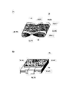
[FIG. 5] FIG. 5 shows perspective views that show the manner in which a
current collector terminal is connected to (a) a wound electrode body or (b) a
layered
electrode body according to one embodiment.
[FIG. 6] FIG 6 is a schematic diagram that illustrates the constitution of a
wound electrode body according to one embodiment.
[FIG. 7] FIG. 7 is a graph that shows the relationship between the thickness
of
a vibration-absorbing member and the degree of powder fall-off caused by
welding in
a working example.
[FIG 8] FIG 8 is a graph that shows the relationship between the manner in
which a vibration-absorbing member is disposed in an electrode and the
resistance
behavior during electrolyte solution impregnation in a working example.
[Description of Embodiments]
[0021]
Preferred embodiments of the present invention will now be explained while
referring
to the drawings as appropriate. Matters which are essential for carrying out
the
invention and which are matters other than those explicitly mentioned in the
present
specification are matters that a person skilled in the art could understand to
be matters
of design on the basis of the prior art in this technical field. The present
invention
can be carried out on the basis of the matters disclosed in the present
specification and
common general technical knowledge in this technical field. Moreover, in the
drawings shown below, components/parts that perform the same action are
denoted by
14
CA 02916200 2015-12-18
the same symbols, and duplicate explanations will be omitted or simplified. In
addition, dimensions shown in the drawings (lengths, widths, thicknesses, and
so on)
do not necessarily reflect actual dimensions.
[0022]
Although not intending to place particular limitations on the present
invention,
the constitution of a non-aqueous electrolyte secondary battery according to
the
present invention will now be explained in detail by using, as an example, a
non-aqueous electrolyte secondary battery 100 that is a preferred embodiment,
as
shown in FIG 1 to 6. The non-aqueous electrolyte secondary battery 100 shown
in
FIG 1 has a form whereby a wound electrode body 20, which is wound into a flat
shape, and a non-aqueous electrolyte (not shown) are housed in a battery case
10
having a flat rectangular shape. In addition, the non-aqueous electrolyte
secondary
battery 100 provided by the present invention is essentially constituted so as
to
include a layered structure obtained by layering power-generating components
that
include electrodes 30 and 40. Here, the power-generating components can
typically
be constituted by disposing positive electrodes 30 and negative electrodes 40
so as to
face each other in a mutually insulated state. In addition, the layered
structure
obtained by layering these power-generating components s can typically be
achieved
by means of an electrode body 20 having a layered structure in which positive
electrodes 30 and negative electrodes 40 are layered on each other. Typically,
the
non-aqueous electrolyte secondary battery 100 is provided with this electrode
body 20
and current collector terminals 62 and 72, which are used to output power from
the
electrode body 20.
[0023]
In addition, FIG. 2 is a diagram showing an embodiment of an electrode 30 or
CA 02916200 2015-12-18
40 in a constitution that is characteristic of the non-aqueous electrolyte
secondary
battery 100 of the present invention. The positive electrode 30 in the non-
aqueous
electrolyte secondary battery 100 of the present invention includes a positive
electrode current collector 32 and a positive electrode mixture layer 34 that
is
provided on a part of the positive electrode current collector 32. This
positive
electrode current collector 32 has a positive electrode current collector part
36 that is
not provided with the positive electrode mixture layer 34, and the positive
electrode
current collector part 36 includes a weld section 64, which is formed by
welding the
positive electrode current collector part 36 to the current collector part 36
of another
positive electrode current collector 32 that is adjacent in the layering
direction. In
addition, the negative electrode 40 includes a negative electrode current
collector 42
and a negative electrode mixture layer 44 that is provided on a part of the
negative
electrode current collector 42. This negative electrode current collector 42
has a
negative electrode current collector part 46 that is not provided with the
negative
electrode mixture layer 44, and the negative electrode current collector part
46
includes a weld section 74, which is formed by welding the negative electrode
current
collector part 46 to the current collector part 46 of another negative
electrode current
collector 42 that is adjacent in the layering direction. In addition, in a
layered
structure obtained by layering power-generating components that include
electrodes
30 and 40 having these constitutions, a positive electrode current collector
terminal 62
is typically joined by means of welding to the positive electrode current
collector part
36 at the weld section 64 provided at a part of the outermost positive
electrode current
collector part 36. In addition, a negative electrode current collector
terminal 72 is
joined by means of welding to the negative electrode current collector part 46
at the
weld section 74 provided at a part of the outermost negative electrode current
16
CA 02916200 2015-12-18
collector part 46.
In addition, a vibration-absorbing member 80 is provided between the weld
section 64 and the positive electrode mixture layer 34 in the positive
electrode current
collector part 36. In addition, a vibration-absorbing member 80 is provided
between
the weld section 74 and the negative electrode mixture layer 44 in the
negative
electrode current collector part 46. This vibration-absorbing member 80 is
provided
only in a part of a region between the weld section 64 or 74 and the electrode
mixture
layer 34 or 44. That is, a section in which the current collector part 36 or
46 is
exposed is allowed to remain in the region between the weld section 64 or 74
and the
electrode mixture layer 34 or 44. Moreover, the vibration-absorbing member 80
is
provided on both surfaces of all the electrode current collectors 32 and 42 in
FIG 3,
but the present invention is not limited to such an embodiment. For example,
it is
possible for the vibration-absorbing member 80 to be provided on only some of
the
electrode current collectors 32 and 42. In addition, it
is possible for the
vibration-absorbing member 80 to be provided on only one surface of some or
all of
the electrode current collectors 32 and 42. For example, it is possible for
the
vibration-absorbing member not to be provided on the outermost electrode
current
collectors 32 and 42.
[0024]
By providing the vibration-absorbing member 80 between the weld section 64
or 74 and the electrode mixture layer 34 or 44 in this way, it is possible to
reliably
reduce the magnitude of shocks and vibrations that are transmitted from the
weld
sections 64 and 74 to the electrode mixture layers 34 and 44 (hereinafter also
referred
to simply as a "vibration-absorbing effect"). For example, it is possible to
suppress
the transmission of shocks and vibrations, which occur when welding the
electrode
17
CA 02916200 2015-12-18
terminals 62 and 72 at the weld sections 64 and 74. from the weld sections 64
and 74
to the electrode mixture layers 34 and 44. In addition, it is possible to
suppress the
transmission of shocks and vibrations from the outside (outside the battery
case 10) to
the electrode mixture layers 34 and 44 via the electrode terminals 62 and 72.
That is,
in the present invention, the vibration-absorbing member 80 can be understood
to be a
structural member that exhibits a vibration-isolating effect that prevents
breakage or
damage of the electrode mixture layers 34 and 44 by any type of unwanted
external
shocks and vibrations.
[0025]
Moreover, in the case shown in FIG. 2, the vibration-absorbing member 80 is
formed in such a way that the length of the vibration-absorbing member in a
direction
along the boundary between the electrode mixture layer 34 or 44 and the
current
collector part 36 or 46 is at least as long as the length of the weld section
64 or 74 in
this direction and shorter than the length of the electrode current collector
32 or 42 in
this direction. In this way, the vibration-absorbing member 80 can suppress
shocks
and vibrations that are directly transmitted from the weld sections 64 and 74
to the
electrode mixture layers 34 and 44 and suppress shocks and vibrations that are
transmitted in a somewhat diffused manner from the weld sections 64 and 74 to
the
electrode mixture layers 34 and 44, and it is possible to achieve a higher
vibration-absorbing effect. Furthermore, the vibration-absorbing member 80 is
formed in a band-like manner along the boundary between the electrode mixture
layer
34 or 44 and the current collector part 36 or 46 so as to be in contact with
the
electrode mixture layer 34 or 44. Forming the vibration-absorbing member in
this
way is preferred from the perspective of being able to more reliably reduce
shocks
and vibrations transmitted from the weld sections 64 and 74 to the electrode
mixture
18
CA 02916200 2015-12-18
layers 34 and 44. In addition, by forming the vibration-absorbing member 80 so
as
to be adjacent to the electrode mixture layer 34 or 44, it is possible to
achieve the
effect of suppressing separation of mixture layer constituent materials at the
edges of
a relatively brittle electrode mixture layer 34 or 44 and suppressing
detachment of the
mixture layer 34 or 44. Furthermore, forming the vibration-absorbing member 80
so
as to be adjacent to the electrode mixture layers 34 and 44 has the advantage
of being
able to easily form the vibration-absorbing member 80 with a high thickness.
[0026]
However, the vibration-absorbing member 80 is not limited to such examples,
and can be formed so as to be completely separated from the electrode mixture
layer
34 or 44, as shown in FIG 4 (a), for example. Alternatively, the vibration-
absorbing
member 80 can be formed so as to be partially separated from the electrode
mixture
layer 34 or 44, although this is not explicitly shown in the drawings. In
addition, in
the case shown in FIG. 2, the vibration-absorbing member 80 is formed in a
continuous band-like manner, but is not limited to this example, and can be
formed in
an intermittent band-like manner, as shown in FIG. 4 (b), for example. In
order to
clearly show that the vibration-absorbing member 80 is not formed continuously
in
FIG. 4 (b), sections where the vibration-absorbing member 80 is not formed are
shown as being relatively broad and numerous, but the vibration-absorbing
member
80 is not limited to this example, and the form of a vibration-absorbing
member 80
having an intermittent band-like shape can be arbitrarily set according to the
desired
operation or the like.
Moreover, this type of band-like vibration-absorbing member 80 is not
particularly limited, but it is generally preferable for the dimension
perpendicular to
the boundary between the electrode mixture layer 34 or 44 and the current
collector
19
CA 02916200 2015-12-18
part 36 or 46 to be 1 to 7 mm. If the vibration-absorbing member 80 is formed
with
such a dimension, it is possible to satisfactorily achieve the effect of
suppressing the
transmission of shocks and vibrations without being greatly affected by the
physical
structure of the battery or the like.
Moreover, the shape of the vibration-absorbing member 80 is not particularly
limited and is not necessarily limited to being rectangular, and may be, for
example,
an irregular shape consisting of arbitrary curved shapes and patterns.
[0027]
Meanwhile, because the vibration-absorbing member 80 is formed when the
electrode body 20 is constructed, the vibration-absorbing member 80 can exert
resistance to the penetration of a non-aqueous electrolyte solution in the
case of a
secondary battery 100 which uses a non-aqueous electrolyte solution as a
non-aqueous electrolyte and in which the non-aqueous electrolyte solution is
allowed
to penetrate from the weld sections 64 and 74 in the electrode body 20 towards
the
electrode mixture layers 34 and 44 following construction. In such cases, it
is
preferable for the vibration-absorbing member 80 to be formed in such a way
that the
length of the vibration-absorbing member in a direction along the boundary
between
the electrode mixture layer 34 or 44 and the current collector part 36 or 46
is shorter
than the length of the electrode current collector 32 or 42 in this direction.
Here, this
length can be considered to be the overall length of the vibration-absorbing
member
80 in this direction. For example, in cases where the vibration-absorbing
member 80
is formed in an intermittent band-like manner, this length can be taken to be
the total
length of the individual vibration-absorbing members 80 in this direction.
CA 02916200 2015-12-18
[0028]
In addition, the vibration-absorbing effect of the vibration-absorbing member
80 can vary according to the volume of the vibration-absorbing member 80. That
is,
the vibration-absorbing effect can increase as the volume of the vibration-
absorbing
member 80 disposed in the electrodes 30 and 40 increases. Meanwhile, the
non-aqueous electrolyte solution penetration impairment behavior can become
significant as the vibration-absorbing member 80 is provided across a broader
area of
the region between the weld section 64 or 74 and the electrode mixture layer
34 or 44
(for example, the whole of this region). Therefore, in order to achieve a good
balance between the vibration-absorbing effect and reducing the penetration
impairment behavior, it is preferable for the vibration-absorbing member 80 to
be
formed at a higher thickness for a given volume. By forming the
vibration-absorbing member 80 so as to have a high thickness, transmission of
shocks
and vibrations, which occur when the electrode terminals 62 and 72 are welded
to the
weld sections 64 and 74, to the electrode mixture layers 34 and 44 can be more
effectively suppressed and the quantity of constituent material that separates
from the
electrode mixture layers 34 and 44 (the degree of powder fall-off) can be
reduced.
In addition, the non-aqueous electrolyte solution penetration impairment
behavior can
be advantageously suppressed. Moreover, by increasing the thickness of the
vibration-absorbing member 80, it is possible to achieve the effect of
suppressing
discharge of the electrode mixture layers 34 and 44 from the electrode body 20
even
in the unlikely event that constituent materials of the electrode mixture
layers 34 and
44 become detached or loosened. This is a preferred constitution for the
non-aqueous electrolyte secondary battery 100, in which high rate charging and
21
CA 02916200 2015-12-18
discharging occurs, which can lead to relatively significant degradation of
the
electrode mixture layers 34 and 44.
[0029]
The thickness of this type of vibration-absorbing member 80 is not
particularly
limited, but as a general guideline, it is preferable for the thickness of the
vibration-absorbing member to be not less than approximately 45% of the
thickness of
the electrode mixture layer 34 or 44. More specifically, in cases where the
electrode
is the positive electrode 30, it is preferable for the vibration-absorbing
member 80 to
be formed at a thickness that is at least 50% (more preferably at least 55%,
for
example at least 60%) of the thickness of the positive electrode mixture layer
34. In
addition, in cases where the electrode is the negative electrode 40, it is
preferable for
the vibration-absorbing member 80 to be formed at a thickness that is at least
40%
(more preferably at least 48%, for example at least 50%) of the thickness of
the
negative electrode mixture layer 44. The upper limit of the thickness of the
vibration-absorbing member 80 is not particularly limited as long as this is
not a
thickness that is unsuitable for constructing the electrode body 20, but if
this thickness
exceeds 100% of the thickness of the electrode mixture layer 34 or 44, the
effect of
the vibration-absorbing member rapidly reaches full capacity. Therefore, the
thickness of the vibration-absorbing member 80 can be not more than
approximately
150%, preferably not more than 130%, for example not more than 100%, of the
thickness of the electrode mixture layer 34 or 44.
[0030]
Moreover, the vibration-absorbing member 80 is not necessarily limited to that
described above, but is preferably a porous structure. By making the
vibration-absorbing member 80 a porous structure, it is possible to reduce the
22
CA 02916200 2015-12-18
non-aqueous electrolyte solution penetration impairment behavior. In such
cases, a
reduction in the non-aqueous electrolyte solution penetration impairment
behavior can
be expected if the porosity of the vibration-absorbing member 80 exceeds 0%,
but if
this porosity is at least 20%, and preferably at least 30%, this impairment
behavior-reducing effect becomes more pronounced. However, if the porosity is
too
high, the vibration suppression effect, which is the intrinsic purpose of the
vibration-absorbing member 80, cannot be effectively achieved, which is not
desirable.
From this perspective, the porosity of the vibration-absorbing member 80 is
preferably 60% or lower, for example 55% or lower, more preferably 50% or
lower,
and particularly preferably 40% or lower.
[0031]
It is preferable for a vibration-absorbing member 80 having this type of
porous
structure to be constituted from resin particles that are not oxidized at the
electrode
driving voltage. By stacking resin particles with gaps therebetween, it is
possible to
adjust the porosity within the range mentioned above and advantageously form a
vibration-absorbing member 80 having a porous structure. In addition, by using
resin particles, it is possible to constitute the vibration-absorbing member
80 so as to
be lighter than vibration-absorbing members in which other materials are used,
which
is desirable. Moreover, constituting a vibration-absorbing member 80 having
this
type of porous structure from resin particles is preferred because even in
cases where
the thickness of the vibration-absorbing member 80 is 100% or more of the
thickness
of the electrode mixture layer 34 or 44, the vibration-absorbing member 80 can
be
compressed to a thickness of approximately 100% with a relatively slight
stress
(compressive stress).
23
CA 02916200 2015-12-18
[0032]
In addition, the electrode body 20 may have a constitution that includes a
sheet-shaped electrode such as that shown in, for example, FIG 2 or FIG. 4.
Typically, the electrode body 20 may be a layered electrode body 20 obtained
by
layering a plurality of positive electrodes 30 and a plurality of negative
electrodes 40
in a mutually insulated state, as shown in, for example, FIG. 5 (b). In such
cases, the
current collector terminals 62 and 72 may be joined by means of welding to the
outermost electrodes 30 and 40. In this way, current collector parts 46 that
are
adjacent in the layering direction are joined at the weld section 74. In
addition,
depending on the desired constitution of the battery 100, at least either of
the plurality
of positive electrodes 30 and the plurality of negative electrodes 40 in the
layered
electrode body 20 may be joined to the current collector terminals 62 and 72
at the
weld sections 64 and 74. In order to reduce the internal resistance and enable
high
current input and output, it is more preferable for the current collector
terminals 62
and 72 to be connected to both the positive electrodes 30 and the negative
electrodes
40. Moreover, the
shape of the weld sections 64 and 74 where the current collector
terminals 62 and 72 are joined is not particularly limited, and can be an
arbitrary
shape depending on the type of ultrasonic welding apparatus being used, and
the like.
Moreover, in cases where the weld sections 64 and 74 are formed in a band-like
manner along the edges of the electrode current collectors 32 and 42, as shown
in, for
example, FIG. 2 and FIG 4, it is preferable for the dimension in the direction
perpendicular to the boundary between the electrode mixture layer 34 or 44 and
the
current collector part 36 or 46 to be at least 8 mm in order for welding of
the current
collector terminals 62 and 72 to be carried out with good precision and for
good
welding strength to be ensured. The upper limit for this dimension of the weld
24
CA 02916200 2015-12-18
section 64 or 74 is not particularly limited, and can be set as appropriate
according to,
for example, the physical structure of the electrode body 20. Typically, this
upper
limit can be approximately 12 mm or less. The weld sections 64 and 74 may be
constituted from one or two or more of the weld sections 64 and 74.
In cases where only one of the positive electrode 30 and negative electrode 40
is connected to the current collector terminal 62 or 72 at the weld section 64
or 74, the
other current collector terminal 62 or 72 can, for example, be joined and
contacted
with the current collector part 36 or 46 so as to be perpendicular to the
planar
direction of the positive electrode 30 and negative electrode 40.
[0033]
For example, the electrode body 20 may be a wound electrode body 20
obtained by overlaying and winding a long sheet-shaped positive electrode 30
and a
long sheet-shaped negative electrode 40 in a mutually insulated state, as
shown in, for
example, FIG. 5 (a) and FIG. 6. In such cases, the current collector terminals
62 and
72 can be joined to the outermost positive electrode 30 and negative electrode
40
among the positive electrodes 30 and negative electrodes 40 in the wound
layered
state. In this way, current collector parts 36 and 46 that are adjacent in the
layering
direction are joined at the weld sections 72 and 74. Moreover, the wound
electrode
body 20 may be a cylindrical wound electrode body 20, but may also be a flat
wound
electrode body 20 obtained by flatly squeezing the electrode body in a
direction
perpendicular to the winding axis. In addition, depending on the desired
constitution
of the battery 100, at least either of the plurality of positive electrodes 30
and the
plurality of negative electrodes 40 in the layered electrode body 20 may be
joined to
the current collector terminals 62 and 72 at the weld sections 64 and 74. In
order to
reduce the internal resistance and enable high current input and output, it is
more
CA 02916200 2015-12-18
preferable for the current collector terminals 62 and 72 to be connected to
both the
positive electrodes 30 and the negative electrodes 40. The dimension of the
weld
section 64 or 74 in the direction perpendicular to the boundary between the
electrode
mixture layer 34 or 44 and the current collector part 36 or 46 can be
considered to be
similar to that in the case of the layered electrode body 20 described above.
In the
case of the wound electrode body 20, a plurality of weld sections 64 and 74
are
inherently formed in a single positive electrode sheet 30 and a single
negative
electrode sheet 40.
Moreover, in cases where only one of the positive electrode 30 and negative
electrode 40 is connected to the current collector terminal 62 or 72 at the
weld section
64 or 74, the other current collector terminal 62 or 72 can, for example, be
joined and
contacted with the current collector terminal 62 or 72 so as to be
perpendicular to the
winding axis direction of the positive electrode 30 and negative electrode 40.
[0034]
In a wound electrode body 20 having a layered structure obtained by layering
a plurality of power-generating components consisting of a positive electrode
30 and a
negative electrode 40, such as the layered or wound electrode body 20
described
above, it is thought that the input during welding increases or the welding
time
increases when carrying out welding in order to join the current collector
terminals 62
and 72 to the multi-ply layered current collector parts 36 and 46. That is, it
is
predicted that the magnitude of shocks and vibration will increase during
welding.
The non-aqueous electrolyte secondary battery of the present invention can
achieve a
vibration-absorbing effect, as mentioned above, and can therefore be
advantageously
used in a large non-aqueous electrolyte secondary battery 100 provided with a
layered
26
CA 02916200 2015-12-18
or wound electrode body 20 to which current collector terminals 62 and 72 are
joined
by welding.
[0035]
A more detailed constitution of the non-aqueous electrolyte secondary battery
100 of the present invention will now be explained with reference to the non-
aqueous
electrolyte secondary battery 100 having a wound electrode body 20, as shown
in FIG
1 and FIG. 6, and a method for producing this battery will also be explained.
[0036]
<<Method for producing non-aqueous electrolyte secondary battery>>
A non-aqueous electrolyte secondary battery 100 such as that described above
can be advantageously produced by using a production method that includes, for
example, the steps mentioned below.
(1) Preparation step: The electrode current collectors 32 and 42, electrode
mixtures for
forming the electrode mixture layers 34 and 44, and a vibration-absorbing
member-forming composition for forming the vibration-absorbing member 80 are
prepared.
(2) Electrode mixture layer formation step: The electrode mixture layers 34
and 44 are
formed by supplying electrode mixtures to the electrode current collectors 32
and 42
while allowing the current collector parts 36 and 46 to remain unsupplied with
electrode mixture.
(3) Vibration-absorbing member and electrode formation step: An electrode is
prepared by forming the vibration-absorbing member 80 by supplying the
vibration-absorbing member-forming composition to a part of the current
collector
parts 36 and 46 of the electrode current collectors 32 and 42 while allowing
at least
the weld sections 64 and 74, which are connected to the current collector
terminals 62
27
CA 02916200 2015-12-18
and 72, to remain unsupplied with the composition.
(4) Electrode body construction step: The electrode body 20, which is provided
with
at least the electrodes 30 and 40, is constructed.
(5) Current collector terminal welding step: The current collector terminals
62 and 72
are joined by means of welding to the weld sections 64 and 74, which were
allowed to
remain unsupplied with the composition in the current collector parts 36 and
46.
(6) Battery construction step: The non-aqueous electrolyte secondary battery
100
provided with the electrode body 20 is constructed.
According to this production method, the non-aqueous electrolyte secondary
battery 100, which is provided with higher quality electrode mixture layers 34
and 44
by providing the vibration-absorbing member 80, can be advantageously
produced.
Each step will now be explained in order.
[0037]
[1: Preparation step]
First, the electrode current collectors 32 and 42, electrode mixtures for
forming the electrode mixture layers 34 and 44, and a vibration-absorbing
member-forming composition for forming the vibration-absorbing member 80 are
prepared.
<<Positive electrode>>
An electrically conductive member consisting of a metal that exhibits good
electrical conductivity (for example, aluminum, nickel, titanium or stainless
steel) can
be advantageously used as the positive electrode current collector 32. In the
example shown in FIG 6, a long sheet-shaped positive electrode current
collector 32
is used.
Typically, the positive electrode mixture can be one obtained by preparing a
28
CA 02916200 2015-12-18
paste-like or slurry-like composition having an appropriate viscosity
(concentration)
by dispersing, for example, a positive electrode active substance and positive
electrode mixture layer constituent materials, which are used according to
need, in an
appropriate solvent. In addition, it is also possible to use a powdery mixture
obtained by complexing a positive electrode active substance and positive
electrode
mixture layer constituent materials that are used according to need.
One or two or more types of material that are known to be able to be used as
positive electrode active substances of non-aqueous electrolyte secondary
batteries
can be used without particular limitation as the positive electrode active
substance.
Preferred examples thereof include layered spinel type lithium complex metal
oxides
(for example, LiNi02, LiCo02, LiFe02, LiMn204, LiNio5Mni 504, LiCrMnat or
LiFePO4).
[0038]
A preferred aspect is a lithium-nickel-cobalt-manganese composite oxide
containing Li, Ni, Co and Mn and having a layered structure (typically a
layered rock
salt structure belonging to the hexagonal system) (for example,
LiNiv3Coi3Mni/302).
This type of compound exhibits excellent thermal stability and can achieve a
higher
energy density than other materials.
Here, a lithium-nickel-cobalt-manganese composite oxide also encompasses
oxides
that contain at least one type of metal element other than Li, Ni, Co and Mn
(that is, a
transition metal element and/or typical metal element other than Li, Ni, Co
and Mn) in
addition to oxides containing only Li, Ni, Co and Mn as constituent metal
elements.
Such metal elements include one or two or more types selected from among
magnesium (Mg), calcium (Ca), strontium (Sr), titanium (Ti), zirconium (Zr),
vanadium (V), niobium (Nb), chromium (Cr), molybdenum (Mo), tungsten (W), iron
29
CA 02916200 2015-12-18
(Fe), rhodium (Rh), palladium (Pb), platinum (Pt), copper (Cu), zinc (Zn),
boron (B),
aluminum (Al), gallium (Ga), indium (In), tin (Sn), lanthanum (La) and cerium
(Ce).
The added quantity (blending quantity) of these metal elements is not
particularly
limited, but can generally be 0.01 to 5 mass% (for example, 0.05 to 2 mass%,
and
typically 0.1 to 0.8 mass%). By setting the added quantity to fall within this
range, it
is possible to achieve excellent battery characteristics (for example, high
energy
density).
[0039]
In addition, a lithium-transition metal composite oxide having a spinel
structure, which is represented by the general formula LiMn2_pMp04 (in the
formula, p
is such that 0 p < 2, and typically such that 0 p I (for example, 0.2 p 0.6),
can be given as another preferred aspect. In cases where p is greater than 0,
M may
be a metal element other than Mn or a non-metal element. A composition in
which
M includes at least one type of transition metal element (for example, one or
two or
more elements selected from among Ti, Cr, Fe, Co, Ni, Cu and Zn) is preferred.
By
using such a compound, it is possible to set the operating potential of the
positive
electrode to be approximately 4.5 V or higher (and especially 4.6 V or higher,
for
example, 4.7 V or higher), which is higher than that in a conventional non-
aqueous
electrolyte secondary battery (in which the upper limit for the operating
potential is
approximately 4.1 to 4.2 V). Therefore, a significantly higher energy density
can be
achieved.
[0040]
In addition to the positive electrode active substance, the positive electrode
mixture layer 34 may, if necessary, contain one or two or more materials able
to be
used as constituent components of positive electrode mixture layers 34 in
ordinary
CA 02916200 2015-12-18
non-aqueous electrolyte secondary batteries. Examples of such materials
include
electrically conductive materials and binders. Electrically conductive
materials able
to be advantageously used include carbon materials, such as various types of
carbon
black (typically acetylene black and ketjen black), coke coal, activated
carbon,
graphite, carbon fibers and carbon nanotubes. In addition, a vinyl halide-
based resin
such as poly(vinylidene fluoride) (PVdF); a poly(alkylene oxide) such as
poly(ethylene oxide) (PEO), or the like can be advantageously used as a
binder.
The solvent used to disperse the materials that constitute the paste-like
positive
electrode mixture can be any aqueous solvent or organic solvent that is
suitable for the
properties of the binder being used, and an example of a solvent able to be
advantageously used is N-methyl-2-pyrrolidone (NMP).
[0041]
The solid content concentration in the positive electrode mixture is not
particularly limited, and can be adjusted to approximately 50 to 85 mass%. In
the
invention disclosed here, because powder fall-off from the positive electrode
mixture
layer 34 is reduced by the presence of the vibration-absorbing member 80, it
is
possible to prepare the positive electrode mixture while reducing the quantity
of
solvent compared to ordinary positive electrode mixtures, in other words, by
increasing the solid content concentration. An example of this type of high
solid
content concentration is 65 to 85 mass%, for example 75 to 80 mass%.
In addition, the proportion of the positive electrode active substance
relative to
the solid content of the positive electrode mixture should be approximately 60
mass%
or higher (typically 60 to 99 mass%), and it is generally preferable for this
proportion
to be approximately 70 to 95 mass%. In cases where an electrically conductive
material is used, the proportion of the electrically conductive material
relative to the
31
CA 02916200 2015-12-18
overall positive electrode mixture layer 34 can be, for example, approximately
2 to 20
mass%, and it is generally preferable for this proportion to be approximately
3 to 10
mass%. In cases where a binder is used, the proportion of the binder relative
to the
overall positive electrode mixture layer 34 can be, for example, approximately
0.5 to
mass%, and it is generally preferable for this proportion to be approximately
1 to 5
mass%.
[0042]
<<Negative electrode>>
An electrically conductive material consisting of a metal that exhibits good
electrical conductivity (for example, copper, nickel, titanium or stainless
steel) can be
advantageously used as the negative electrode current collector 42. In the
example
shown in FIG. 6, a long sheet-shaped negative electrode current collector 42
is used.
Typically, the negative electrode mixture can be one obtained by preparing a
paste-like or slurry-like composition having an appropriate viscosity
(concentration)
by dispersing, for example, a negative electrode active substance and negative
electrode mixture layer constituent materials, which are used according to
need, in an
appropriate solvent. In addition, it is also possible to use a powdery mixture
obtained by complexing a negative electrode active substance and negative
electrode
mixture layer constituent materials that are used according to need. One or
two or
more materials known to be able to be used as negative electrode active
substances for
non-aqueous electrolyte secondary batteries can be used without particular
limitation
as the negative electrode active substance. Preferred examples thereof include
a
variety of carbon materials, such as graphite, poorly graphitizable carbon
(hard
carbon), readily graphitizable carbon (soft carbon), and carbon nanotubes. Of
these,
graphite-based materials such as natural graphite and artificial graphite (and
32
CA 02916200 2015-12-18
especially natural graphite) can be advantageously used due to exhibiting
excellent
electrical conductivity and high energy density.
[0043]
The form of the negative electrode active substance is not particularly
limited,
but may be, for example, particulate or powdery. The average particle diameter
of
this type of particulate negative electrode active substance may be 25 ium or
lower
(typically 1 to 22 m, for example 10 to 20 pm). In addition, the specific
surface
area of this type of particulate negative electrode active substance can be 1
m2/g or
higher (typically 2.5 m2/g or higher, for example 2.8 m2/g or higher) and 10
m2/g or
lower (typically 3.5 m2/g or lower, for example 3.4 m2/g or lower).
Moreover, in the present specification, "average particle diameter" means the
particle diameter corresponding to a cumulative 50% from the small particle
diameter
side in a volume-based particle size distribution measured using particle size
distribution measurements obtained using a conventional laser
diffraction/light-scattering method (that is, the Dso particle diameter or
median
diameter). In addition, in the present specification, "specific surface area
(m2/g)"
means a value determined by using a BET method (for example, a BET single
point
method) to analyze the quantity of gas adsorbed, which is measured using a gas
adsorption method using nitrogen (N2) gas as an adsorbate (a fixed volume type
adsorption method).
[0044]
In addition to the negative electrode active substance, the negative electrode
mixture may, if necessary, contain one or two or more materials able to be
used as
constituent components of negative electrode mixture layers in ordinary non-
aqueous
electrolyte secondary batteries. Examples of such materials include binders
and a
33
CA 02916200 2015-12-18
variety of additives. For example, a polymer material such as a styrene-
butadiene
rubber (SBR), poly(vinylidene fluoride) (PVdF) or polytetrafluoroethylene
(PTFE)
can be advantageously used as the binder. In addition, a variety of additives,
such as
thickening agents, dispersing agents and electrically conductive materials,
can be used
as appropriate. For example, carboxymethyl cellulose (CMC) or methyl cellulose
(MC) can be advantageously used as a thickening agent.
The solvent used to disperse the materials that constitute the paste-like
positive
electrode mixture can be any aqueous solvent or organic solvent that is
suitable for the
properties of the binder being used, and an example of a solvent able to be
advantageously used is water (which may be ion exchanged water or the like).
[0045]
The solid content concentration in the negative electrode mixture is not
particularly limited, and can be adjusted to approximately 45 to 80 mass%. In
the
invention disclosed here, because powder fall-off from the negative electrode
mixture
layer 44 is reduced by the presence of the vibration-absorbing member 80, it
is
possible to prepare the negative electrode mixture by reducing the quantity of
solvent
compared to ordinary negative electrode mixtures, in other words, by
increasing the
solid content concentration. In the same way as with the positive electrode
30, this
solid content concentration is typically 60 to 80 mass%, for example 70 to 75
mass%.
In addition, the proportion of the negative electrode active substance
relative
to the solid content in the negative electrode mixture should be approximately
50
mass% or higher, and it is generally preferable for this proportion to be 90
to 99
mass% (for example, 95 to 99 mass%). In cases where a binder is used, the
proportion of the binder relative to the overall negative electrode mixture
layer 44 can
be, for example, approximately 1 to 10 mass%, and it is generally preferable
for this
34
CA 02916200 2015-12-18
proportion to be approximately 1 to 5 mass%. In cases where a thickening agent
is
used, the proportion of the thickening agent relative to the overall negative
electrode
mixture layer 44 can be, for example, approximately 1 to 10 mass%, and it is
generally preferable for this proportion to be approximately 1 to 5 mass%.
[0046]
<<Vibration-absorbing member>>
The vibration-absorbing member 80 is constituted mainly by the
vibration-absorbing member 80, and can contain materials having a
vibration-absorbing effect (hereinafter also referred to simply as "vibration-
absorbing
materials"). Typically, the vibration-absorbing member-forming composition can
be
one obtained by preparing a paste-like or slurry-like composition having an
appropriate viscosity (concentration) by dispersing, for example, a
vibration-absorbing material and constituent materials of the vibration-
absorbing
member 80, which are used according to need, in an appropriate solvent.
This vibration-absorbing material can be one or two or more materials which
are not oxidized at the driving voltage of the electrode in which the
vibration-absorbing member is disposed and which do not react when in contact
with
the non-aqueous electrolyte solution described later. This vibration-absorbing
material can be any organic material, inorganic material, metal material,
glass
material, or the like, and is preferably a material that exhibits a high
vibration-absorbing effect. For example, it is preferable for the vibration-
absorbing
material to be a resin or the like that is not oxidized at the driving voltage
of the
electrode. Typical examples of such resins include the resin materials
mentioned
above that are able to be ordinarily used as binders in positive electrodes
and negative
electrodes.
CA 02916200 2015-12-18
[0047]
More specifically, in the case of a positive electrode, it is preferable for
the
vibration-absorbing material to be a material which does not impair the
performance
of the battery and which does not undergo an oxidation reaction at a voltage
of 2.5 to
4.9 V (vs. Li). This type of material is not particularly limited, but
examples thereof
include polyolefin resins such as polypropylene (PP) and polyethylene (PE),
and
fluororesins such as tetrafluoroethylene-perfluoroalkoxyethylene copolymers
(PFA),
polytetrafluoroethylene (PTFE) and poly(vinylidene fluoride) (PVdF).
In addition, in the case of a negative electrode, it is preferable for the
vibration-absorbing material to be a material which does not impair the
performance
of the battery and which does not undergo an oxidation or reduction reaction
at a
voltage of 0 to 3 V (vs. Li). This type of material is not particularly
limited, but
examples thereof include polyolefin resins such as polypropylene (PP) and
polyethylene (PE), and rubbers such as styrene-butadiene rubbers (SBR).
[0048]
Of these, polypropylene (PP) and polyethylene (PE), which can be used in
both the positive electrode and the negative electrode, are more preferred.
Polypropylene is particularly preferred from the perspectives of being lighter
and
being able to advantageously form a vibration-absorbing member-forming
composition without the need for a binder.
In addition, it is preferable for the vibration-absorbing material to be
particulate from the perspective of being able to advantageously form a
vibration-absorbing member having a porous structure. The average particle
diameter of this vibration-absorbing material is not particularly limited, but
can be, for
example, 1 to 20 gm. This average particle diameter is preferably 1 to 5 gm,
for
36
CA 02916200 2015-12-18
example 2 to 4 i.tm. By using particles having such an average particle
diameter, a
vibration-absorbing member having a porosity of greater than 0% but not
greater than
40% can be conveniently produced.
[0049]
Moreover, in addition to the materials that mainly constitute the
vibration-absorbing member, the vibration-absorbing member-forming composition
may, if necessary, contain one or two or more materials able to be used to
prepare a
mixture in an ordinary non-aqueous electrolyte secondary battery. Examples of
such
materials include binders and a variety of additives. A binder is not
necessarily
required, but a polymer material such as poly(vinylidene fluoride) can be
advantageously used. In addition, a variety of additives, such as thickening
agents,
dispersing agents and electrically conductive materials, can be used as
appropriate.
For example, carboxymethyl cellulose (CMC) or methyl cellulose (MC) can be
advantageously used as a thickening agent.
The solvent used to disperse the vibration-absorbing material or the like can
be
an aqueous solvent or an organic solvent, such as a lower alcohol, water, or a
mixture
thereof. In cases where the vibration-absorbing member-forming composition
contains a binder, the solvent can be selected according to the properties of
the binder
being used, and in cases where a binder is not used, N-methyl-2-pyrrolidone
can be
advantageously used.
[0050]
[2: Electrode mixture layer formation step]
As mentioned above, the positive electrode mixture layer 34 and negative
electrode mixture layer 44 are formed by supplying the positive electrode
mixture and
negative electrode mixture to the positive electrode current collector 32 and
negative
37
CA 02916200 2015-12-18
electrode current collector 42 respectively. Here, it is possible to supply
the positive
and negative electrode mixtures while allowing the prescribed current
collector parts
36 and 46 to remain unsupplied with electrode mixture in regions that include
the
edges 33 and 43 of the positive and negative current collectors 32 and 42. In
the
example shown in FIG. 6, band-like current collector parts 36 and 46 are
provided at
one edge, in the transverse direction that is perpendicular to the
longitudinal direction,
of the long sheet-shaped current collectors 32 and 42. The means for supplying
the
electrode mixtures is not particularly limited, and it is possible to use a
suitable
application device such as a gravure coater, a slit coater, a die coater, a
comma coater
or a dip coater. In addition, in the case of a paste-like electrode mixture,
the solvent
can also be removed using a conventional publicly known means (for example,
drying
by heating, vacuum drying, and the like).
The mass of positive electrode mixture layer 34 provided per unit area of
positive electrode current collector 32 (that is, the mass per unit area) can
be 3
mg/cm2 or higher (for example, 5 mg/cm2 or higher, and typically 10 mg/cm2 or
higher) on each side of the positive electrode current collector 32 from the
perspective
of ensuring satisfactory battery capacity. In addition, the mass of positive
electrode
mixture layer 34 provided on each side of the positive electrode current
collector can
be 50 mg/cm2 or lower (for example, 40 mg/cm2 or lower, and typically 20
mg/em2 or
lower) from the perspective of ensuring input output characteristics.
Moreover, in a
constitution having the positive electrode mixture layer 34 on both sides of
the
positive electrode current collector 32, such as this embodiment, it is
preferable for
the mass of positive electrode mixture layer 34 to be approximately equal on
each side
of the positive electrode current collector 32.
In addition, the mass of negative electrode mixture layer 44 provided per unit
38
CA 02916200 2015-12-18
area of negative electrode current collector 42 (that is, the mass per unit
area) can be 3
mg/cm2 or higher (typically 5 mg/cm2 or higher, for example 7 mg/cm2 or
higher) on
each side of the negative electrode current collector 42 from the perspective
of
ensuring satisfactory battery capacity. In addition, the mass of negative
electrode
mixture layer 44 provided on each side of the negative electrode current
collector 42
can be 30 mg/cm2 or lower (typically 20 mg/cm2 or lower, for example 15 mg/cm2
or
lower) from the perspective of ensuring input output characteristics.
Moreover, in a
constitution having the negative electrode mixture layer 44 on both sides of
the
negative electrode current collector 42, such as this embodiment, it is
preferable for
the mass of negative electrode mixture layer 44 to be approximately equal on
each
side of the negative electrode current collector 42.
[0051]
Moreover, the properties (that is, average thickness, density, porosity) of
electrode mixture layers 34 and 44 such as those described above can be
adjusted by,
for example, forming the electrode mixture layers 34 and 44 and then
subjecting the
electrodes to a suitable pressing treatment. The pressing treatment can be a
conventional publicly known pressing process, such as a roll pressing process
or flat
plate pressing process. In addition, this treatment can be carried out under
heating.
In addition, the number of pressing treatments can be one or two or more.
[0052]
The average thickness of the positive electrode mixture layer 34 on each
surface can be, for example, 40 ttm or higher (and typically 50 ),tm or
higher) and 100
tm or lower (and typically 80 1.1m or lower). In addition, the density of the
positive
electrode mixture layer 34 can be, for example, 1 to 4 g/cm3 (for example, 1.5
to 3.5
g/cm3). In addition, the porosity of the positive electrode mixture layer 34
can be,
39
CA 02916200 2015-12-18
for example, 10 to 50 vol.% (typically 20 to 40 vol.%). If one or two or more
of the
properties mentioned above are satisfied, it is possible to ensure an
appropriate
quantity of voids in the positive electrode mixture layer 34 and ensure
sufficient
penetration of the non-aqueous electrolyte solution. As a result, a wide field
of
reaction with charge carriers can be ensured and even higher input output
characteristics can be achieved. In addition, it is possible to maintain good
electrical
conductivity within the positive electrode mixture layer 34 and possible to
suppress an
increase in resistance. Furthermore, it is possible to ensure mechanical
strength
(shape retention properties) of the positive electrode mixture layer and
achieve even
better cycle characteristics.
[0053]
In addition, the average thickness of the negative electrode mixture layer 44
on
each surface can be, for example, 40 um or higher (and preferably 50 um or
higher)
and 100 um or lower (and preferably 80 i_tm or lower). In addition, the
density of
the negative electrode mixture layer 44 can be, for example, 0.5 to 2 g/cm3
(and
preferably 1 to 1.5 g/cm3). In addition, the porosity of the negative
electrode
mixture layer 44 can be, for example, 5 to 50 vol.% (and preferably 35 to 50
vol.%).
If one or two or more of the properties mentioned above are satisfied, it is
possible to
achieve a higher energy density. In addition, it is possible to ensure an
appropriate
quantity of voids in the negative electrode mixture layer 44 and ensure
sufficient
penetration of the non-aqueous electrolyte solution. As a result, a wide field
of
reaction with charge carriers can be ensured and even higher input output
characteristics can be achieved. Furthermore, it is possible to maintain a
suitable
interface with the non-aqueous electrolyte and achieve even higher durability
(for
example, cycle characteristics).
CA 02916200 2015-12-18
[0054]
Moreover, in the present specification, "porosity" means a value obtained by
dividing the total pore volume (cm3), as determined using a mercury
porosimeter, by
the apparent volume (cm3) of the mixture layer, and multiplying by 100. The
apparent volume can be calculated by multiplying the area (cm2), as seen from
above,
by the thickness (cm).
[0055]
Furthermore, cases where the solid content concentration in the electrode
mixture is a high concentration (typically 60 to 80 mass%, for example 70 to
75
mass%), as mentioned above, are not particularly limited, but the electrode
mixture
layer can be advantageously formed by, for example, using a method such as
that
disclosed in Patent Literature 2. In addition, the electrode mixture layer
formation
method in such cases can be a formation method involving a wet process or dry
process, and a dry formation method such as a pressure molding method (which
may
be a rolling pressure molding method, a die pressure molding method, or the
like) or
an extrusion molding method (also known as paste extrusion) can be
advantageously
used. By using a dry formation method, it is possible to greatly reduce the
quantity
of solvent used (and preferable not to use a solvent at all) and it is
possible to reduce
production costs by not requiring a drying step.
[0056]
[3: Vibration-absorbing member and electrode formation step]
Next, the electrodes 30 and 40 are prepared by forming the
vibration-absorbing member 80 by supplying the vibration-absorbing
member-forming composition to a part of the current collector parts 36 and 46
of the
electrode current collectors 32 and 42. At this point, the vibration-absorbing
41
CA 02916200 2015-12-18
member-forming composition is supplied to a part of a region between the weld
section 64 or 74 and the electrode mixture layer while allowing at least the
weld
sections 64 and 74, which are connected to the current collector terminals 62
and 72
in a subsequent step, to remain unsupplied with the composition. In this way,
it is
possible to form the vibration-absorbing member 80 on only a part of the
region
between the weld section 64 or 74 and the electrode mixture layer 34 or 44,
rather
than the whole of this region. In the example shown in FIG. 6, a band-like
vibration-absorbing member 80 is formed continuously in a direction along the
boundaries between the positive and negative electrode mixture layers 34 and
44 and
the positive and negative current collector parts 36 and 46 in such a way that
the
vibration-absorbing member is in contact with the positive and negative
electrode
mixture layers 34 and 44. In cases where the electrodes 30 and 40 are formed
towards the flat wound electrode body 20, if the longitudinal direction of the
electrodes 30 and 40 as seen from above (that is, as seen from the direction
in which
the electrodes are flatly squashed in a subsequent step) is the transverse
direction of
the wound electrode body 20, the vibration-absorbing member 80 is formed so as
to
have a length that is at least the length of the weld sections 64 and 74 in
this
transverse direction but shorter than the width of the wound electrode body
20. This
type of vibration-absorbing member 80 can be achieved by, for example, using
an
intermittent coating method to coat the vibration-absorbing member-forming
composition intermittently in the longitudinal direction of the electrodes 30
and 40.
Conventional publicly known methods similar to those used for the electrode
mixture layers can be used as methods for coating and drying the vibration-
absorbing
member-forming composition. In addition, the properties (porosity, thickness,
density) of the vibration-absorbing member 80 can be adjusted by adjusting the
solid
42
CA 02916200 2015-12-18
content concentration or supplied quantity of the vibration-absorbing
member-forming composition or by carrying out an appropriate pressing
treatment in
the same way as for the electrode mixture layers 34 and 44 mentioned above.
Moreover, in cases where the vibration-absorbing member is formed using a
vibration-absorbing member-forming composition prepared without using a
binder, a
vibration-absorbing member having a porous structure can be advantageously
formed
by, for example, applying heat rays or hot air when drying the coated
composition so
as to bind the vibration-absorbing materials (typically resin particles such
as
polypropylene particles) to each other by means of fusion bonding.
[0057]
[4: Electrode body construction step]
The electrode body 20, which is provided with at least the electrodes 30 and
40 prepared in this way, is constructed. The constitution of the electrode
body 20 is
not particularly limited, and a form in which the positive electrode 30 and
the
negative electrode 40 are insulated from each other by means of a separator 50
can
generally be considered. Specifically, it is possible to use a constitution in
which the
positive electrode mixture layer 34 and the negative electrode mixture layer
44 are
disposed so as to face each other, with the separator 50 disposed
therebetween. In
such cases, a single power-generating component consisting of positive
electrode
mixture layer 34 - separator 50 - negative electrode mixture layer 44 may be
included
in a single battery 100, but it is also possible for two or more such power-
generating
components to be included in a single battery.
The wound electrode body 20 shown in FIG. 6 can be constructed by, for
example, overlaying a long sheet-shaped positive electrode (positive electrode
sheet)
30, a separator (separator sheet) 50, a long sheet-shaped negative electrode
(negative
43
CA 02916200 2015-12-18
electrode sheet) 40 and a separator (separator sheet) 50 in that order from
above so as
to form a layered body, winding this layered body in the longitudinal
direction, and
then squeezing the obtained wound body from a direction that is perpendicular
to the
winding axis, thereby forming a flat shape. Here, the positive electrode sheet
30 and
the negative electrode sheet 40 are layered so as to be offset in the
transverse direction,
so that the current collector part 36 of the positive electrode sheet 30
protrudes from
an edge on one side (the left-hand side in the diagram) of the wound electrode
body
20 and the current collector part 46 of the negative electrode sheet 40
protrudes from
an edge on the other side (the right-hand side in the diagram) of the wound
electrode
body 20. In addition, the negative electrode mixture layer 44 is formed so as
to have
a slightly greater width than the positive electrode mixture layer 34, so that
the
negative electrode mixture layer 44 covers the positive electrode mixture
layer 34 in
the transverse direction. In addition, the separator sheet 50 is formed so as
to have a
slightly greater width than the negative electrode mixture layer 44 and the
positive
electrode mixture layer 34 in the transverse direction so that the negative
electrode
mixture layer 44 and the positive electrode mixture layer 34 are reliably
insulated
from each other. In addition, the direction in which the wound electrode body
20 is
squeezed is set so that the vibration-absorbing member 80 is disposed roughly
in the
center in the transverse direction when the wound electrode body 20 is seen
from
above.
Moreover, the electrode body 20 can be, for example, a layered electrode body
20 obtained by layering a plurality of power-generating components consisting
of
positive electrode mixture layer 34 - separator 50 - negative electrode
mixture layer
44, with separators 50 disposed therebetween. A layered electrode body 20 can
be
constructed by preparing a plurality of positive electrodes 30 and negative
electrodes
44
CA 02916200 2015-12-18
40 as the electrodes 30 and 40 and then, for example, layering a prescribed
number of
combinations consisting of a sheet-shaped positive electrode 30, a separator
50, a
sheet-shaped negative electrode 40 and a separator 50, as seen from above (see
FIG 5
(b)). In the case of a layered electrode body 20, the vibration-absorbing
member 80
can be disposed in at least some of the electrodes 30 and 40. It is preferable
for the
vibration-absorbing member 80 to be provided in all of the positive electrodes
30 and
negative electrodes 40. In addition, it is preferable for the vibration-
absorbing
members 80 to be disposed approximately in the center of the electrodes 30 and
40 in
the transverse direction.
[0058]
The separator (separator sheet) 50 insulates the positive electrode mixture
layer 34 from the negative electrode mixture layer 44, should have a
microporous
structure that allows the movement of charge carriers (lithium ions in this
case)
between the positive electrode mixture layer 34 and the negative electrode
mixture
layer 44 (which may be a non-aqueous electrolyte solution holding function),
and
preferably exhibits a shutdown function. Preferred examples of the separator
50
include porous resin sheets (films) comprising resins such as polyethylene
(PE),
polypropylene (PP), polyesters, cellulose and polyamides. This type of porous
resin
sheet may have a single layer structure or a laminated structure having two or
more
layers (for example, a three layer structure obtained by laminating a PP layer
on both
surfaces of a PE layer). The average thickness of the porous resin sheet can
be, for
example, approximately 10 to 40 gm. In addition, the separator 50 may have a
constitution in which a porous heat-resistant layer is provided on one surface
or both
surfaces (typically one surface) of the porous resin sheet. This porous heat-
resistant
layer may be, for example, a layer that contains an inorganic material
(preferably an
CA 02916200 2015-12-18
inorganic filler such as alumina particles) and a binder. Alternatively, this
type of
porous heat-resistant layer may be a layer that contains insulating resin
particles (for
example particles of polyethylene, polypropylene, or the like).
[0059]
[5: Current collector terminal welding step]
Next, the current collector terminals 62 and 72 are joined by means of welding
to the weld sections 64 and 74, which were allowed to remain unsupplied with
the
composition in the current collector parts 36 and 46, in the electrode body
20.
As shown in FIG. 5 (a), the current collector terminals 62 and 72 are joined
to
at least either of the positive electrode 30 and negative electrode 40 (both
electrodes
in the diagram) in the wound electrode body 20. For example, when carrying out
the
joining, the current collector parts 36 and 46 of the electrodes 30 and 40,
which
protrude in a wound state, are tightly bonded to each other by compacting in a
direction that is perpendicular to the winding axis, and the current collector
terminals
62 and 72 are brought into contact with the outermost weld sections 64 and 74
of the
current collector parts 36 and 46 (which may be current collector part groups)
in the
thus integrated electrodes 30 and 40. In this state, the current collector
parts 36 and
46 can be integrally joined by means of welding to the current collector
terminals 62
and 72 at the weld sections 64 and 74.
As shown in FIG 5 (b), the current collector terminals 62 and 72 are joined to
at least either of the plurality of positive electrodes 30 and plurality of
negative
electrodes 40 (only the positive electrodes 30 in the diagram) in the layered
electrode
body 20. For example, when carrying out the joining, the weld sections 64 and
74 of
the current collector parts 36 and 46 are tightly bonded to each other by
compacting in
the layering direction of the electrodes 30 and 40, and the current collector
terminals
46
CA 02916200 2015-12-18
62 and 72 are brought into contact with the outermost weld sections 64 and 74
of the
thus compacted current collector parts 36 and 46. In this state, the plurality
of
current collector parts 36 and 46 can be integrally joined by means of welding
to the
current collector terminals at the weld sections 64 and 74.
[0060]
In this way, the current collector parts 36 and 46 are constituted so as to
include weld sections 64 and 74 that are welded to current collector parts 36
and 46 of
other electrode current collectors 32 and 42 that are adjacent in the layering
direction.
In addition, the current collector parts 36 and 46 are provided with the
vibration-absorbing member 80 between the weld sections 64 and 74 and the
electrode mixture layers 34 and 44.
FIG. 3 schematically illustrates a cross-section that includes weld sections
to
which the current collector terminals 62 and 72 are joined in the wound
electrode
body 20 or layered electrode body 20. Moreover, the separators 50 are not
shown in
order to simplify the diagram. In cases where the current collector terminals
62 and
72 are joined by means of welding at locations where the electrodes 30 and 40
are
multilayered, as in the wound or layered electrode body 20, transmission of
shocks
and vibrations from the weld sections 64 and 74 to the electrode mixture
layers 34 and
44 during welding can be reliably suppressed by providing a vibration-
absorbing
member 80 for each weld section 64 and 74. Furthermore, even in the unlikely
event
that powder fall-off from the mixture layers 34 and 44 occurs or the mixture
layers 34
and 44 become detached or loosened, detached mixture layer 34 or 44 can be
advantageously retained between the electrode current collectors 32 and 42 due
to the
presence of the vibration-absorbing member 80.
47
CA 02916200 2015-12-18
[0061]
The current collector terminal 62 and 72 are not particularly limited in terms
of material, shape, and the like as long as the internal resistance of the
battery is not
increased more than necessary, and a variety of modes can be considered
according to
the shape of the battery 100, the constitution of the electrode body 20, and
the like.
In addition, the positive electrode current collector terminal can be aluminum
or an
aluminum alloy, and the negative electrode current collector terminal can be
copper,
nickel, or the like. FIG. 1 shows an example of current collector terminals 62
and
72, which are fixed to the inner side of the lid of the battery case 10,
electrically
connected to an external positive electrode terminal 60 and external negative
electrode terminal 70 respectively, and are welded to the positive electrode
current
collector part 36 and negative electrode current collector part 46
respectively in the
electrode body 20. Moreover, FIG 5 and FIG 3 show only the tips of the current
collector terminals 62 and 72, which are those parts that are connected to the
positive
electrode current collector part 36 and negative electrode current collector
part 46.
[0062]
Here, the welding method is not particularly limited, and a variety of welding
methods can be used. For example, a welding method such as resistance welding
or
ultrasonic welding can be used. Because the materials that constitute the
electrode
current collectors 32 and 42 are often relatively thin and exhibit high
thermal
conductivity, ultrasonic welding can be more preferred from perspectives such
as
having less thermal impact on materials being welded due to using lower
welding
temperatures than resistance welding and the like, and being able to weld thin
materials such as foils. Because ultrasonic welding causes greater vibration
during
welding than resistance welding methods, the transmission of vibrations to the
48
CA 02916200 2015-12-18
materials being welded can be a problem, but because the vibration-absorbing
member 80 is formed in a part of a region between the weld sections 64 and 74
and
the electrode mixture layers 34 and 44 in the production method of the present
invention, these vibrations can be effectively absorbed. When welding
electrode
current collectors having relatively brittle electrode mixture layers in
particular,
welding by means of ultrasonic welding can be advantageously carried out
because
problems such as powder fall-off from the electrode mixture layers and
loosening or
detachment of the electrode mixture layers can be reduced. Therefore, the
technique
disclosed here can be advantageously used for a secondary battery having
relatively
brittle electrode mixture layers that are produced using, for example, pastes
having a
high solid content proportion (for example, 75 mass% or more in the positive
electrode and 70 mass% or more in the negative electrode).
[0063]
Moreover, the ultrasonic welding conditions can be adjusted as appropriate
according to the constitution of the non-aqueous electrolyte secondary battery
in
question. For example, the pressure is typically 50 to 30 kgf/cm2, and
preferably
100 to 200 kgf/cm2, the amplitude is typically 5 to 90 pm, and preferably 10
to 70
i.tm, the frequency is typically 10 to 30 kHz, and preferably 10 to 30 kHz,
the welding
time is typically 0.1 to 0.5 seconds, and preferably 0.15 to 0.25 seconds. In
addition,
by welding the current collector terminals 62 and 72, power can be extracted
highly
efficiently from the electrode body via the current collector terminals.
[0064]
[6: Battery construction step]
The non-aqueous electrolyte secondary battery 100 provided with the
electrode body 20, which is prepared in the manner described above, is
typically
49
CA 02916200 2015-12-18
constructed by housing the electrode body 20 in the battery case 10.
In the example shown in FIG. 1, the battery case 10 is provided with a flat
rectangular (box-shaped) battery case main body 12, the top of which is open,
and a
lid 14 that seals this open part. The positive electrode terminal 60 and
negative
electrode terminal 70, which are for external connection, are provided on the
upper
surface (that is, the lid 14) of the battery case 10 so as to be insulated
from the lid 14.
In the same way as battery cases of conventional non-aqueous electrolyte
secondary
batteries, the lid 14 is provided with a safety valve (not shown), which is
used to
discharge gas generated inside the battery case 10 to outside the battery case
10, and
an injection port (not shown) that is used to inject the electrolyte solution.
The material of the battery case 10 can be a metal material such as aluminum
or steel, or a resin material such as a poly(phenylene sulfide) resin or
polyimide resin.
Of these, a relatively lightweight metal (for example, aluminum or an aluminum
alloy) is preferred from the perspectives of improving heat dissipation
properties and
increasing energy density. In addition, the shape of the case (the external
shape of
the container) is rectangular in this case, but may also be round
(cylindrical,
coin-shaped or button-shaped), hexahedral (cuboid or cubic), bag-shaped or a
deformed shape obtained by processing these shapes.
[0065]
In the electrode body 20, the positive and negative current collector
terminals
62 and 72, which are connected in the manner described above, can be connected
by
means of resistance welding or the like to the external positive electrode
terminal 60
and the external negative electrode terminal 70 respectively, which are
provided in the
lid 14. Here, a safety device that discharges gas, which is generated inside
the
battery case 10 when the pressure inside the battery case 10 rises, to outside
the
CA 02916200 2015-12-18
battery case may be provided between the positive or negative current
collector 32 or
42 and the external positive or negative electrode terminal 60 or 70. In this
way, the
electrode body 20, which is integrated with the lid 14 of the battery case 10,
is housed
in the battery case 10, and the lid 14 and the battery case main body 12 are
tightly
sealed by means of welding or the like. Next, the non-aqueous electrolyte
secondary
battery 100 can be constructed by allowing the non-aqueous electrolyte
solution to
penetrate inside the electrode body 20 by injecting the non-aqueous
electrolyte
solution into the battery case 10 through the electrolyte solution injection
port (not
shown).
[0066]
The non-aqueous electrolyte contains at least a supporting electrolyte in a
non-aqueous solvent. The non-aqueous electrolyte solution is a liquid at
ordinary
temperature (for example, 25 C) and, in a preferred aspect, is always a liquid
in the
environment in which the battery is used (for example, in an environment
having a
temperature of between -30 C and 60 C).
The non-aqueous solvent can be organic solvents able to be used in
electrolytes of ordinary non-aqueous electrolyte secondary batteries 100, such
as
carbonates, ethers, esters, nitriles, sulfones or lactones. Specific examples
thereof
include ethylene carbonate (EC), propylene carbonate (PC), diethyl carbonate
(DEC),
dimethyl carbonate (DMC), ethyl methyl carbonate (EMC). This type of
non-aqueous solvent can be a single type or an appropriate combination of two
or
more types thereof. In a preferred aspect, a mixture of a solvent having a
high
dielectric constant and a solvent having a low viscosity is used. By using
this type
of mixed solvent, high electrical conductivity can be achieved and the
electrolyte can
be used across a broad temperature range. An example of a solvent having a
high
51
CA 02916200 2015-12-18
dielectric constant is EC, and examples of solvents having low viscosities are
DMC
and EMC. For example, a non-aqueous solvent which contains one or two or more
types of carbonate and in which the total volume of these carbonates accounts
for 60
vol.% (more preferably 75 vol.% or higher, further preferably 90 vol.% or
higher, and
substantially 100 vol.%) of the overall volume of the non-aqueous solvent can
be
advantageously used as the non-aqueous solvent. In another preferred aspect,
ethylene carbonate accounts for 20 to 40 vol.% of the overall volume of the
non-aqueous solvent.
[0067]
It is possible to appropriately select a supporting electrolyte similar to
those
used in ordinary non-aqueous electrolyte secondary batteries as the supporting
electrolyte as long as the supporting electrolyte contains a charge carrier
(for example,
lithium ions, sodium ions, magnesium ions, and the like. Lithium ions in the
case of
a lithium ion secondary battery). For example, in cases where the charge
carriers are
lithium ions, lithium salts such as LiPF6, LiBF4, LiC104, LiAsF6, Li(CF3S02)2N
and
L1CF3S03 can be given as examples of the supporting electrolyte. This type of
supporting electrolyte may be a single supporting electrolyte or a combination
of two
or more types thereof. A particularly preferred example of the supporting
electrolyte
is LiPF6. In addition, it is preferable for the non-aqueous electrolyte
solution to be
prepared in such a way that the concentration of the supporting electrolyte
falls within
the range 0.7 to 1.3 mol/L.
[0068]
The battery 100 disclosed here can be used in a variety of applications, but
the
effect of reducing shocks and vibrations during welding is advantageously
exhibited
by the vibration-absorbing member 80, and separation of constituent materials
of the
52
CA 02916200 2015-12-18
electrode mixture layers 34 and 44 and loosening or detachment of the
electrode
mixture layers 34 and 44 can be largely suppressed. In addition, even if
separation
of constituent materials of the electrode mixture layers 34 and 44 or
loosening or
detachment of the electrode mixture layers 34 and 44 does occur, discharge of
such
material into the electrode solution can be suppressed by the presence of the
vibration-absorbing member 80, and high rate charging and discharging, for
example,
can be advantageously exhibited over a long period of time. By utilizing
properties
such as these, the battery 100 can be advantageously used in, for example, a
power
source fitted to a vehicle. The type of vehicle is not particularly limited,
but
examples thereof include plug-in hybrid vehicles (PHV), hybrid vehicles (HV),
electric vehicles (EV), electric trucks, motorized bicycles, electrically
assisted
bicycles, electrically powered wheelchairs and electric trains. In this way,
the
present invention can provide a vehicle advantageously fitted with any of the
non-aqueous electrolyte secondary batteries disclosed here as a motive power
source.
The non-aqueous electrolyte secondary battery used in the vehicle can
generally be in
the form of the battery pack mentioned above, in which a plurality of single
batteries
are connected.
[0069]
Several working examples relating to the present invention will now be
explained, but the present invention is in no way limited to these specific
examples.
A non-aqueous electrolyte secondary battery provided with a wound electrode
body was produced using the following procedure.
First, a paste-like positive electrode mixture was prepared by placing
LiNii 3Mnii3Cou302 (LNCM) as a positive electrode active substance, acetylene
black
(AB) as an electrically conductive material and poly(vinylidene fluoride)
(PVdF) as a
53
CA 02916200 2015-12-18
binder in a mixer at a LNCM : AB : PVdF mass ratio of 90 : 6 : 4, and then
kneading
while adjusting the viscosity by means of N-methylpyrrolidone (NMP). A
positive
electrode sheet having a positive electrode mixture layer on both sides of a
positive
electrode current collector (thickness per side: 72 pm, mixture layer density:
2.7
g/cm3) was prepared by coating this positive electrode mixture on both sides
of a long
aluminum foil (a positive electrode current collector) having a thickness of
15 p.m,
drying the mixture, and then pressing. Moreover, a positive electrode sheet
having a
current collector part on one edge in the longitudinal direction was obtained
by
supplying the positive electrode mixture to approximately the central part of
a long
aluminum foil while leaving band-like current collector parts having widths of
20 mm
along both edges in the transverse direction of the foil unsupplied with the
positive
electrode mixture, thereby forming the positive electrode mixture layer, and
then
forming slits in the center of the positive electrode mixture layer in the
longitudinal
direction in a subsequent step.
[0070]
In addition, in the present working example, the positive electrode mixture
was prepared so that the positive electrode active substance had an oil
absorption
amount of 33 [m1/100 g] and the positive electrode mixture had a solid content
proportion of 80%. The oil absorption amount was a value obtained using
linseed
oil and measured in accordance with JIS K5101-13-2. Here, it is known that the
threshold value for the solid content proportion in the electrode mixture at
which
powder fall-off occurs varies according to the oil absorption amount of the
electrode
active substance. According to investigations by the inventors of the present
invention, it was found that powder fall-off occurred to a significant extent
in cases
where the positive electrode mixture layer was formed using a positive
electrode
54
CA 02916200 2015-12-18
active substance having the oil absorption amount mentioned above and in cases
where the positive electrode mixture layer was formed from a mixture having a
solid
content proportion of 75% or more. These positive electrode mixtures were
prepared in such a way that powder fall-off from the mixture layer readily
occurred.
[0071]
Next, a slurry-like negative electrode mixture was prepared by placing natural
graphite (C) as a negative electrode active substance, a styrene-butadiene
rubber
(SBR) as a binder and carboxymethyl cellulose (CMC) as a thickening agent in a
kneader at a C : SBR : CMC mass ratio of 98:1:1 and kneading while adjusting
the
viscosity by means of ion exchanged water. A negative electrode sheet having a
negative electrode mixture layer on both sides of a negative electrode current
collector
(thickness per side: 60 ptm, mixture layer density: 1.4 g/cm3) was prepared by
coating
this negative electrode mixture on both sides of a long copper foil (a
negative
electrode current collector) having a thickness of 10 pm, drying the mixture,
and then
pressing. Moreover, a negative electrode sheet having a current collector part
on one
edge in the longitudinal direction was obtained by supplying the negative
electrode
mixture to approximately the central part of a long copper foil while leaving
band-like
current collector parts having widths of 20 mm along both edges in the
transverse
direction of the foil unsupplied with the negative electrode mixture, thereby
forming
the negative electrode mixture layer, and then forming slits in the center of
the
negative electrode mixture layer in the longitudinal direction in a subsequent
step.
[0072]
In addition, in the present working example, the negative electrode mixture
was prepared so that the negative electrode active substance had an oil
absorption
amount of 50 [m1/100 g] and the negative electrode mixture had a solid content
CA 02916200 2015-12-18
proportion of 70%. The oil absorption amount was an oil absorption (or a water
absorption) amount obtained using water and measured in accordance with JIS
K5101-13-2. According to investigations by the inventors of the present
invention,
it was found that powder fall-off occurred to a significant extent in cases
where the
negative electrode mixture layer was formed using a negative electrode active
substance having the water absorption amount mentioned above and in cases
where
the negative electrode mixture layer was formed from a mixture having a solid
content proportion of 70% or more, in the same way as the positive electrode.
These
negative electrode mixtures were prepared in such a way that powder fall-off
from the
mixture layer readily occurred.
[0073]
Meanwhile, a vibration-absorbing member-forming composition was prepared
by preparing polypropylene (PP) particles having diameters of 3 gm as the
vibration-absorbing member and dispersing these polypropylene particles in
N-methylpyrrolidone (NMP) as a dispersion medium so as to have a solid content
proportion of 40%.
A vibration-absorbing member was formed by using an intermittent coating
method to supply the vibration-absorbing member-forming composition
intermittently
in the form of a band having a width of 5 mm so that the vibration-absorbing
member
would be in contact with the positive electrode sheet mixture layer and
negative
electrode sheet mixture layer after pressing, and then drying the composition.
The
porosity of the vibration-absorbing member formed in this way was 35%.
Moreover,
the coating interval in the intermittent coating was set to be a dimension
that was at
least the width of the current collector terminals mentioned below and shorter
than the
width of the electrode body. For example, this dimension can be calculated on
the
56
CA 02916200 2015-12-18
basis of the electrode width (that is, the size corresponding to the
longitudinal
direction of the sheet when the flat wound electrode body is viewed from
above) in
the flat wound electrode body, which is calculated on the basis of the width
of the
current collector terminal and the diameter of the winding axis of the wound
electrode
body or the thicknesses of the positive electrode sheet, the negative
electrode sheet
and the separator described below.
Moreover, the thickness of the vibration-absorbing member was adjusted so as
to be between 0% (that is, a case in which the vibration-absorbing member is
not
formed) and 150% of the thickness of the positive electrode mixture layer or
negative
electrode mixture layer, and 13 varieties of positive and negative electrode
sheets
were prepared.
In addition, for purposes of comparison, an electrode sheet in which the
vibration-absorbing member was provided on almost the entire current collector
part
region apart from the current collector terminal weld sections described below
was
prepared as an electrode sheet in which the thickness of the vibration-
absorbing
member was 60% of the thickness of the electrode mixture.
[0074]
A flat wound electrode body was prepared by laminating the thus prepared
positive electrode sheet and negative electrode sheet in a mutually insulated
state,
with 2 separator sheets (here, each separator sheet was a three-layer
structure obtained
by a laminating polypropylene (PP) layer on both surfaces of a polyethylene
(PE)
layer, and had a thickness of 20 um) interposed therebetween, winding the
layered
body, and then squeezing the wound body in a direction perpendicular to the
winding
axis. Here, the positive electrode sheet and the negative electrode sheet were
layered
in an offset manner so that the current collector part of the positive
electrode sheet and
57
CA 02916200 2015-12-18
the current collector part of the negative electrode sheet protruded from
different sides
in the transverse direction, as shown in FIG. 6. In addition, the wound
electrode
body was squeezed so that the vibration-absorbing member was disposed in the
center
of the wound electrode body in the transverse direction after the electrode
body was
flattened.
[0075]
[Evaluation of degree of powder fall-off]
Next, the weld section provided in the vicinity of the end at the center of
the
current collector part that protrudes from both ends of the wound electrode
body was
integrally welded by means of ultrasonic welding while the weld section was
sandwiched by the current collector terminals, as shown in FIG. 5 (a), and the
degree
of powder fall-off from the mixture layer was investigated. The current
collector
terminals were joined so that the vibration-absorbing member was disposed
across the
region in which the weld section faces the electrode mixture layer in a
direction along
the boundary between the electrode mixture layer and the current collector
part. The
degree of powder fall-off from the positive electrode or negative electrode
was
determined by measuring the weight of the positive electrode or negative
electrode
current collector terminal before and after welding. Moreover, scattered
powder was
removed by brushing and air blowing to a degree whereby mixture slip did not
occur.
These results are shown in FIG 7.
[0076]
Moreover, the ultrasonic welding conditions were as follows: pressure: 130 Pa,
amplitude 50 pm, frequency: 20 kHz, welding time: 0.25 seconds. An aluminum
current collector terminal was used for the positive electrode current
collector part,
and a nickel current collector terminal was used for the negative electrode
current
58
CA 02916200 2015-12-18
collector part. In addition, by welding the current collector terminals, power
can be
extracted highly efficiently from the electrode body via the current collector
terminals. In FIG. 5 (a), only a part of the current collector terminal is
shown, and
the current collector terminal is formed into a shape that can be connected to
the
external terminal on the battery case.
[0077]
It can be confirmed from FIG. 7 that by increasing the thickness of the
vibration-absorbing member, it is possible to reduce the degree of powder fall-
off
from the mixture layer. It was understood that the degree of powder fall-off
from the
positive electrode mixture layer could be reduced by approximately 80% by
setting
the thickness of the vibration-absorbing member to be approximately 45% or
more of
the thickness of the positive electrode mixture layer, and that the degree of
powder
fall-off from the positive electrode mixture layer could be greatly reduced by
approximately 90% or more by setting the thickness of the vibration-absorbing
member to be approximately 50% or more of the thickness of the positive
electrode
mixture layer. In addition, it was understood that the degree of powder fall-
off from
the negative electrode mixture layer could be reduced by approximately 90% by
setting the thickness of the vibration-absorbing member to be approximately
25% or
more of the thickness of the negative electrode mixture layer, and that the
degree of
powder fall-off from the negative electrode mixture layer could be greatly
reduced by
approximately 95% or more by setting the thickness of the vibration-absorbing
member to be approximately 45% or more of the thickness of the negative
electrode
mixture layer. For example, it is thought that by setting the thickness of the
vibration-absorbing member to be approximately 45% or more of the thickness of
the
electrode mixture layer, powder fall-off from the mixture layer during
ultrasonic
59
CA 02916200 2015-12-18
welding can be sufficiently suppressed.
Moreover, in the present example, it is thought that the reason why the degree
of powder fall-off from the positive electrode is approximately twice the
degree of
powder fall-off from the negative electrode is because the weight of mixture
per unit
area of the positive electrode was approximately twice the weight of mixture
per unit
area of the negative electrode.
[0078]
Next, the positive electrode terminal and negative electrode terminal were
attached to the lid of the battery case, and these terminals were welded to
the current
collector terminals, to which the positive electrode sheet and negative
electrode sheet
of the wound electrode body were welded. The wound electrode body, to which
the
lid was connected in this way, was placed in the square battery case via the
opening,
and the opening was welded to the lid. Next, the non-aqueous electrolyte
solution
was injected into the battery case through the electrolyte solution injection
port
provided in the lid, and the non-aqueous electrolyte solution was allowed to
penetrate
into the wound electrode body. The non-aqueous electrolyte solution was
obtained
by dissolving LiPF6 as a supporting electrolyte at a concentration of 1.0
mol/L in a
mixed solvent containing ethylene carbonate (EC), ethyl methyl carbonate (EMC)
and
dimethyl carbonate (DMC) at an EC : EMC : DMC volume ratio of 30:40:30. A
lithium ion secondary battery was constructed in this way.
[0079]
[Evaluation of electrolyte solution penetration]
Moreover, whether the resistance between the positive and negative electrode
terminals did or did not change when the electrolyte solution was injected was
investigated using lithium ion secondary batteries constructed so that the
thickness of
CA 02916200 2015-12-18
the vibration-absorbing member was 0% (conventional example) and 60% (working
example) of the thickness of the positive electrode sheet and negative
electrode sheet.
For purposes of comparison, a similar evaluation was carried out for a lithium
ion
secondary battery in which the vibration-absorbing member had a thickness
corresponding to 60% of the thickness of the electrode sheet and was provided
on
almost the entire region of the current collector part (comparative example).
These
results are shown in FIG. 8.
The lithium ion secondary battery of the present invention, in which the
vibration-absorbing member was provided in the current collector parts of the
electrodes, exhibited almost the same change in resistance as a conventional
lithium
ion secondary battery not having a vibration-absorbing member, as shown in FIG
8,
and it was confirmed that providing the vibration-absorbing member did not
impair
penetration of the electrolyte solution in any way. Meanwhile, it was
understood
that the lithium ion secondary battery of the comparative example, which was
constructed so that the thickness of the vibration-absorbing member was 60%
but the
vibration-absorbing member was provided on almost the entire region of the
current
collector part, exhibited a gradual decrease in resistance and required a long
period of
time for the electrolyte solution to fully penetrate due to the vibration-
absorbing
member impairing penetration of the electrolyte solution. This confirms that
providing the vibration-absorbing member on almost the entire region of the
current
collector part leads to an increase in the time required for the electrolyte
solution
penetration step, which is not desirable.
Therefore, by appropriately providing the vibration-absorbing member in a
part of the region between the electrode mixture layer and the current
collector
terminal, it is possible to prevent separation of constituent materials from
the
61
CA 02916200 2015-12-18
electrode mixture layer (powder fall-off) without impairing penetration of the
electrolyte solution and also possible to achieve a non-aqueous electrolyte
secondary
battery having a high quality electrode mixture layer.
[0080]
The present invention has been explained in detail above, but the embodiments
and working examples given above are merely indicative, and the invention
disclosed
here encompasses modes obtained by variously modifying or altering the
specific
examples shown above.
[Reference Signs List]
[0081]
10: Battery case
12: Battery case main body
14: Lid
20: Electrode body
30: Positive electrode (positive electrode sheet)
32: Positive electrode current collector
34: Positive electrode mixture layer
36: Positive electrode current collector part
40: Negative electrode (negative electrode sheet)
42: Negative electrode current collector
44: Negative electrode mixture layer
46: Negative electrode current collector part
50: Separator sheet (separator)
60: External positive electrode terminal
62: Positive electrode current collector terminal
62
CA 02916200 2015-12-18
64: Weld section
70: External negative electrode terminal
72: Negative electrode current collector terminal
74: Weld section
100: Non-aqueous electrolyte secondary battery
63