Note : Les descriptions sont présentées dans la langue officielle dans laquelle elles ont été soumises.
CA 02916514 2015-12-30
MOBILE ELECTRONIC DISPLAY APPARATUS
Technical Field
[0001] This application is in the field of mobile cabinets for receiving and
supporting electronic
displays, such as flat panel monitors.
Background
[0002] Workers at construction sites or other work environments commonly refer
to printed
building plans, for example when constructing new structures or modifying
existing installations.
The plans may consist of printed blueprints which identify the position and
dimensions of the
subject matter of the construction work. Often changes are made to the plans
by designers,
architects, engineers or the like during the course of a project. This often
necessitates editing and
reprinting of the plans which increases costs and may result in construction
delays.
[0003] It is known in the prior art to create digital representations of
construction plans for
display on tablet computers, mobile phones and the like. Such plans have the
advantage that
they can be electronically transmitted to remote locations and can be readily
edited and updated.
However, tablet computer and mobile phone screens are significantly smaller
than conventional
building plans and cannot easily be viewed by multiple construction workers
simultaneously.
Moreover, tablet computers and phones are prone to being lost or stolen if
they are left
unattended or shared by large numbers of users.
[0004] Full size blueprint display devices are known in the prior art for
displaying architectural,
engineering and construction plans. For example, US 2014/0362512 Al published
11 December
2014 discloses a modular display device for providing a digital representation
of a blueprint.
The device employs a retractable, flexible display which is more complex and
expensive than
conventional rigid flat panel screens. The display is intended to be
physically carried from site
to site.
CA 02916514 2015-12-30
-2-
[0005] Some cabinets and display cases for housing and supporting a flat panel
video display are
also known in the prior art. However, often the display is only viewable in a
vertical or near
vertical orientation. Such cabinets are not adapted for adjustably supporting
a blueprint size
touch screen display in a horizontal orientation to simulate the experience of
working from a
paper blueprint laid flat on a table or the like. Further, some prior art
devices are not adapted for
securely locking the electronic display within an interior of the cabinet when
not in use or when
being moved to a different display location. Many prior art cabinets are not
easily moveable and
do not have a sufficiently narrow profile for passage through doorways, into
elevators and the
like.
[0006] The need has therefore arisen for a mobile electronic display apparatus
for use at
construction sites and the like that overcomes some of the deficiencies in the
prior art.
[0007] The foregoing examples of the related art and limitations related
thereto are intended to
be illustrative and not exclusive. Other limitations of the related art will
become apparent to
those of skill in the art upon a reading of the specification and a study of
the drawings.
Summary
[0008] The following embodiments and aspects thereof are described and
illustrated in
conjunction with systems, tools and methods which are meant to be exemplary
and illustrative,
not limiting in scope. In various embodiments, one or more of the above-
described problems
have been reduced or eliminated, while other embodiments are directed to other
improvements.
[0009] In one embodiment, a mobile cabinet for receiving and supporting an
electronic display is
provided, the cabinet comprising a housing defining an enclosure for receiving
the display,
wherein the housing comprises an opening to permit movement of the display
between a stowed
position located within the enclosure and an extended position at least
partially removed from the
enclosure; and a support secured to the housing for adjustably supporting the
display for
movement between the stowed and extended positions. In some embodiments the
support
CA 02916514 2015-12-30
-3-
supports the display in a plurality of adjustable display orientations in the
extended position,
including vertical, inclined and/or horizontal orientations.
[0010] In another embodiment, a mobile electronic display apparatus is
provided comprising an
electronic display; a cabinet having a housing defining an enclosure for
receiving the display,
wherein the housing comprises an opening to permit movement of the display
between a stowed
position located within the enclosure and an extended position at least
partially removed from the
enclosure; and a support secured to the housing for adjustably supporting the
display for
movement between the stowed and extended positions.
[0011] In addition to the exemplary aspects and embodiments described above,
further aspects
and embodiments will become apparent by reference to the drawings and by study
of the
following detailed descriptions.
Brief Description of Drawings
[0012] Exemplary embodiments are illustrated in referenced figures of the
drawings. It is
intended that the embodiments and figures disclosed herein are to be
considered illustrative
rather than restrictive.
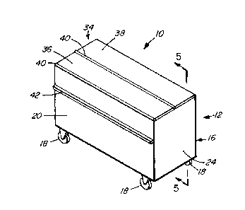
[0013] Fig. 1 is a front perspective view of an embodiment of the mobile
electronic display
apparatus configured with the display in a stowed position and the cover
closed.
[0014] Fig. 2 is a side elevational view of the apparatus of Fig. 1 with the
cover partially opened.
[0015] Fig. 3 is a side elevational view of the apparatus of Fig. lwith the
cover further partially
opened.
[0016] Fig. 4 is a side elevational view of the apparatus of Fig. 1 with the
cover fully opened.
CA 02916514 2015-12-30
-4-
[0017] Fig. 5 is a sectional view of the apparatus of Fig. 1 taken along
section lines 5-5 of Fig. 1
showing the display in the stowed position in solid lines and in an extended
position in dashed
lines.
[0018] Fig. 6 is a front perspective view of the apparatus of Fig. 1 with the
cover fully opened
and the display adjusted to an extended position, showing the display in a
vertical orientation.
[0019] Fig. 7 is a rear perspective view of the apparatus of Fig. 6 showing
the display in an
inclined orientation.
[0020] Fig. 8 is a front perspective view of the apparatus of Fig. 6 showing
the display in a
horizontal orientation.
[0021] Fig. 9 is a front perspective view of another embodiment of the mobile
electronic display
apparatus configured with the display in a stowed position and the cover
closed.
[0022] Fig. 10 a rear perspective view of the apparatus of Fig. 9.
[0023] Fig. 11 is a sectional view of the apparatus of Fig. 9 taken along
section lines 11-11 of
Fig. 9 showing the display in the stowed position in solid lines and in an
extended position with
the cover open in dashed lines.
[0024] Fig. 12 is an enlarged front perspective view of an upper portion of
the apparatus of Fig.
9 showing the display in a stowed position shown in solid lines and partially
adjusted to an
extended position shown in dashed lines.
[0025] Fig. 13 is a front perspective view of the apparatus of Fig. 12 showing
the display
adjusted to a further extended position.
[0026] Fig. 14 is a rear perspective view of the apparatus of Fig. 13.
CA 02916514 2015-12-30
-5-
Description
[0027] Throughout the following description specific details are set forth in
order to provide a
more thorough understanding to persons skilled in the art. However, well known
elements may
not have been shown or described in detail to avoid unnecessarily obscuring
the disclosure.
Accordingly, the description and drawings are to be regarded in an
illustrative, rather than a
restrictive, sense.
[0028] This application relates to a mobile electronic display apparatus
generally designated 10.
Apparatus 10 includes a cabinet 12 for receiving and supporting a display 14.
In some
embodiments display 14 may be a flat panel LCD screen. In other embodiments
display 14 may
be any visual interface device suitable for electronically displaying viewable
content, such as
building plans and the like.
[0029] In the illustrated embodiments cabinet 12 includes a housing 16 and a
plurality of wheels
18 for enabling rolling movement of cabinet 12 over a support surface. In some
embodiments
housing 16 includes a front panel 20, a rear panel 22, first and second spaced-
apart side panels
24, a top panel 26 and a bottom panel 28. Panels 20-28 together defined an
enclosure 30 within
the interior of housing 16 for receiving display 14 as discussed below. In one
embodiment
panels 20-28 may be constructed from aluminum, e.g. 10 gauge aluminum. Wheels
18 may be
mounted in corner sections of bottom panel 28 and may comprise swivels and
brakes/locks.
[0030] As shown in the drawings, display 14 is adjustable between a stowed
position received
within enclosure 30 (shown in solid lines in Fig. 5) and an extended position
at least partially
removed from enclosure 30 (shown in dashed lines in Fig. 5 and in Figs. 6-8).
In one
embodiment apparatus 10 may include a counterbalance (not shown) to aid in
manually raising
display 14 from the stowed to the extended positions. An opening 32 may be
formed in an upper
portion of housing 16 to permit movement of display 14 between the stowed and
extended
positions. For example, the opening 32 may be a slot formed in top panel 26.
As shown in Figs.
1-5, a separate cover 34 may be provided for adjustably covering top panel 26.
Cover 34 may
CA 02916514 2015-12-30
-6-
comprise a first panel 36 and a second panel 38 connected by a hinge 40. First
cover panel 36
may be coupled to front panel 20 of housing 16 by means of a hinge 40. In one
embodiment
cover 34 may be adjusted between closed and open positions as shown in Figs. 2-
4. In the open
position an edge of cover panel 38 may be supported on a rib 42 projecting
from front panel 20.
[0031] In an alternative embodiment (not shown) cover 34 may be omitted and
top panel 26 may
be adjustable between a closed position covering opening 32 and an open
position exposing
opening 32. For example, top panel 26 may be foldable between the closed and
open positions.
[0032] In one embodiment display 14 is securely lockable within enclosure 30
when display 14
is in the stowed position and cover 34 and/or top panel 26 is in the closed
position.
[0033] As best shown in Figs. 5 and 7, apparatus 10 also includes a support 44
for adjustably
coupling display 14 to housing 16. In one embodiment support 44 includes a
pair of spaced-
apart support rails 46 extending within enclosure 30. For example, rails 46
may be mounted to a
support structure 48 within enclosure 30 (Fig. 5). In other embodiments rails
46 could be
mounted to an inner surface of front panel 20 or rear panel 22.
[0034] In one embodiment support 44 further includes a support panel 50 which
is slidably
movable relative to rails 46. For example, elongated ribs 52 may be mounted on
support panel
50 for sliding in rails 46 (Fig. 7). In one embodiment a mounting plate 54 may
be mounted on a
rear portion of display 14 for pivotably coupling display 14 to support panel
50. For example,
mounting plate 54 may be coupled to support panel 50 by means of a hinge 56
(Fig. 5 and 7).
[0035] Support 44 supports sliding movement of display 14 between a stowed
position within
enclosure 30 and an extended position at least partially removed from
enclosure 30. In the
extended position, display 14 is pivotable relative to support panel 50 to
adjust the orientation of
display 14. For example, in the extended position display 14 is selectively
pivotable between a
vertical orientation (Fig. 6), a partially inclined position (Fig. 7) and a
horizontal orientation (Fig.
CA 02916514 2015-12-30
-7-
8). In one embodiment support 44 may include a locking means for locking
display 14 in the
desired orientation.
[0036] Figs. 9-14 illustrate another embodiment of apparatus 10. In this
embodiment cover 34
comprises a single panel 36 which is coupled to top panel 26 by means of a
hinge 40. In the
illustrated embodiment top panel 26 may comprise a slightly inclined forward
portion and a rear
portion disposed at a slightly lower elevation so that cover 34 rests flush
with the forward portion
of top panel 26 when cover 34 is closed (Figs. 9-10). Alternatively, the
forward and rear
portions of top panel 26 could be flush and cover panel 36 could overlie top
panel 26.
[0037] As shown best in Figs. 11-14 a slot may be formed in a rear portion of
top panel 26 to
form opening 32. As in the embodiment described above, this permits adjustment
of display 14
between stowed and extended positions. In the embodiment of Figs. 9-14,
support 44 for
supporting display 14 for movement between the stowed and extended positions
comprises an
automatic lift mechanism. For example, a suitable lift mechanism is an
automatic television lift
mechanism sold by Firgelli Automations of Ferndale, Washington. More
particularly, support
44 may comprise a lifting column 60 which is mounted on mounting brackets 62
secured to a
rear surface of display 14. Column 60 may comprise telescoping segments 60A
and 60B (Fig.
11). A wheel assembly 64 is mounted on an upper surface of lifting column 60.
When lifting
column 60 is raised, wheel assembly 64 contacts an undersurface of cover panel
36 and raises
cover 34 from a substantially horizontal closed position (Figs. 9-10) to a
substantially vertical
raised position (Figs. 12-14). Opening 32 may include a cut-out portion for
accommodating
lifting column 60 as it is raised and lowered. As shown best in Fig. 11,
lifting column 60 may be
secured within the interior of enclosure 30 on or near rear panel 22.
[0038] As will be apparent to a person skilled in the art, support 44 may be
actuated by a
cabinet-mounted control and/or a remote control to automatically raise and
lower display 14
between the stowed and extended positions. In the embodiment illustrated in
Figs. 12-14,
display 14 is deployed in a vertical orientation in the extended position.
However, in alternative
CA 02916514 2015-12-30
-8-
embodiments support 44 may be adapted to additionally or alternatively deploy
display 14 in
inclined and/or horizontal orientations.
[0039] As shown in Fig. 10, cabinet 12 may include a door 70 formed in rear
panel 22 for
gaining access to enclosure 30. A handle 72 may be provided for opening and
closing door 70.
In other embodiments door 70 could be formed in front panel 20 or another
panel of housing 16.
[0040] In some embodiments display 14 may comprise a touch-screen panel.
Display 14 may be
operatively coupled to electronic equipment 74 positioned within enclosure 30
(Fig. 11). As will
be apparent to a person skilled in the art, many types of local or remote
electronic equipment
could be employed for communicating with and/or controlling operation of
display 14. For
example, in some embodiments equipment 74 could comprise a computer processor,
modem,
router and/or other electronic device located within enclosure 30 or elsewhere
and connected to
display 14 with wired connectors or by means of a wireless connection. In some
embodiments
apparatus 10 could include other equipment housed within enclosure 30, such as
a GPS tracking
device for monitoring and tracking the location of apparatus 10.
[0041] Cabinet 12 preferably has a relatively narrow profile so it can easily
traverse through
standard size doorways, hallways, into elevators etc. In one particular
embodiment cabinet 12
has a width less than approximately 32 inches (approximately 80 cm). Wheels 18
allow rolling
movement of cabinet 12 over different terrain. Wheels 18 may be lockable for
immobilizing
cabinet 12 at a desired location.
[0042] In operation, apparatus 10 may be used, for example, at a construction
site. Cabinet 12
may be rolled to the desired location at the site with display 14 in the
stowed position within
enclosure 30 and with cover 34 closed. Wheels 18 may then be locked to
immobilize apparatus
at the desired location. A user could then open cover 34 as described above to
expose
opening 32. Next, the user could adjust display 14 from the stowed position to
the extended
position removed from housing 16. Depending upon the particular application
and user
preference, display 14 may be deployed in different orientations in the
extended position, such as
CA 02916514 2015-12-30
-9-
a vertical orientation, a partially inclined orientation and/or a horizontal
orientation (Figs. 6-8).
In one embodiment display 14 may be used to electronically display
construction
plans/blueprints and the like. This would enable workers to consult display 14
at the
construction site to review plans, renderings, photographs models and the like
rather than
conventional printed blueprints. As mentioned above, display 14 could include
touch screen or
other interactive functionalities. For example, display 14 could receive input
in real time from
designers or architects working at remote locations. By way of a specific
example, designers or
architects, or construction workers on-site, could read, mark-up and transmit
construction
drawings electronically to speed-up and streamline the drawing revision
process. This would
permit the drawings to be updated and transmitted directly to the work site,
thereby avoiding the
need to print updated blueprints and enabling real-time collaboration between
a work site and a
head office. By way of another example, safety or material handling
information could be
transmitted to display 14 for convenient review and acknowledgement by workers
on-site.
[0043] At the end of the construction day, or when display 14 is otherwise not
in use, display 14
may be adjusted from the extended to the stowed position as described above.
Optionally, cover
34 may be closed and display 14 may be securely locked within enclosure 30.
When display 14
is stowed and cabinet 12 is locked as aforesaid display 14 is protected from
dust, debris or other
potentially harmful conditions at the construction site. Also, display 14 and
any other related
electronic equipment such as computer processors is protected from theft.
[00441 At the end of the construction project, apparatus 10 may be easily
moved to another
construction site or other desired location. The user would simply unlock the
wheels 18 and roll
cabinet 12 to a transport vehicle or directly to a new site.
[0045] While a number of exemplary aspects and embodiments have been discussed
above,
those of skill in the art will recognize certain modifications, permutations,
additions and sub-
combinations thereof. It is therefore intended that the following appended
claims and claims
hereafter introduced are interpreted to include all such modifications,
permutations, additions
and sub-combinations as are within their true spirit and scope.