Note : Les descriptions sont présentées dans la langue officielle dans laquelle elles ont été soumises.
CA 02916756 2015-12-23
WO 2015/000490
PCT/DK2014/050202
1
A CORNER BRACKET, A BRACKET SYSTEM, USE OF SUCH A CORNER
BRACKET, A WINDOW MOUNTING COLLAR AND A WINDOW MOUNTING
SYSTEM
This invention relates in a first aspect to a corner bracket for assembly
of two boards of a window mounting collar into a collar corner and for
affixing
said window mounting collar to an exterior face of a building façade so as to
surround a window opening. The invention also relates in a second aspect to
a bracket set comprising a corner bracket, in a third aspect to use of a
corner
bracket, in a third aspect to a window mounting collar, and in a fourth aspect
to a window mounting system.
When building façades are insulated with external wall insulation, the
window frames of the building can act as a thermal bridge, because the win-
dow frames are generally not covered by the external wall insulation. Heat
can, therefore, escape from the building by passing from the building interior
through the building wall, into the window frame and to the exterior of the
building. Such thermal bridges can undermine the benefit of the new insula-
tion.
In order to reduce the thermal bridging effect of the window frames,
the windows are often replaced when the external wall insulation is installed.
The new windows are often shifted outwards and arranged so that they are in
line with the new façade front. This reduces thermal bridging by preventing
contact between the window frame and the building wall itself.
However, in order to fix the new windows in place securely, in particu-
lar so that the building meets fire regulations, it is often necessary to fix
the
window in its new position with brackets, which are attached to the window
frame at one end and the reveal or window opening in the building wall at the
other. In order to provide sufficient support for the window frame, these
brackets must be very strong. They are, therefore, generally metal brackets
which form a thermal bridge between the window frame and the building
wall. Furthermore, since the brackets are attached to the reveal of the build-
ing wall, it is necessary to remove the existing window frame before
installing
the new window frame. This is undesirable, because it leaves the building
open to the elements for a period of time. That is particularly problematic
CA 02916756 2015-12-23
WO 2015/000490
PCT/DK2014/050202
2
when the building remains occupied during the installation process, as is of-
ten the case.
DE 20 2008 016 538 U1 discloses an assembly for installation into an
opening in a building wall, which includes a facing frame, made from ther-
mally insulating material, which is secured to a frame arranged in the open-
ing of the building wall. The window frame is mounted within the insulating
frame.
The insulating frame is attached to the frame arranged in the opening
of the building wall. There is also no separation between the plane of the
face
of the building façade and the window frame. These features make installa-
tion of a new window impossible before the existing window is removed.
DE 20 2006 000 4425 describes a frame assembly for sealing a build-
ing opening such as a window or door, which comprises a prefabricated insu-
lation system that is integrally joined to a window frame. Brackets are used
to fix the window frame itself to the building wall. In this system, the
window
frame is attached directly to the building wall. Therefore, although
installation
is quick, a thermal bridge is formed. This system also appears to prevent in-
stallation of a new window before the existing window has been removed.
DE 299 05 365 U1 describes a prefabricated thermal insulating ele-
ment to be placed in the opening in a façade-insulating layer that is aligned
with an opening in the building wall. The prefabricated element has a reveal
element formed from a thermal insulating material that is attached to a win-
dow frame. When the prefabricated element is installed, the window frame
sits within the opening of the building wall. This positioning of the window
frame makes it impossible to install the prefabricated element before any ex-
isting window has been removed.
On the above background the present invention relates in a first aspect
to a corner bracket for assembly of two boards of a window mounting collar
into a collar corner and for affixing said window mounting collar to an
exterior
face of a building façade so as to surround a window opening.
Assembly and mounting of the above described window mounting col-
lar on an exterior face of a building façade presents a number of challenges.
First, it is desirable to be able to attach the boards to each other to form
the
collar, either before or during affixing of the collar to the exterior face of
the
building façade. Further, affixation should be sufficiently strong, and
affixing
CA 02916756 2015-12-23
WO 2015/000490
PCT/DK2014/050202
3
of the boards to each other should preferably be independent from the spe-
cific material of the boards, for example from whether it is possible to
attach
screws to the boards. For example man-made vitreous fibre boards, e.g.
mineral wool fibre boards, will not always be able to provide satisfactory af-
fixation of e.g. screws screwed into the boards. Moreover, freedom regarding
spacial dimensions of the boards is of value to make in situ adjustment of the
dimensions possible. Finally, insulation abilities of the resultant
construction
are of importance.
In view of the above the object of the present invention is providing a
solution for cheap and effective assembly of a window mounting collar and
mounting of this on an exterior face of a building façade.
With the first aspect of the invention this object is met by providing a
corner bracket comprising:
two holding plates and two base arms, all four adapted for extending
in planes parallel with and having back surfaces abutting the exterior face of
the building façade in an affixed position of the collar, the two base arms
each being adapted for receiving a fixation member for insertion there-
through and into the building façade such as to fixate the collar to the fa-
çade;
a flange arm comprising two flanges adapted to extend away from
said exterior face in the affixed position of the collar, each flange having a
proximal end configured to be proximal and a distal end configured to be dis-
tal to the exterior face in the affixed position of the collar, each flange
further
having an attaching edge extending from the proximal end to the distal end,
the attaching edges of the flanges being attached to each other along at least
a part of the attaching edges, the flanges extending at a mutual angle such
as to form a flange corner at said attaching edges, the flange corner being
adapted to be positioned in an inner corner formed between the two boards
in the affixed position of the collar;
two abutment plates adapted to extend away from said exterior face
in the affixed position of the collar, each abutment plate having a proximal
end configured to be proximal and a distal end configured to be distal to the
exterior face in the affixed position of the collar, each abutment plate being
adapted to abut a respective outer surface of the two boards in the affixed
position of the collar; and
CA 02916756 2015-12-23
WO 2015/000490 PCT/DK2014/050202
4
each abutment plate being positioned at a mutual distance from and
in parallel with an associated said flange, each abutment plate being con-
nected to the associated said flange via an associated said holding plate;
so as to be able to hold said boards together to form said window col-
lar corner, each board being received between a respective flange and its
associated abutment plate.
Thus, according to the first aspect of the invention two boards of a
window mounting collar may be brought together and preliminarily retained
in a collar corner of the collar between the respective associated abutment
plates and flanges of the corner bracket. This reduces work time and provides
for easier and quicker assembly of the boards. In this context it is possible
to
provide pretension in the corner bracket material at one or more of the distal
ends of the abutment plates and flanges, forcing the abutment plate and as-
sociated flange towards each other for better preliminary attachment. Such
pretension can in principle be strong enough to provide permanent retention
of the boards.
After preliminarily retaining the boards between the plates and the as-
sociated flanges, the boards may then be permanently attached to each other
by a separate attachment means such as a screw or bolt inserted through the
respective associated flanges and plates and through the associated board.
Hereby, the attachment means need not be able to firmly grip the material of
the boards since the respective associated abutment plates and flanges will
be able to retain the boards to the corner bracket by means of pressure ex-
erted on the board by means of for example a bolt head on the one side of
the board and an associated nut on the other side.
Mutual attachment of the flanges along the attaching edges provides
increased rigidity of the corner bracket in the direction of the flange
planes.
This is important to ensure that the corner bracket is strong enough to with-
stand forces not only from gravity of collar, window and/or insulation plates
positioned around the collar, but especially also from wind forces acting on
the collar after mounting thereof. Also, the attaching edges provide an inner
flange corner, which enables or improves guided abutment of the boards
against this corner.
Since the corner bracket need not be attached to or be in contact with
the boards at or near the outer surface, i.e. the surface of the boards posi-
CA 02916756 2015-12-23
WO 2015/000490 PCT/DK2014/050202
tioned co-planarly with and at a distance from the façade, it is possible to
reduce thermal bridging between the façade and the outside.
In an embodiment of the first aspect of the invention said two abut-
ment plates of the corner bracket are positioned at a distance from each
5 other. Preferably, each abutment plate does not extend beyond a plane in
which its non-associated flange extends.
In the first aspect of the invention the flanges are directly attached to
each other. Thereby, it is not necessary for the abutment plates to be at-
tached to each other for the corner bracket to be held together. The distance
between the two abutment plates of the corner bracket enables the corner
bracket to be manufactured as one integral piece by punching it out from a
single sheet of plate metal (or like material), thereby avoiding a time-
consuming assembly process of several parts to form the corner bracket. Ac-
cordingly, in a preferred embodiment the corner bracket is obtainable by a
process of punching one single work-piece out from a single sheet of plate
metal and folding or bending the work-piece into shape. It should be noted
that it is alternatively possible to for example cast or mould the bracket in
one integral piece to avoid assembly of the bracket. To this end the corner
bracket may be manufactured from metal or a plastic material.
In another embodiment said two flanges of the corner bracket extend
in respective planes forming a mutual angle of 60 - 1200, preferably 80 -
1000, more preferred approximately 900, and/or said two abutment plates
extend in respective planes forming a mutual angle of 60 - 1200, preferably
80 - 1000, more preferred approximately 900, and/or each associated abut-
ment plate and flange extend in parallel planes. Furthermore, each associated
holding plate and flange extend in respective planes forming a mutual angle
between approximately 60 - 1200, preferably 80-1000, more preferred ap-
proximately 900, and/or each associated holding plate and abutment plate
extend in respective planes forming a mutual angle between approximately
60 - 1200, preferably 80-1000, more preferred approximately 900. By provid-
ing the corner bracket with angle dimensions close to right angles, an ap-
proximately rectangular window mounting collar may be provided that may
be attached to the exterior face of a plane building façade, surrounding a
window, such that a regular rectangular window frame can be positioned in-
side said collar. However, the corner bracket may be configured to match
CA 02916756 2015-12-23
WO 2015/000490
PCT/DK2014/050202
6
windows, collars or facades of other shapes and sizes, such as triangular win-
dows and collars, where the angles may be 600 or less, or pentagonal win-
dows and collars, where the angles may be larger than 900.
In another embodiment each of said base arms are formed as an ex-
tension of the associated said holding plate, each base arm extending away
from a plane of the associated said abutment plate so that the associated
fixation member can be inserted through the base arm when the two boards
are positioned to be held between the respective flanges and abutment
plates, and/or at least one of said base arms comprises a receiving aperture
for receiving the fixation member therethrough. By providing the corner
bracket with base arms as described above it is possible to affix the corner
bracket to the exterior face of the building façade, both with or without the
two boards positioned between the respective flanges and abutment plates,
thus facilitating the possibility of providing collars already assembled with
corner brackets mounted to the boards at each corner of the collar, ready for
affixing on the exterior face at delivery. Furthermore, the corner bracket may
be attached to the exterior face of the building facade to achieve the advan-
tages therewith as explained above.
Each base arm and each associated abutment plate or associated
flange may extend in respective planes forming a mutual angle between ap-
proximately 60 - 1200, preferably 80-1000, more preferred approximately
900. With angle dimensions as described above, an approximately plane back
surface of the corner bracket is provided, which may be adapted to abut a
plane of the exterior face, such as to create greater stability and strength.
In another embodiment each of said base arms is obtainable by punch-
ing it out from an associated one of said abutment plates and folding or
bending it into position. This makes it possible to manufacture the base arms
integral with the associated abutment plates, thereby avoiding time-
consuming assembly of several parts.
In another embodiment at least one of each associated abutment plate
and flange comprises at least one retention aperture positioned for receiving
a preferably oblong retention member, such as a screw or a bolt, inserted
through the associated abutment plate, through the board to be positioned
between the associated abutment plate and flange, and through the associ-
ated flange so as to press the board in between the associated abutment
CA 02916756 2015-12-23
WO 2015/000490
PCT/DK2014/050202
7
plate and flange to retain the board, the abutment plate and flange being
pulled against each other by means of the retention member. The screw or
bolt may at one end comprise a head with a nut or the like screwed upon the
opposite end of the screw or bolt such as to provide oppositely directed
forces
by the head and the nut, respectively, on each side of the board to be re-
tained between the respective flange and associated abutment plate. The at
least one retention aperture may be one or more slots or holes, preferably
with several apertures positioned to make it easier to match retention mem-
ber with retention aperture at an end of the retention member first inserted
into the retention aperture, i.e. when the retention member comes out of the
board on the opposite side of the board. By pressing the board in between
the associated abutment plate and flange to retain the board by means of the
retention member the respective associated abutment plates and flanges will
be able to retain each of the two boards to the corner bracket independent of
whether or not the specific material of the boards allows for firm attachment
of the retention member, such as a screw, to the board itself. This allows for
use of for example boards manufactured from man-made vitreous fibre, e.g.
mineral wool fibre, with the associated advantages thereof.
However, if the boards are formed from material in which it is possible
to sufficiently firmly attach screws or like retention members, it may also be
possible to affix the boards to the bracket corner by inserting the retention
member such that it does not extend fully through the board, thereby not
connecting the associated abutment plate and flange.
In an embodiment of the first aspect of the invention the corner
bracket further comprises two boards of a window mounting collar assembled
to form a collar corner by means of the corner bracket, said two boards being
held together by the corner bracket to form said collar corner, each board
being received between a respective flange and its associated abutment
plate, wherein each board has an outer board surface, which is adapted to be
parallel with and to face away from the exterior face of the façade in the af-
fixed position of the collar, each flange and associated abutment plate being
in contact with an associated one of said two boards, the distal end of each
flange and/or of each abutment plate being positioned at a distance from the
outer board surface of its associated board of 10% to 150%, preferably 25%
to 75 %, more preferred approximately 50 %, of a length of the respective
CA 02916756 2015-12-23
WO 2015/000490
PCT/DK2014/050202
8
flange or abutment plate. This distance between the distal end of the flanges
and abutment plates from the outer board surface minimizes the corner
bracket's thermal bridging between the surroundings and the exterior face of
the façade.
In the second aspect of the present invention the above object is met
by providing a bracket set, which comprises a corner bracket according to the
first aspect of the invention as well as one or two further, different
brackets.
By providing different bracket types, where each bracket is formed from the
same base bracket shape, a more cost-effective and simple production is fa-
cilitated. Each bracket may for example be punched out in the same pattern
from a sheet of plate metal after which further punching or different folding
procedure may result in the different brackets. Each bracket of the bracket
set may thus be produced in very much the same process, thereby to a large
extent avoiding different process steps.
Furthermore, by providing the bracket set, it is possible to not only as-
semble the collar by using the corner brackets, but also to provide additional
support and rigidity along the boards. The joining bracket also provides for
the possibility of assembling two boards at their respective ends along a side
of the mounting collar, thereby making it possible to use more of the board
material when the boards are provided in standard lengths. This material
would otherwise need to be disposed of.
In the third aspect of the invention the above object is met by provid-
ing use of a corner bracket according to the first aspect of the invention for
holding together two boards of a window mounting collar to form a window
mounting collar corner, each board being received between a respective
flange and its associated abutment plate and attached by means of a pref-
erably oblong retention member inserted through the respective flange, the
respective board and the abutment plate associated with said respective
flange, and further for affixing said window mounting collar to an exterior
face of a building façade so as to surround a window opening, the two base
arms each receiving a preferably oblong fixation member for insertion there-
through and into the building façade such as to fixate the window mounting
collar to the façade.
Such use simplifies both collar assembly and mounting process as the
collar assembly can be combined with the process of affixing the boards of
CA 02916756 2015-12-23
WO 2015/000490
PCT/DK2014/050202
9
the collar to the corner bracket. This can be done both prior to, during or af-
ter the corner bracket is affixed to the exterior face of the building façade.
In the fourth aspect of the invention the above object is met by pro-
viding a window mounting collar having at least one inside face, at least one
outside face, a first open end and a second open end and comprising a corner
bracket according to the first aspect of the invention.
This window mounting collar may be affixed to the exterior face to sur-
round a window and may be adapted to receive the window through the first
or second open end, the window further being received by the at least one
inside face of the collar.
The window mounting collar may be made using boards of any suitable
material, such as plywood, cement or similar common building materials.
However according to an embodiment at least one of the boards comprises or
is manufactured from man-made vitreous fibre material. Such boards have a
number of advantages in this context, such as resistance to deterioration
from rot, fungus etc, superior fire rating, superior thermal conductivity, and
relatively low weight.
In the fifth aspect of the present invention the above object is met by
providing a window mounting system comprising a building façade having an
interior face and an exterior face and comprising a window opening and a
window mounting collar according to the fourth aspect of the invention, the
window mounting collar preferably comprising two side boards, an upper
cross board and a lower cross board, each having an inside face and an out-
side face, wherein at least one and preferably each side board is joined or-
thogonally to the upper and lower cross boards by means of a corner bracket
according to the first aspect of the invention.
Since the collar is affixed directly to the exterior face opposed to the
inside of the window opening, the process of moving the window from an
original position to a position in the collar, may be performed without first
having to remove the window to attach the collar, thereby providing for a
quicker and easier assembly, see also the remarks described above in the
disclosure of the background of the present invention.
The invention is described further below with reference to the Figures,
where Figures 1 to 4b are not according to the invention.
Figure 1 shows a first window mounting collar.
CA 02916756 2015-12-23
WO 2015/000490
PCT/DK2014/050202
Figure 2 shows a first window mounting system.
Figure 3 shows a section through the system of Figure 1, viewed from
above.
Figures 4a and 4b show a bracket system from two angles.
5 Figure 5 shows a second window mounting collar, which is according to
the fourth aspect of the present invention.
Figure 6a shows a perspective view of an embodiment of the corner
bracket according to the first aspect of the invention.
Figure 6b shows a first side view of the corner bracket shown in Figure
10 6a.
Figure 6c shows a second side view of the corner bracket shown in
Figure 6a.
Figure 7 shows a top view of a work-piece punched out from one single
sheet of plate metal, the work-piece being adapted to be folded or bent into
the corner bracket of Figure 6a.
Figure 8 shows a perspective view of a holding bracket according to
the bracket set of the second aspect of the invention.
Figure 9 shows a perspective view of a joining bracket according to the
bracket set of the second aspect of the invention.
Figure 10 shows a means by which a window frame can be arranged in
a window mounting collar.
In Figure 1, a window mounting collar 1 is shown before installation on
a building façade. The mounting collar 1 comprises two side boards 2, an up-
per cross board 3 and a lower cross board 4, each having an inside face 2a,
3a, 4a and an outside face 2b, 3b, 4b, wherein each side board 2 is joined
orthogonally to the upper and lower cross boards 3, 4. The mounting collar
has a first open end 5, which, when installed, faces the exterior face of the
building façade. The second open end 6 of the mounting collar 1 receives a
window frame, which can be installed either before the mounting collar is af-
fixed to the building façade or after the mounting collar has been affixed to
the building façade.
In the embodiment shown, the two side boards 2, the upper cross
board 3 and the lower cross board 4 are each formed from three layers of
man-made vitreous fibre boards, each layer comprising man-made vitreous
fibres and binder.
CA 02916756 2015-12-23
WO 2015/000490
PCT/DK2014/050202
11
Preferably, each board has a bending strength of at least 7 N/m2 and
a point load resistance of at least 500 kN.
The board preferably has a thermal conductivity, measured in a direc-
tion from the first end to the second of the collar, of below 0.150 W/m.K,
preferably below 0.100 W/m.K. The thermal conductivity of the board, meas-
ured in a direction from its inside face to its outside face, is preferably
below
0.150 W/m.K, more preferably below 0.100 W/m.K. The thermal conductivity
of the board, measured in a direction from its inside face to its outside
face,
is often lower than the thermal conductivity, measured in a direction from the
first end to the second of the collar. Most preferably, the thermal
conductivity
of the board, measured in a direction from its inside face to its outside
face,
is below 0.075 W/m.K.
In one embodiment, the board comprises man-made vitreous fibres
and binder and has a density of at least 150 kg/m3. Such compressed man-
made vitreous fibre boards generally have sufficient rigidity and strength to
support window frames without the use of additional brackets attaching the
window frame to the building façade directly. It is preferred that the
material
has a density of at least 200 or at least 300 kg/m3. Usually, the density is
less than 600 kg/m3, preferably less than 500 kg/m3.
Particularly suitable man-made vitreous fibre boards are produced ac-
cording to the method described in W02011/012712. Preferably, the boards
comprise from 1% to 20% binder and from 80 to 99% man-made vitreous
fibres.
Compressed man-made vitreous fibre boards have the additional bene-
fit that they are fire-proof. In a preferred embodiment, the man-made vitre-
ous fibre boards are layered to form the sides of the mounting collar. Where
at least two man-made vitreous fibre boards are layered at their large sur-
faces, the bending strength of the mounting frame can be improved, thereby
improving the stability of the system.
Alternatively, the mounting collar can be formed from polymeric foam,
for example polyurethane foam.
In a further embodiment, the mounting collar is formed from a poly-
meric foam composite material comprising a polymeric foam and man-made
vitreous fibres, wherein at least 50% by weight of the man-made vitreous
fibres present in the polymeric foam composite material have a length less
CA 02916756 2015-12-23
WO 2015/000490
PCT/DK2014/050202
12
than 100 micrometers. Such a polymeric foam composite is discussed in our
co-pending application PCT/EP2012/066196.
Attached to the mounting collar 1, on its outside faces 2b, 3b, 4b, are
brackets 7. In the embodiment shown, the brackets 7 are L-shaped brackets,
which are positioned on the outside faces of the mounting collar adjacent to
its first open end 5.
Figure 2 shows the mounting collar 1 in place on a building façade 8,
as part of a complete window mounting system. Brackets 7 affix the mount-
ing collar 1 to the exterior face of the building façade 8. A window frame 9
is
mounted in the mounting collar such that there is a separation d shown in
Figure 3 of at least lOmm between the window frame 9 and the plane of the
exterior face of the building façade 8. The window frame 9 surrounds a win-
dow sash 10 and window panes 11. External wall insulation 12 not shown on
one side of the mounting collar is positioned around the outside of the
mounting collar 1 and affixed to the building façade 8. The external wall insu-
lation 12 has the same depth as the mounting collar 1, so the window frame
9 is arranged to be flush with the outer surface of the external wall
insulation
12.
Figure 3 shows a section through the system of Figure 2, viewed from
above. The side boards 2 of the mounting collar 1 are affixed to the exterior
face 13 of the building façade 8. The side boards 2 extend perpendicularly
outwards from the building façade 8. L-shaped brackets 7 have two perpen-
dicular arms, one of which is attached to an outside face 2b of the mounting
collar 1, the other of which is attached to the exterior face 13 of the
building
façade 8. The separation d between the window frame 9 and the plane of the
exterior face 13 of the façade allows the mounting collar 1 to be fitted when
an existing window is still present in the window opening 14. External wall
insulation 12 is present on either side of the mounting frame 1. The mounting
collar 1 extends away from the building façade 8 by the same distance as the
depth of the external wall insulation 12. Means for attaching the window
frame 9 to the mounting collar 1 are not shown, but could, for example, be
screws passing through the window frame 9 and into the mounting collar 1.
Figures 4a and 4b show a corner system that may be used with the
window mounting collar 1 according to figure 1 and comprising two boards la
and lb of the window mounting collar 1 assembled to form a collar corner by
CA 02916756 2015-12-23
WO 2015/000490
PCT/DK2014/050202
13
means of a corner bracket denoted 0. The window mounting collar could be in
the form of that shown in Figure 1. The corner bracket 0 comprises a bracket
part 15 with two base arms 16 in the form of plates and flange arm 17, which
comprises two abutment plates 17a, 17b that are substantially perpendicular
to each other and are joined at one edge. The two abutment plates 17a, 17b
extend away from the exterior face of the facade 8 in the affixed position of
the collar 1. Each abutment plate 17a, 17b has an end proximal and an end
distal to the exterior face of the facade 8 in the affixed position of the
collar
1. Each abutment plate 17a, 17b abuts a respective outer surface of the two
boards la, lb. In the embodiment of Figures 4a and 4b the two abutment
plates 17a, 17b are attached to each other along a mutual attachment edge.
The two base arms 16 extend in planes parallel with the exterior face
of the building façade in the affixed position of the collar 1. The two base
arms 16 further have back surfaces for abutting the exterior face and are
each provided with five fixation member holes or receiving apertures 18 for
receiving fixation members (not shown), such as screws, therethrough and
into the building façade such as to fixate the collar 1 to the façade. The sec-
ond arm 17 of the bracket part 15 extends away from the exterior face of the
building façade 8 along two of the outside faces 2b, 3b of the boards la, lb,
respectively, of the mounting collar 1.
Holding part 19 has an attachment arm 20 and two holding plates 21a,
21b formed as two connected parts of one single plate positioned at an outer
surface of the two boards la, lb. The holding plates 21a, 21b extend in
planes parallel with and are positioned at a distance from the exterior face
of
the building façade 8 in the affixed position of the collar 1. The attachment
arm 20 is in the form of two substantially orthogonal plates 20a, 20b, at-
tached to each other at one edge, and each attached to the holding plate 21
at one end. The holding plate 21 is L-shaped to match the shape of the cor-
ner of the mounting collar 1 and has two flanges 22 that are perpendicular to
each other and perpendicular to the holding plate 21. The flanges 22 extend
away from the exterior face of the facade 8 in the affixed position of the col-
lar 1 to be attached to respective edges of the holding plates 21a, 21b posi-
tioned opposite to the edges attached to the plates 20a, 20b of the attach-
ment arm 20. The flanges 22 lie against two adjoining inside faces 2a, 3a of
the respective boards la, lb of the mounting collar 1. Each flange 22 has an
CA 02916756 2015-12-23
WO 2015/000490
PCT/DK2014/050202
14
end proximal to and an end distal to the exterior face of the facade 8 in the
affixed position of the collar 1. The flanges 22 extend at a mutual angle of
about 900 such as to fit snugly into an inner corner formed between the two
boards la, lb.
Each abutment plate 17a, 17b is positioned at a mutual distance from
and in parallel with an associated of the two flanges 22. This distance is es-
tablished as corresponding to the thickness of the boards la, lb since the
associated flange 22 and abutment plate 17a, 17b are positioned on each
side of the respective board la, lb. Each abutment plate 17a, 17b is con-
nected to the associated of the flanges 22 via an associated of the holding
plates 21b, 21a, respectively. Each abutment plate 17a, 17b extends in this
embodiment beyond a plane in which its non-associated flange 22 extends;
for example, the abutment plate 17a extends farther in the left direction of
Figure 4a than to the plane in which the lowermost flange (which abuts the
holding plate 21a) extends. The plane, in which the lowermost flange (which
abuts the holding plate 21a) extends, extends along the inside face 2a of
board la. Each associated abutment plate 17a, 17b and flange 22 extend in
parallel planes. Each of the base arms 16 are positioned at a distance from
the associated holding plate 17a, 17b.
Hereby, the two boards la, lb are held together by the corner bracket
0 to form the window collar corner, each board la, lb being received be-
tween a flange 21a, 21b and its associated abutment plate 17b, 17a, respec-
tively.
Since the holding plates 21a, 21b are attached along outer edges to
the plates 20a, 20b, respectively, the corner bracket is in this embodiment
not directly obtainable by a process of punching one single work-piece out
from a single sheet of plate metal and folding or bending the work-piece into
shape.
In the corner bracket shown in Figures 4a and 4b the two flanges 22
extend in respective planes forming an angle between them of approximately
900, and the two abutment plates 17a, 17b extend in respective planes form-
ing a mutual angle of 900. Each associated holding plate 21a, 21b and flange
22 extend in respective planes forming an angle of approximately 900, and
each associated holding plate 21a, 21b and abutment plate 17b, 17a, respec-
tively, extend in respective planes forming an angle of approximately 900.
CA 02916756 2015-12-23
WO 2015/000490
PCT/DK2014/050202
The abutment plates 17a, 17b each comprises a slit extending along
the respective abutment plates 17a, 17b for receiving screws inserted into
the respective boards la, lb. To this end the boards la, lb may be manufac-
tured from wood.
5 Figure 5
shows a window mounting collar, for the sake of convenience
also denoted 1, according to the fourth aspect of the present invention and
mounted in place on an exterior face of a building façade 8, the collar 1 form-
ing part of a complete window mounting system surrounding a window open-
ing 14. Four corner brackets 100, each according to the first aspect of the
10 invention, one holding bracket 200 and one joining bracket 300 affix the
mounting collar 1 to the exterior face of the building façade 8.
Features of the corner bracket 100, holding bracket 200 and joining
bracket 300, which are similar or like in function to the associated features
of
the bracket 0 in Figures 4a and 4b, are referred to herein with reference
15 numbers with 100, 200 and 300 added, respectively.
The brackets 100, 200, 300 specifically retain four boards la, lb, lc,
ld of the collar 1 between respective abutment plates 117a, 117b, 217,
317a, 317b and associated flanges 122a, 122b, 222, 322a, 322b, respec-
tively, of the brackets 100, 200, 300 as shown in figs. 6-9. Note that a fur-
ther, similar joining bracket (not shown) may be positioned oppositely on the
board lc, and a further, similar holding bracket or joining bracket may be
positioned oppositely on the board ld. Generally, the number of corner
brackets, holding brackets and joining brackets may vary depending on win-
dow size, number of boards, collar dimensions etc.
In Figure 5 the base arms 116a, 116b, 216, 316a, 316b of the corner
brackets 100, holding bracket 200 and joining bracket 300 are visible on an
outside of the upper lb and the left la board of the collar 1. The base arms
116a, 116b, 216, 316a, 316b lie parallel with and abut the building façade 8.
Similarly the abutment plates 117a, 117b, 217, 317a, 317b of the corner
brackets 100, holding bracket 200 and joining bracket 300 are visible on an
outside of the upper lb and the left la board of the collar 1. The abutment
plates 117a, 117b, 217, 317a, 317b lie parallel with and abut an associated
board la, lb, lc, ld of the window mounting collar 1.
CA 02916756 2015-12-23
WO 2015/000490 PCT/DK2014/050202
16
In Figure 5 an inside of a flange arm 180 of a corner bracket 100 is
visible at the inside bottom right corner of the collar 1. The flange arm 180
comprises two flanges 122a, 122b.
Similar to the embodiment of the window mounting system as shown
in Figure 2, external wall insulation (not shown in Figure 5) may be posi-
tioned around the outside of the mounting collar 1 and affixed to the building
façade 8. The external wall insulation may have the same depth as the
mounting collar 1, e.g. 300 mm, so that a window frame may be arranged to
approximately be flush with an outer surface of the external wall insulation.
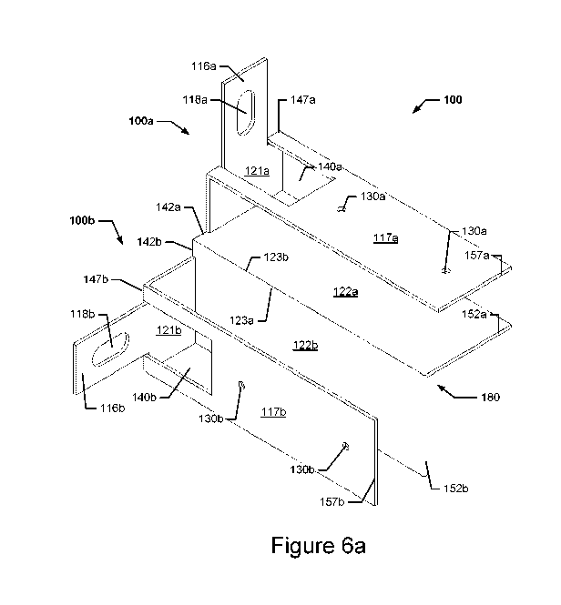
Figures 6a, 6b and 6c show one of the corner brackets 100 for assem-
bly of two respective boards la, lb; lb, 1c; lc, ld; ld, la of the window
mounting collar 1 of Figure 5 into a collar corner and for affixing the window
mounting collar 1 to the exterior face of the building façade 8 so as to sur-
round the window opening. The corner bracket 100 is symmetrical so as to be
divided into a first bracket part 100a and a second bracket part 100b, which
is formed similar to the first bracket part 100a, but symmetrically over a
symmetry plane. The bracket part 100a comprises one holding plate 121a,
one associated base arm 116a, one associated abutment plate 117a and one
associated flange 122a. The bracket part 100b similarly comprises one hold-
ing plate 121b one associated base arm 116b, one associated abutment plate
117b and one associated flange 122b.
Generally, in the context of the present specification it is noted that
the term "associated" when used in relation to the abutment plate, flange,
holding plate and base arm of the corner bracket should be understood as
"forming part of the same of the two bracket parts". The "associated board"
is equivalently the board positioned between a abutment plate and associated
flange of a corner bracket.
Each holding plate 121a, 121b and its associated base arm 116a,
116b, respectively, extend in planes parallel with and having back surfaces
abutting the exterior face of the building facade 8.
The base arms 116a, 116b are formed as respective extensions of
their associated holding plate 121a; 121b, extending away from a plane of
the associated said holding plate 121a; 121b. Each holding plate 121a, 121b
is at one edge attached to the associated base arm 116a, 116b. The base
arms 116a, 116b have a width (defined as the direction extending along a
CA 02916756 2015-12-23
WO 2015/000490
PCT/DK2014/050202
17
longitudinal direction of the associated board) somewhat smaller than the
width of the holding plates 121a, 121b, and extend away from the holding
plate 121a, 121b. The base arms 116a, 116b further each comprise one
elongated, approximately elliptical receiving aperture 118a, 118b positioned
approximately at the centre of the respective base arm 116a, 116b in the
width direction, and extending in the same direction as the respective base
arm 116a, 116b. The receiving apertures 118a, 118b receives a fixation
member in the form of a screw or bolt therethrough and into the building fa-
çade 8, such as to fixate the collar 1 to the façade 8 when the board is posi-
tioned to be held between the associated flange 122a; 122b and abutment
plate 117a; 117b.
Each abutment plate 117a, 117b extends approximately perpendicu-
larly away from its associated holding plate 121a, 121b and base arm 116a,
116b. Each abutment plate 117a, 117b comprise a proximal end 147a, 147b
configured to be proximal and a distal end 157a, 157b configured to be distal
to the exterior face of the façade 8 in the affixed position of the collar 1.
Each
abutment plate 117a, 117b is connected at its proximal end 147a, 147b, re-
spectively, to the associated holding plate 121a, 121b and associated base
arm 116a, 116b at a line dividing the associated holding plate 121a, 121b
and the associated base arm 116a, 116b. Each abutment plate 117a, 117b is
adapted to abut a respective outer surface of the associated board la, lb, lc,
ld in the affixed position of the collar 1.
In the embodiment of Fig. 6a to 6c each abutment plate 117a, 117b
does not extend beyond a plane in which its non-associated flange 122b,
122a, respectively, extends. The abutment plate 117a with which the flange
122b is not associated is referred to as the non-associated abutment plate
thereof. Similarly, the abutment plate 117b with which the flange 122a is not
associated is denoted the non-associated abutment plate thereof.
Each abutment plate 117a, 117b further comprises two retention aper-
tures 130a, 130b positioned for receiving an oblong retention member (not
shown) in the form of a screw or a bolt inserted through the associated
abutment plate 117a, 117b, through the board la, lb, lc, ld to be posi-
tioned between the associated abutment plate 117a, 117b and flange 122a,
122b, and through the associated flange 122a, 122b. Hereby, the board may
be pressed in between the associated abutment plate 117a, 117b and flange
CA 02916756 2015-12-23
WO 2015/000490
PCT/DK2014/050202
18
122a, 122b to retain the board, the abutment plate 117a, 117b and flange
122a, 122b being pulled against each other by means of the retention mem-
ber. The abutment plate 117a, 117b additionally comprises a cut-out 140a,
140b extending from its proximal end towards its distal end, which provides
for the base arm 116a, 116b to be folded into position, see further below re-
garding manufacture of the brackets according to the invention.
Each flange 122a, 122b extends approximately perpendicularly away
from its associated holding plate 121a, 121b, and is positioned at a mutual
distance from and in parallel with its associated abutment plate 117a, 117b.
Each flange 122a, 122b has a proximal end 142a, 142b configured to be
proximal, and a distal end 152a, 152b configured to be distal to the associ-
ated holding plate 121a, 121b. The flange 122a, 122b is attached at one
edge at its proximal end to an edge of its associated holding plate 121a,
121b. The flange 122a, 122b is wider than its associated holding plate 121a,
121b.
Finally, the bracket parts 100a, 100b are connected via flange arm 180
comprising the two flanges 122a and 122b. Each flange 122a, 122b has an
attaching edge 123a, 123b, respectively, extending from the proximal end
142a, 142b to the distal end 152a, 152b. The attaching edges 123a, 123b are
attached to each other along the entire part of the attaching edges 123a,
123b, but may in other embodiments extend only along part of the edges
123a, 123b. For example one or more discontinuations could be provided be-
tween the ends 142a, 152a; 152a, 152b, respectively, the ends being at-
tached to each other, which can save bracket material. The flanges 122a,
122b extend approximately perpendicularly to each other, forming an inner
flange corner supporting the inner faces of the associated two boards, for
example la, lb, in the affixed position of the boards.
The symmetry plane dividing the corner bracket 100 into the two
bracket parts 100a, 100b extends through the attaching edges 123a, 123b of
the flanges 122a and 122b.
In Figure 5 associated pairs of the boards la, lb, lc, ld are received
between a respective flange 122a, 122b and an associated abutment plate
117a, 117b of each corner bracket 100. Each board la, lb, lc, ld has an
outer board surface, which is parallel with and faces away from the exterior
face of the façade 8. Each flange 122a, 122b and associated abutment plate
CA 02916756 2015-12-23
WO 2015/000490
PCT/DK2014/050202
19
117a, 117b are thus in contact with an associated one of the boards la, lb,
lc, ld, the distal end 152a, 152b, 157a, 157b of each flange 122a, 122b
and/or of each abutment plate 117a, 117b being positioned at a distance
from the outer board surface of its associated board la, lb, lc, ld. The re-
spective distal ends 152a, 152b, 157a, 157b of the flanges 122a, 122b and
abutment plates 117a, 117b are positioned at a distance from the outer
board surface of the associated board la, lb, lc, ld of approximately 200
mm, i.e. about 50 % of a length measured in the depth direction of the collar
1 of the respective flange 122a, 122b or abutment plate 117a, 177b.
Note that according to the invention the bracket parts 100a and 100b
need not necessarily be similar, and the holding plates 121a, 121b, base
arms 116a, 116b, abutment plates 117a, 117b or flanges 122a, 122b may be
of respective different shapes or sizes. For example the length of abutment
plates 117a, 117b and flanges 122a, 122b, respectively, may be different
from each other.
Figure 7 shows a top view of a work-piece W punched out from one
single sheet of plate metal. The work-piece W is subsequently folded or bent
into the corner bracket 100 of Figure 6a. The folding lines are shown with
dashed lines. All foldings are by approximately 900. Similarly, the holding
bracket 200 of Figure 8 and joining bracket 300 of Figure 9 are manufactured
by punching out from a single sheet of plate metal.
Figure 8 shows the holding bracket 200 shaped like the corner bracket
100 of Figures 5a, 5b and Sc, but with the difference that it comprises only
one single associated abutment plate 217 and flange 222, one associated
holding plate 221 and one associated base arm 216. The holding bracket 200
may be manufactured by cutting along the attaching edges 123a, 123b of the
corner bracket 100 to separate the two flanges 122a, 122b. The holding
bracket is thus adapted to hold a board la, lb, lc, ld to the exterior face of
the façade 8 anywhere along the boards.
Figure 9 shows a joining bracket 300 shaped like the corner bracket
100, but with the difference that an angle between planes in which the
flanges 322a, 322b extend is approximately 1800. Hereby, the abutment
plates 317a, 317b and flanges 322a, 322b extend in a mutual plane, so that
the joining bracket 300 may be used to join two board pieces of one collar
board la, lb, lc, ld extending in a mutual longitudinal direction. Each board
CA 02916756 2015-12-23
WO 2015/000490
PCT/DK2014/050202
la, lb, lc, ld may thus be received between a respective flange 322a, 322b
and its associated abutment plate 317a, 317b of said joining bracket 300, see
further below. The joining bracket 300 can be manufactured by avoiding the
folding along the attaching edges 123a, 123b of the corner bracket 100 as
5 shown in Figure 6a. The joining bracket 300 can also be used as a holding
bracket, i.e. without joining two board pieces.
The window frame is mounted in the mounting collar and can be fixed
in place by conventional means. For example, screws could be inserted
through the window frame and into the mounting collar. If the material of
10 mounting collar allows the screws to be pulled out too easily, it may be
nec-
essary to arrange a plate at the outside face of the mounting collar. A screw
can then be inserted through the window frame, through the mounting collar
and through the plate to provide a firmer connection. However, if external
wall insulation is already in place, then positioning of a plate at the
outside
15 face of the mounting collar can be difficult.
Therefore, it has been found to be particularly advantageous to use a
frame mounting clip to mount the window frame in the mounting collar. The
frame mounting clip has a base plate and first and second side plates extend-
ing from opposite ends of the base plate, substantially perpendicular to the
20 base plate and substantially parallel to each other. The clip can be
arranged
on the mounting collar at its second end such that the first side plate abuts
an inside face of the mounting collar and the second side plate abuts an out-
side face of the mounting collar. In order to mount the window frame in
place, a screw is inserted through the window frame, the first side plate of
the mounting clip, through the window mounting collar and through the sec-
ond side plate of the mounting clip.
This clip allows for a stronger attachment of the window frame to the
mounting collar and allows for easy positioning of the clip because the base
plate of the mounting clip is always easily accessible, even when external
wall
insulation is in place surrounding the mounting collar.
The clip can be made of any suitable material with sufficient rigidity
and strength and that can accept screws. The clip could, for example, be
made of metal. However, materials with a lower thermal conductivity are pre-
ferred. In one embodiment, the first and second side plates of the clip each
comprise a pre-bored hole to accept a screw. Figure 10 shows an example of
CA 02916756 2015-12-23
WO 2015/000490
PCT/DK2014/050202
21
a mounting clip system. The mounting clip 23 has a base plate 24 and first
and second side plates 25, 26 extending from opposite ends of the base plate
24. The clip 23 is shown arranged on the mounting collar 1 at its second end
6 such that the first side plate 25 abuts an inside face 2a of the mounting
collar 1 and the second side plate 26 abuts an outside face 2b of the mount-
ing collar 1. The first side plate 25 of the window mounting clip 23 is shaped
as a wedge, having a thickness at its end furthest from the base plate 24 that
is greater than the thickness of the first side plate 25 of the window
mounting
clip 23 at its end that is adjoined to the base plate 24.
When assembling the collar 1 of Figure 5, first the boards la, lb, lc,
id are cut (e.g. sawed) out from longer board members. If this results in
surplus board pieces, examples of surplus board pieces shown as board
pieces le and if in Figure 5, of too short lengths, these may be further cut
to
appropriate sizes to be joined by means of one or more joining brackets 300
to form a resultant board, in the example of Figure 5 board lb, of suitable
length. The boards may alternatively be manufactured from the factory in
suitable lengths so as to avoid the sawing operation.
Two respective of the boards la, lb, lc, id of the collar 1 are subse-
quently positioned between abutment plate 117a, 177b and associated flange
122a, 122b, respectively, of a first corner bracket 100 to be preliminary re-
tained to the corner bracket 100 between the abutment plates 117a, 177b
and the associated flanges 122a, 122b. The associated board la, lb, lc, id
is then permanently retained by means of oblong retention members in the
form of bolts (not shown) inserted through the retention apertures 130a,
130b of the abutment plates 117a, 117b, through the associated board la,
lb, lc, id, and through further, associated retention apertures (not shown)
of flanges 122a, 122b. Hereby, the two associated boards la, lb, lc, id are
positioned in the bracket 100 as shown in Figure 5, the boards la, lb, lc, id
forming a collar corner of the collar 1. This procedure is subsequently per-
formed with each corner bracket of the collar 1, thereby resulting in a fin-
ished collar 1 as shown in Figure 5. The boards may alternatively be inserted
preliminarily in all the collar corners before permanent retention is achieved
by means of the bolts. One or more holding brackets 200 are before or after
attachment of the corner brackets 100 attached to the boards la, lb, lc, id
to further attach the boards la, lb, lc, id to the façade 8. Screws or bolts
CA 02916756 2015-12-23
WO 2015/000490 PCT/DK2014/050202
22
are inserted through receiving apertures 18, 118a, 118b, 218, 318a, 318b
into the façade 8 to affix the collar 1 to the façade 8; this may be done be-
fore, during or after assembly of the collar 1.
In the embodiment shown the mounting clip 23 forms one part of a
clip system. The clip system comprises the mounting clip 23 and a separate
plate 27. The face of the first side plate 25 of the mounting clip that faces
away from the second side plate has ridges 28. The peaks of the ridges are
substantially parallel to the base plate 24 of the clip. The clip system also
comprises a separate plate 27 having ridges 29 on one of its faces that are
adapted to cooperate with the ridges 28 on the first side plate 25 of the
mounting clip. A window frame not shown can be set in place by positioning
the window frame in the mounting collar 1 and then pushing the separate
plates 27 in between the window frame and the mounting clip 23. The frame
is then fixed in place with screws.