Note : Les descriptions sont présentées dans la langue officielle dans laquelle elles ont été soumises.
CA 02917058 2015-12-30
PCT/AU2014/000697
ALIGNMENT SYSTEM FOR ALIGNMENT OF A DRILL ROD DURING DRILLING
TECHNICAL FIELD
100011 The present invention relates to alignment devices and particularly
to those which
can be used to align drilling rigs to ensure correct drilling azimuth and/or
dip angle whilst the
drill rod is in the hole.
BACKGROUND ART
l00021 In mining, whether underground or surface mining (e.g. diamond
mining, goldmining
etc), once the mine has been formed, exploratory drill holes are typically
then formed to try to
locate ore bodies. These drill holes can have a length of up to 1 km bur are
usually much shorter.
[00031 Initially, geologists will determine the likely location of an ore
body or seam. The
mine geologist will design the mine and the location of the exploratory holes
and the surveyors
will place survey markers in appropriate locations marking the intended hole
positions. The
survey markers will comprise a first mark on one wall of the mine and a second
mark on an
opposed wall of the mine. The markers are usually small reflective squares
pinned to the mine
wall. A "string line" between the two markers will show exactly the direction
that the drilling
apparatus will need to drill. This is known technology. For surface mines, a
pair of pegs or
markers inserted into the ground are typically used.
[00041 The direction typically includes the two components "elevation" and
the "azimuth".
The elevation is the angle to the horizontal at which the drill rod is
oriented and the azimuth is
the degree or direction about a vertical axis that the drill rod is oriented.
[0005] Ensuring the correct "elevation" is usually not a great problem as
the drill rig can
quite easily be angled upwardly or downwardly to the correct elevation.
However, ensuring the
correct "azimuth" has been a problem to date and even a small error in the
azimuth can cause
rejection of the bore hole.
[0006] Once the survey markers have been completed, a drill rig is
positioned to drill the
required core samples. The drill rig is usually a very large self-propelled
apparatus. A typical
apparatus comprises a wheeled or tractor vehicle which has a forwardly
extending boom arm and
attached to the boom arm is a drill rig. The drill rig is attached to the boom
arm such that it can
adopt any required angle (in Figure 1 the drill rig is pointing downwardly)
CA 02917058 2015-12-30
2
WO 2015/000023 PCT/AU2014/000697
[0007] This type of apparatus is well-known and there are many differe
such apparatus, such as that illustrated in Figure 3 for example which is an
example of a skid-
steered self-propelled rig.
[0008] Once the drill rig is roughly in position (determined by the survey
markers), it needs
to be very accurately adjusted to the survey markers. Once the adjustment is
complete, the drill
rig is secured in position and this is usually done by bolting the drill rig
to the mine floor using a
known type of feed frame positioner. For larger rigs, the weight of the rig
can be sufficient to
maintain the position.
[0009] The drill rig is then turned on to drill the required hole.
[0010] The present invention is directed to a laser unit device that can be
used to very
accurately correctly adjust the azimuth of the rig prior to bolting (securing)
the rig into position.
Preferably, the laser unit device is a gyroscopically aligned laser unit
device.
[0011] Conventionally, string lines are used to align the rig prior to
securement of the rig
into position. That is, a string line is stretched between the survey markers
on the opposed walls
of the mine shaft. The apparatus is then positioned as close as possible to
the string line and is
aligned with the string line (that is the drill rig is aligned to be parallel
with the string line to get
the correct azimuth). Because of the size and shape of the apparatus, it is
not possible to place
the apparatus against the string line and usually the apparatus will be some
distance away from
the string line. For a "normal" sized apparatus, the apparatus will still be
about 1 m away from
the string line but for a larger apparatus, this can be between 3 to 4 m from
the string line. A
measuring tape is then used to accurately measure the distance between the
front and the rear of
the apparatus and the string line to ensure that the apparatus is exactly
parallel with the string line
such that when a hole is drilled, the hole will be at the correct azimuth.
[0012] In practice, it is difficult to obtain the level of accuracy that is
demanded by the
geologists using this known technique of string lines and measuring tapes.
Once a pilot hole is
collared, and it reaches its first survey mark (normally at approximately 5 to
15 meters) a survey
tool is then inserted into the drilled hole. This survey tool normally
provides a reading of both
the elevation and the azimuth of the pilot hole. The driller then checks this
against the hole plans
and if not exactly correct, the hole will need to be redone.
[0013] The cost of drilling each hole can be many thousands of dollars and
it is not unknown
for the cost to be about $100,000 per hole. A drilling contractor is not paid
for a -rejected" hole.
CA 02917058 2015-12-30
3
WO 2015/000023 PCT/AU2014/000697
[0014] There is also a significant secondary issue once the rig has been
prior to drilling and that is maintaining the drill rod in the correct
orientation and direction whilst
drilling is taking place.
[0015] In the present specification, the term "drill rig" is not intended
to be limiting and
includes any type of drill or surface rig adapted to drill a hole in any type
of mine including a
surface or underground mine.
[0016] It will be clearly understood that, if a prior art publication is
referred to herein, this
reference does not constitute an admission that the publication forms part of
the common general
knowledge in the art in Australia or in any other country.
SUMMARY OF INVENTION
[0017] The present invention is directed to a laser alignment device, which
may at least
partially overcome at least one of the abovementioned disadvantages or provide
the consumer
with a useful or commercial choice.
[0018] With the foregoing in view, the present invention in one broad form,
resides in an
alignment system for alignment of a drill rod during drilling of the hole
including a laser device
mounted relative to a drill rig to issue at least one laser emission and at
least one detector device
to detect at least one laser emission whereby the laser emission is used to
determine the position
of the drill rod in relation to the centre of the partially drilled hole
whilst the drill rod is in the
partially drilled hole.
[0019] According to a preferred embodiment, the system for alignment of the
drill rod will
typically include more than one component. Preferably, there will be at least
a down hole
component and a surface component provided in relation to the drill rig at the
head of the hole
being drilled.
[0020] Normally, the at least one laser device is provided in or as a part
of the down hole
component. The at least one detector device may also be provided in or as a
part of the down
hole component. The surface component is typically a reporting component in
order to advise an
operator of the alignment or misalignment of the drill rod.
[0021] The alignment system of the present invention includes at least one
laser device
mounted relative to a drill rig to issue at least one laser emission. More
than one laser device can
be provided depending upon the configuration and operation of the particular
alignment system.
CA 02917058 2015-12-30
4
WO 2015/000023 PCT/AU2014/000697
Further, any one or more of the laser devices provided can be directed in an:
the particular configuration of the alignment system has a large bearing on
the number and
orientation of the laser devices provided.
[0022] The at least one laser device of the present invention may emit a
steady beam or a
pulse or a combination. Depending upon the use to which the laser device is
put, the type of
emission from the at least one laser device can be configured appropriately.
The emission from
the at least one laser device can be focused or dispersed to any degree.
[0023] The at least one laser device is typically mounted relative to a
drill rig and more
preferably, relative to the drill rod being used to drill the hole. According
to the most preferred
form, the drill rod provided is typically hollow or at least partially hollow
and of the at least one
laser device is provided as a part of the down hole component of the system of
the present
invention, within a hollow portion of the drill rod.
[0024] The at least one laser device and/or the down hole component of the
system may be
provided within a guide tube or similar arrangement which is received,
preferably removably,
within the hollow portion of the drill rod.
[0025] Alternatively, the at least one laser device may be provided within
or relative to a
housing portion which is attachable in-line over the length of the drill rod.
Typically, the elongate
drill rod used is formed from a series of portions attached to or relative to
one another in order to
form the drill rod. The housing portion preferably mimics the external
dimension of an elongate
drill rod and has attachment portions at either end allowing the attachment of
the housing portion
to a leading drill rod portion and if necessary following drill rod portion in
order to provide a
housing portion which is basically a part of the drill rod.
[0026] The at least one laser device may be removable from within the drill
rod, guide tube
or housing portion. Alternatively, the at least one laser device may remain in
place, particularly
while the drill rod is in use.
[0027] Typically, the at least one laser device is provided in or relative
to a portion of the
drill rod behind the drill head and preferably, is located closer to the drill
head.
[0028] The least one laser device can be used in a number of different ways
in order to assist
with alignment of the drill rod during use. For example, the at least one
laser device can be used
to indicate an orientation or position of the drill rod and/or to convey
information from one or
more sensors or measurement devices to be surface component of the system of
the present
CA 02917058 2015-12-30
WO 2015/000023 PCT/AU2014/000697
invention.
[0029] In one embodiment, the at least one laser device can be directed
forwardly, namely in
the direction of the drill rod cutting head. In this configuration, the drill
rod is normally used to
indicate the orientation position of the drill rod or to provide a measure of
difference from the
intended path or centre of the proposed drill hole.
[0030] At least one laser device may be provided directed rearwardly toward
the drill rig.
[0031] Still further, at least one laser device may be provided directed
laterally or radially,
whether radially inwardly or radially outwardly.
[0032] Combinations of laser devices can be provided which are directed in
more than one
direction, for example, both forwardly and then radially or rearwardly and
radially, or forwardly
and rearwardly or both laterally or radially inwardly and outwardly. A single
laser device may be
provided which is directed in any one or more directions.
[0033] The at least one laser device can be used to give an indication of
or to measure the
distance to another object or component. For example, a laser device can be
used to measure the
distance between that the pipe and a wall of the hole being drilled or
internally, to the centre of
the rod or another portion of the rod. Normally, an appropriate calibration
will be made such that
the measurement made during the drilling of the hole can be used to then give
an indication of
the alignment of the drill rod when drilling, and/or an indication or
measurement of any
difference between the alignment in use and the desired alignment of the drill
rod.
[0034] In a particularly preferred embodiment, particularly if it least one
laser device is
directed radially outwardly relative to the drill rod, it is preferred that
the housing portion
provided has one or more openings therein in order to allow the at least one
emission to exit the
drill rod and preferably, for a return emission to enter the housing portion
to be detected by at
least one detector.
[0035] The alignment system of the present invention also includes at least
one detector in
order to detect at least one emission issued by at least one laser device. The
at least one detector
can be any type of detector and for example, may be a static detector such as
a plate or other
device which may simply register the position at which the emission strikes
the detector or
alternatively, the detector may be a detector which is capable of receiving an
emission or return
emission and determining one or more aspects or parameters of the emission or
in relation to the
emission such as elapsed time from the issue of a primary emission to the
receipt of a return
CA 02917058 2015-12-30
6
WO 2015/000023 PCT/AU2014/000697
emission.
[0036] The at least one detector may be fixed relative to the drill rig or
preferably to the drill
rod or alternatively, the at least one detector may be movable. According to a
particularly
preferred embodiment, the at least one detector may be movable within the
drill rod along a
longitudinal length of the drill rod. The movement of the at least one
detector within the drill rod
may be movement forced or driven by a sample which is typically dirt or rock
which is received
within the drill rod as a result of the drilling.
[0037] The preferred surface component of the alignment system of the
present invention
will typically be provided in association with the drill rig at the head of
the hole being drilled.
Typically, the at least one detector or other sensor device provided in or as
a part of the down
hole component, will collect information and then send this information to the
surface
component in order to allow the information or information calculated from
that collected by the
detector or sensor, to be viewed or displayed to the operator. Preferably, the
surface component
of the system may be provided with one or more communications pathways to
allow information
to be transmitted from the surface component to a remote display or other
device. Typically, the
operator in charge of the drill rig will not be located on the drill rig and
will typically remain
away from the drill rig for safety purposes. Information will typically be
transmitted to a device
which can be carried by the operator and according to which, the operator can
monitor the
information gathered by the alignment system of the present invention.
[0038] According to one preferred embodiment, the alignment system of the
present
invention will also provide information which allows the drill hole to be
profiled as the down
hole component moves downwardly within the hole or alternatively, as the down
hole component
is drawn out of the hole or both. In this way, the alignment system of the
present invention and
particularly, the at least one laser device provided as a part of the
alignment system can be used
for a dual purpose of aligning the drill rod or measuring any misalignment of
the drill rod and
also be used to create a profile model of the drill hole which may aid
operators. Typically, a
three-dimensional profile model can be created using the elements of the
alignment system
provided according to the present invention and typically using the
information provided together
with appropriate 3-D modelling software.
[0039] Additionally, at least one laser device provided as a part of the
alignment system of
the present invention may be used to properly aligned or aid in the alignment
of the drill rod
portions during attachment and detachment of the drill Rod portions relative
to one another
CA 02917058 2015-12-30
7
WO 2015/000023 PCT/AU2014/000697
during drilling.
[0040] Therefore, as an alternative aspect, the present invention may
reside in a drill rod
alignment detector system including a laser device mounted relative to a drill
rig for indicating a
drill rod orientation and an alignment detector device adapted to be placed at
least partially in a
partially drilled hole and having a laser point detection portion that detects
where a laser light
point of the laser device strikes the face of the detector enabling
calculation of the position of the
drill rod in relation to the centre of the partially drilled hole.
[0041] Normally, the alignment tool discussed above is used during the
original rig setup
and the alignment tool is then removed from the drill rig. According to this
aspect of the present
invention, normally, after the hole is drilled to a sufficient indicated
depth, the alignment tool can
be reattached to the drill rig. Normally, no changes are made to the rig setup
during this process,
that is the alignment is not adjusted. The alignment detector attachment is
then typically placed
into the hole which has been partially drilled and the alignment tool or laser
is directed at the
alignment detector attachment.
[0042] The alignment detector attachment will preferably provide data to a
display device
outside the hole of the orientation of the laser and thereby of the drill rod
in order to allow
adjustment of the alignment tool and thereby adjustment of the drill rod to
ensure correct drilling.
[0043] This alignment detector attachment preferably includes a laser point
detection plate
(typically an optical detection array) that detects where the laser light
point strikes the face of the
detector and will calculate this position in relation to the centre of the
drilled hole, normally in
two axes.
[0044] The orientation of the laser point detection plate in relation to
the orientation of the
alignment tool is preferably measured by rotational alignment detectors, which
may be
inclinometers measuring one or two axes or other similar inclination measuring
device.
[0045] The alignment detector attachment is typically centred in the
drilled hole by a
mechanical centring mechanism. This will usually be a length of machined rod ¨
similar to a
drill rod and either of the same diameter as the drill rod used to drill the
hole, or extended to this
diameter using collars, extensions, bushes or similar devices.
[0046] This information or sufficient data to allow a visual representation
of the orientation
of the laser is preferably transmitted to a display device outside the hole.
Transmission of this
infotination may be by wireless communication means or by way of a hard wired
connection.
CA 02917058 2015-12-30
8
WO 2015/000023 PCT/AU2014/000697
The information is then processed in software running on the display device
any rotation of the alignment tool within the hole. An image is preferably
generated and
displayed on the display in an easy to read information display depicting the
angular offset of the
hole from the centre line of the drill in two axes.
[0047] The alignment detector attachment will preferably be self centering
in the hole and
also be capable of self centering in a hole of any larger size. The alignment
detector attachment
will preferably have a detector allowing for positional and/or rotational
alignment relative to the
alignment tool or to determine alignment relative to the alignment tool.
[0048] Any of the features described herein can be combined in any
combination with any
one or more of the other features described herein within the scope of the
invention.
[0049] The reference to any prior art in this specification is not, and
should not be taken as
an acknowledgement or any form of suggestion that the prior art forms part of
the common
general knowledge.
BRIEF DESCRIPTION OF DRAWINGS
[0050] Various embodiments of the invention will be described with
reference to the
following drawings, in which:
[0051] Figure 1 is a perspective photograph of a conventional boom operated
drill rig in
operation.
[0052] Figure 2 is a side elevation view of a conventional skid-based drill
rig in the installed
configuration and anchored to the floor.
[0053] Figure 3 is a schematic side elevation view of a drill rod with a
downhole drill
alignment component according to a preferred embodiment of the present
invention provided in a
guide tube.
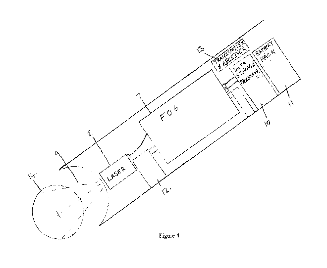
[0054] Figure 4 is a detailed sectional view of the down hole drilled
alignment component of
the configurations illustrated in Figure 3.
[0055] Figure 5 is a schematic side elevation view of a downhole drill
alignment component
according to an alternative embodiment of the present invention.
[0056] Figure 6 is a schematic side elevation view of a downhole drill
alignment component
CA 02917058 2015-12-30
9
WO 2015/000023 PCT/AU2014/000697
according to another alternative embodiment of the present invention.
[0057] Figure 6A is a sectional view of a forward portion of the component
illustrated in
Figure 6.
[0058] Figure 7 is a sectional side view of yet another alternative
embodiment of the
downhole component according to a preferred embodiment of the present
invention.
[0059] Figure 8 is a sectional side view of still another alternative
embodiment of the
downhole component according to a preferred embodiment of the present
invention.
[0060] Figure 9 is a sectional view of yet another alternative embodiment
of the downhole
component according to a preferred embodiment of the present invention.
[0061] Figure 10 is a schematic side elevation view of an alternative
embodiment of the
system of the present invention.
[0062] Figure 11 is a schematic side elevation view of an alternative
embodiment of the
system of the present invention.
[0063] Figure 12 is a schematic side elevation view of an alternative
embodiment of the
system of the present invention using a laser device to orient drill rod
portions before attachment.
[0064] Figure 13 is a schematic illustration of an alignment/orientation
detector according
to a preferred embodiment of the present invention.
[0065] Figure 13 is a detailed view of the detector plate illustrated in
Figure 13 showing the
laser point.
[0066] Figure 13B is a detailed view of the detector plate illustrated in
Figure 13 showing
the output display according to a preferred embodiment of the present
invention.
DESCRIPTION OF EMBODIMENTS
[0067] According to a preferred embodiment, a laser device for use with a
drilling rig and a
drill rig with the device attached, are provided.
[0068] A conventional drill rig is illustrated in Figure 2. The drilling
rig itself is of a
commercial type and basically comprises a pair of parallel steel feed rails
which will typically
have a length of between 1.5 m up to 6 m. A carriage 1 slides over the top of
each feed rail, and
CA 02917058 2015-12-30
WO 2015/000023 PCT/AU2014/000697
can reciprocate between the retracted position illustrated above and an exter
the carriage has been moved to the front of the feed rails 10. A hydraulic ram
powers the
carriage between its positions. On top of the carriage is a high speed
hydraulic rotating
apparatus. The rotating apparatus will typically rotate at speeds of between
1000-10,000 rpm. A
drill rod (not illustrated) passes into the front opening of the rotating
apparatus and is rotated by
the rotating apparatus. In a front part of the drill rig is a "centraliser"
through which the rods pass
and the function of the centraliser is to keep the rods aligned and to
minimise "wobble". A
hydraulic piston is associated with the centraliser. The piston extends to
lock the drill rod when
the drill rod has stopped rotating.
[0069] Figures 3 to 13 show different preferred embodiments of alignment
systems for
alignment of a drill rod during drilling of the hole. All of the embodiments
illustrated including
at least one laser device mounted relative to a drill rig to issue at least
one laser emission and at
least one detector device to detect at least one laser emission whereby the at
least one laser
emission is used to determine the position of the drill rod in relation to the
centre of the partially
drilled hole whilst the drill rod is in the partially drilled hole.
[0070] Figure 3 shows the simplest configurations of the present invention.
As illustrated in
Figure 3, a drill rod 5 is provided to drill a hole 1. As the drill rod 5
extends downwardly, it
removes material to form a substantially cylindrical wall 2. As illustrated in
Figure 3, the drill
rod 5 is provided with an inner guide tube 3. A forward end of the inner guide
tube 6 is provided
adjacent to the drill head at the left-hand end of the figure. A downhole
component of the
alignment system of the present invention and is provided as a combined
inertial device 4 and a
housing 6 which includes at least one laser device adapted to issue an
emission laterally through
the openings 6A in the housing 6. In this aspect, the downhole component of
the alignment
system of the present invention can be moved relative to the cutting head of
the drill rod 5 as the
hole is drilled through the inner guide tube 3. As this occurs, the laser
emission and associated
detector within the downhole component can be used to profile the inside of
the drill hole by
measuring the separation distance between that the different sides of the
housing 6 and the wall 2
of the drill hole. The inertial device 4 can provide additional information
such as pitch, roll and
heading.
[0071] Figure 4 is a more detailed schematic view of the inner workings of
a downhole
alignment component. In this particular embodiment, the downhole component
includes a fibre
optic gyro (Inertial device) which is mounted using an appropriate bracket
mount 12. The inertial
device can be mounted in any way including a gimbal setup or bracket 12, and
the actual
CA 02917058 2015-12-30
11
WO 2015/000023 PCT/AU2014/000697
mounting method used is typically dependent upon the type of inertial devic
component illustrated in Figure 4 also includes a forwardly oriented laser
device 8. According to
this particular embodiment, the laser emits a dispersed beam 9 forwardly. A
position sensitive
device (P SD) 14 is provided in front of the dispersed beam 9 in order to
calculate the
position/orientation of the laser device.
[0072] The down hole alignment component also includes a data processor
with storage 10
and a battery pack 11 to provide power to the inertial device and the laser.
Also provided in the
downhole component is a transmitter and receiver in order to send and receive
information and
instructions from the downhole component to a surface component to process the
information.
Once the surface component of the system has received the information,
information can then be
either further processed by the surface component or transmitted, typically
via a wireless
transmission method such as Bluetooth or by hardwire to a computer processor,
typically a tablet.
One particularly preferred form of transmitter and receiver for use with the
downhole component
is one adapted for laser pulse communication such that laser pulses can be
transmitted
downwardly to the downhole component through the drill pipe (within which the
downhole
component is typically housed). The system of the present invention may
include repeaters or
signal boosters to aid with the transmission of the signal between the
downhole component in the
surface component.
[0073] There is provision in some drill rods to include a component known
as a core lifter
used to retrieve a sample from a formation. The retrieved sample may then be
evaluated to
determine its contents.
[0074] The drill string typically includes an open-faced drill bit, an
outer tube of a core
barrel assembly, and a series of connected drill rods, which may be assembled
section-by-section
as the drill bit and the core barrel assembly move deeper into the formation.
The outer tube of the
core barrel assembly may be connected to the drill bit and the series of drill
rods. The core barrel
assembly may also include an inner tube assembly, which may be releasably
locked to the outer
tube. With the inner tube assembly locked to the outer tube, the drill bit,
the core barrel assembly
and the drill rods may be rotated and/or pushed into the formation to allow a
core sample to be
collected within the inner tube assembly. After the core sample is collected,
the inner tube
assembly may be unlocked from the outer tube. The inner tube assembly may then
be retrieved
using a retrieval system, while portions of the drill string remain within the
borehole.
[0075] The core sample may be removed from the retrieved inner tube
assembly, and after
CA 02917058 2015-12-30
12
WO 2015/000023 PCT/AU2014/000697
the core sample is removed, the inner tube assembly may be sent back and 11
tube. With the inner tube assembly once again locked to the outer tube, the
drill bit, the core
barrel assembly and the drill rods may again be rotated and/or pushed further
into the formation
to allow another core sample to be collected within the inner tube assembly.
Desirably, the inner
tube assembly may be repeatedly retrieved and sent back in this manner to
obtain several core
samples, while portions of the drill string remain within the borehole. This
may advantageously
reduce the time necessary to obtain core samples because the drill string need
not be tripped out
of the borehole for each core sample.
[0076] The particular embodiment illustrated in Figure 5 includes a PSD
17or similar
device placed inside the core lifter 15. When the core lifter is seated the
housing 16 including
the PSD 17 or similar device is inside core lifter case. A laser 18 is
provided in a downhole
component of the system of the present invention and the laser preferably
emits a dispersed beam
19 inside the core lifter tube onto the PSD 17. The PSD 17 is normally
separated from the laser
over a distance of approximately 3 meters 21. The information gained from the
relative positions
of the PSD 17 and the dispersed beam 19 can be used to calculate the
orientation of the drill rod.
As drilling was undertaken, the core is forced upwardly within the core lifter
tube, and the laser
device can be used to profile the inside of the drill hole. Preferably, the
PSD 17 moves up the
core lifter tube and further information can be gained as to the orientation
of the drill rod and the
drill hole with the aid of an inertial device 20 for heading reference, pitch
and roll information.
[0077] Figure 5 also shows the PSD 17 moving up the tube finally ending up
near the laser
18 which in turn creates a profile of the 3 metre run giving any deviation.
This can also be done
over the hole length of the pipe not just limited to the tube. The information
gained can be
downloaded into a separate or remote tool or tablet when the tube is brought
to the surface or this
can be done over the entire length of drill hole or pipe if there is no tube
as alternative.
Alternatively, this can be done each run, either way (as the tube goes down
into the hole and/or
as it is retrieved from the hole) and can be used to build a profile of the
drill hole in relation to
the initial setup orientation. The information can be constantly updated if
there is no tube. As
there are many types of drilling, some require tubes and some don't. Some have
the core sample
[dirt/rock and the like] come up inside of rods and some between hole wall and
the drill rod.
[0078] Figures 6 and 6A show another aspect to the invention. In this
particular
embodiment, the downhole component includes a forwardly oriented laser device
22 which emits
beam 23 into a beam splitter located at position 24. The beam splitter will
typically include a
reflective screen which splits the laser beam into multiple tubes. This is
illustrated particularly in
CA 02917058 2015-12-30
13
WO 2015/000023 PCT/AU2014/000697
Figure 6A. The laser beams produce a return emission back from the exteric
typically from the hole wall and the return emission is recorded via a
miniature CCTV and a
distance measuring device 25. Again, when this information is considered with
the information
which can be gained from the inertial device 27, this allows the downhole
component and the
system of the present invention to profile the inside of the drill pipe or
drill hole. The data can
be sent up the drill pipe or held on board inappropriate data storage to allow
the data to be
downloaded when tube is out of the hole.
[0079] Figure 6A shows a rear view of one possible configuration of beam
splitter. As the
beam reflects into the tubes, a component of the beam is allowed to continue
forward in the
direction of the drill head to collect information from that direction.
[0080] Figure 7 shows another possible embodiment of the down hole
component located
inside a drill rod. This embodiment is likely to particularly fine application
in the drill rod
configurations in which the sample travels between the drill rod and the drill
hole wall 33. As
can be seen from Figure 7, a series of laser beams 29 project outwardly from
the downhole
component which houses a laser device, onto the wall of the drill hole 33. The
downhole
component is located within the drill rod 30. The A forwardly directed laser
31 is provided
pointing in the direction of drilling to collect information from that
direction . According to the
embodiment illustrated, the downhole component can be either gimbal mounted or
bracketed
permanently or semi permanently inside the drill rod using a series of arms
32radiating from the
downhole component which can also be used to direct the laser beams 29. The
use of spaced
apart arms allows air and water to still pass through to the drill bit 34.
[0081] Figure 8 shows another aspect of the down hole components of the
present invention.
According to this embodiment, the downhole component is provided within a
housing 35 which
includes an inertial device. The at least one laser device of this
configuration is provided within
a central guide tube, but towards a forward end of the guide tube located
within the elongate drill
rod. An attaching assembly or mounting assembly 36 is provided at a forward
end of the guide
tube which mounts the laser 3'7 to direct the laser beam 39 from a forward end
of the guide tube
back towards the head of the hole. A PSD or similar device 39 is provided on a
forward end of
the housing 35. Again, the laser 37 is separated from the PSD 39 by distance
of approximately 3
meters. This distance may change as the core sample pushes the laser to award
of the housing 35
but over the distance, the information gained will show the deviation in the
hole.
[0082] Figure 9 shows yet another aspect of the invention. In this
particular embodiment, the
CA 02917058 2015-12-30
14
WO 2015/000023 PCT/AU2014/000697
laser devices 42 are still directed radially outwardly toward the wall 43 of
th
particular embodiment, a number of laser devices 42 are provided spaced around
the inside of the
housing 44 located within the drill Rod. Control electronics 40 controls the
operation of the laser
devices and the inertial device is 41 which in this embodiment is a number of
gyros. As
illustrated in this embodiment, each of the laser devices 42 emits a beam
which shines in two
directions, namely, to the inside of the rod to create a centre point 45 and
to the wall 43 of the
hole. This can also be used for finding the centre of the sample and profiling
the as it moves past
the laser beams, as well as for ensuring that the drill rod is centred within
the hole or foot
measuring any deviation from the centre by providing at least one detector to
measure the length
of any one or more of the respective laser beams.
[0083] Figure 10 illustrates a more complete view of the system according
to a preferred
aspect of invention. A laser inertial device 46 with transmitter and receiver
is located at the
surface, typically at attached to the drill rig. A clamp type device 47 is
provided to either
permanently clamp around the drill rod or to be removably located thereabouts
to send and to
receive information through a transmitter receiver collar 49 to aid with the
transmission of a
signal 50 to and from the downhole laser inertial device 51, which will
typically be of a form
similar to that illustrated in any one of figures 3 to 9. The signal 50
typically travels through the
drill rod, being sent and preferably received by the collar 47. The data
returned is in turn
processed by the surface component 46. Any data collected for calculations
made by surface
component 46 are preferably then communicated, typically via a wireless link
such as Bluetooth
to a remote tablet or PC which will display pitch, roll and/or heading to an
operator. With the aid
of the laser and the downhole inertial device 51, the system creates a three-
dimensional profile
model of the drill hole aiding operators and geologist by providing a full
profile from when the
hole was first started to the end of hole depth so that the rod orientation
and a deviation can be
calculated both at setup and then monitored over the course of the drilling
whilst the rod remains
in situ.
[0084] Figure 11 shows a different aspect of the invention where the
inertial system and data
processor 53 is mounted to the side of the drill rig or anywhere on the drill
rig. The laser device
52 is automatically positioned over the drill pipe or hole which is used to
send laser pulse signals
56through the booster collar 54 to the downhole laser inertial device 55 which
includes a
transmitter receiver 55. In this embodiment, the downhole device 55 can be
provided as a backup
up to laser device52 and inertial device 53 aw the two devices can be used in
concert to build up
a more accurate picture of the orientation of the drill rod and/or to profile
the hole.
CA 02917058 2015-12-30
WO 2015/000023 PCT/AU2014/000697
[0085] This configuration can be reversed so that the beam travels badl
hole and the data gained then processed and transmit calculated data to remote
PC or tablet.
[0086] Figure 12 shows another part of this invention, namely the use of
the lasers and
inertial devices to help accurately align the drill rod portions 57 when they
are being
automatically loaded by a rod handler device 58 onto the drill rig. This will
assist the correct
orientation of the drill rod so the threads can be accurately aligned
preventing rods being cross
threaded, under threaded and/or over tightened. It can also assist with the
makeup and breaking
of the threads in conjunction with the rod handler device 58. The Figure shows
the drill rod
portion 57 being aligned while it is on the automatic rod handler 58. The
laser and inertial device
59 emits a beam through the centre of the rod portion 57 which can be detected
by a detector
slaved to the automatic rod handler 58. A beam can be provided in an
alternative position such as
along a portion of the drill rod or parallel thereto. An additional laser
device may be provided at
position 60 in order to aid with the thread alignment, make up and break up of
threads by
providing accurate and detailed information about the position of the
respective rod ends as well
is the separation distance and the distance from the beam directed through the
centre of the Rod
portion 57. A control electronic inertial device 61 is preferably provided in
relation to the
additional laser device at position 60. This system is provided on the drill
rig 62 and all of this
process can work in concert with the drill rig electronics and hydraulics so
it can become a fully
automatic system.
[0087] Another alternative mechanism to allow the operator to ensure that
the hole drilled
remains on line, an alignment detector attachment and system can be provided
such as is
illustrated in Figure 13. The alignment tool head unit 101 with laser device
discussed above can
be used with a laser alignment detector attachment as a part of a system to
ensure that the hole 87
in the surface 88 remains online as it is drilled as well as at setup.
[0088] Normally, the alignment tool head unit 101 discussed above is used
during the
original rig setup and the alignment tool head unit 101 is then removed from
the drill rig.
According to the preferred embodiment illustrated in Figure 13, normally,
after the hole 87 is
drilled to a sufficient depth (generally at least 300mm and normally at any
depth or depths
following that), the alignment tool head unit 101 can be reattached to the
drill rig. Normally, no
changes are made to the rig setup during this process, that is the alignment
is not adjusted. The
alignment detector attachment 86 is then typically placed into the hole 87
which has been
partially drilled and the laser is directed at the alignment detector
attachment 86.