Note : Les descriptions sont présentées dans la langue officielle dans laquelle elles ont été soumises.
CA 02917091 2016-03-03
54106-1956
1
Device and method for operating functional units arranged in a
decentralized manner
FIELD OF THE INVENTION
The present invention relates to a device and a method for
operating decentralized functional units arranged in an
industrial installation.
BACKGROUND OF THE INVENTION
Such decentralized functional units are used in particular in
rail traffic networks, such as in the railroad for example,
where said units are used to control vehicle-influencing and/or
vehicle monitoring units and monitor them with regard to their
functionality and to accept process data and acknowledge it to
a central control and/or supervision center, such as a command
and control center or an interlocking for example. Signals,
switches, balises, line cables, track magnets and the like, as
well as sensors for capturing process variables of the moving
train, such as power consumption, speed and the like, can be
considered as train-influencing units, which thus give
instructions to the vehicle driver or even intervene directly
in the vehicle control or directly set a safe route. Likewise
balises and line cables, but also axle counters and track
circuits and other track availability notification systems can
be said to be train and track section monitors. Basically
however the present invention relates to all industrial
installations in which functional units are distributed over
longer distances and yet still have to be controlled centrally.
The central control in such cases can be handled by a control
center at a fixed location, but also by a virtual control
center not at a fixed location.
CA 02917091 2015-12-30
2013P12919W0
2
In rail traffic it is usually the case that these decentralized
functional units are controlled by an interlocking or a remote
interlocking computer. Standardized copper cables are generally
provided nowadays for data transfer between the interlocking and
the functional units in the track area, for which the classical
setting distance lengths, because of the physical transmission
parameters, the cable coatings (RLC), are restricted in practice
to an upper limit of 10 km. With certain types of functional
units however these upper limits can also lie at a maximum of
just 6.5 km.
Nowadays however data networks are already being employed in
railroads which are used for example for interchange of data
between adjacent interlockings or between the interlockings and
control systems. They are however not used in such a way as to
control and to monitor train-influencing and/or train-monitoring
functional units, in order by doing so to make it possible to
bridge almost any given setting distances. These networks are
instead designed as a type of data transport network (DTN), e.g.
an optical transport network, and are employed for the transfer
of data for the operational level and the like.
These types of data network allow a very much greater number of
degrees of freedom in respect of
O the definition of the position of the coupling points for
the connection of interlocking and control system
installations or parts thereof and thus of their
installation sites,
= the transmission method applied and the communication
distances between different installation parts.
CA 02917091 2015-12-30
2013P12919W0
3
These data networks thus occasionally make possible a significant
improvement in the price-performance ratio and yet still allow a
highly reliable and correspondingly safe interchange of data of
the railroad safety devices along rail installations.
Clear examples of applications for such data networks are branch
sections or sections with ETCS Level 2 or long tunnel sections,
for which currently, because of the limits for the setting
distance lengths with conventional interlocking cables, an
arrangement of interlocking computers within tunnels is made
necessary. The harsh deployment conditions obtaining therein
demand that the interlocking computers are encapsulated in
compartments or containers and/or operated with air conditioning.
Maintenance in these cases is correspondingly expensive. The
overall problem thus consists of interlocking and external
installation parts not being able to be at just any distance from
one another because of the limited setting distances.
The innovative data networks have a disadvantage however to the
extent that basically each centralized and decentralized
functional unit must be coupled in to such a data network in a
suitable manner via an access point and in a redundant manner for
reasons of availability. Thus at the moment a comparatively high
outlay for coupling with the data network is necessary at an
individual network node for connection of a functional units,
with at the same time only a comparatively small data transfer
rate in relation to the network capacity. While current glass
fiber networks for example allow for transmission rates extending
from GigaBit through to TeraBit transfer power, these
transmission rates are however only used very marginally in these
safety applications.
CA 02917091 2015-12-30
2013P12919W0
4
At the same time, above and beyond this, an economic interest on
the part of the railroad infrastructure operators can be
discerned for continuing to use the existing so-called long-life
interlocking cables (copper cables adapted to the rail tracks)
which are currently employed for the operation of the functional
units by the interlockings, for the control of the external
installations.
To achieve this object a device and a method are known from
European patent application EP 2 301 202 Al for controlling
and/or monitoring decentralized functional units arranged along a
traffic network, which includes the following core items:
a) A superordinate control system which interchanges information
with the decentralized functional units by means of data
telegrams,
b) A data transport network with a number of network access
points, wherein the superordinate control system is coupled
via at least one network access point to the data transport
network;
c) Communication units, which are connected in each case to a
network access point, wherein:
d) The decentralized functional units are grouped together into
subgroups, each with its own subnetwork and wherein
e) The subnetwork of each of the subgroups is coupled at each of
its two ends to the data transport network via a communication
unit and via a network access point.
In this way one digital transport network can be used for
coupling-in of the decentralized functional units, which is
robust in relation to a single error event in all respects yet
CA 02917091 2015-12-30
2013P12919W0
still allows a very clever use of copper cables widely used in
railroad technology, for example previously available
interlocking cables, and ultimately also only needs a
comparatively small number of network access points.
Such a device is able to be employed in this case in an
especially advantageous manner for a rail network for railroad
traffic. Consequently it is then expedient, in a further
advantageous embodiment, to couple traffic-monitoring and
traffic-control functional units, such as especially signals,
switches, axle counters, track circuits, point and linear-type
train influencing elements, into the data transport network by
means of the decentralized functional units.
The structure of technical installations, also especially in the
rail infrastructure, is designed on the basis of the more than
100 years of history of industrial systems engineering and
railroads, for robustness and reliability. As the system was
conceived in those days, the external elements of the railroad
safety installations in particular were connected by relatively
heavy cable wires, to enable the switching states over the
defined distances to be safely detected, i.e. the system was
designed in accordance with the peak loads with sufficient
reserve. With the switching process of the external elements
information is transferred via the energy injection points as
well. However it obviously also follows that the distances
possible are restricted by the detectable energy flow. As regards
current aspects of flexibility, costs and resource policy, these
established concepts, as well as the communication structure
disclosed by EP 2 301 202 Al, urgently require innovation in the
area of energy supply as well. As part of the modernization
CA 02917091 2015-12-30
2013P12919W0
6
initiated with such systems, the Mobility division of Siemens
will be undertaking fundamental innovations as regards its
interlocking architectures in the coming years, wherein the
solution for decentralizing the control and signaling systems
will be fully taken into account. This means that in the final
configuration all elements to be controlled and monitored
(signals, switches, train safety systems, track availability
systems such as axle counting points, railroad crossings) will be
given a control or signaling point locally on the track -
referred to below as an element controller EC or decentralized
functional unit DFE.
Since the strategic basis for the future derived from the two
architecture changes listed below in the electronic interlockings
from Siemens will lead to the previous coupling of information
and energy being removed, as well as the introduction of a real-
time-capable and high-availability wide area communications
system between the interlocking computer (central control unit)
and the setting and monitoring devices (Element Controllers EC)
required along the track, the supply of energy from the
interlocking to the element controllers on the track is to be
completely redesigned, for which a solution is disclosed in
international patent application WO 2013/013908 Al.
This solution provides for a device and a method for operating
decentralized functional units arranged in an industrial
installation, comprising:
a) A superordinate control system which interchanges
information with the decentralized functional units by means of
data telegrams,
CA 02917091 2015-12-30
2013P12919W0 =
7
b) A data transport network with a number of network access
points, wherein the superordinate control system is coupled via
at least one network access point to the data transport network;
c) Communication units, which are connected in each case to a
network access point and provide the decentralized functional
units with access to the data transport network,
d) An energy transport network to which the decentralized
functional units are connected and which supplies the
decentralized functional units with electrical energy; and
e) A number of intelligent energy stores connected to the
energy transport network, which accept energy and/or output it in
co-ordination with the superordinate control system and/or with
at least one of the other energy stores.
In this way the energy transport network is now completely
decoupled from an interlocking and, thanks to the energy stores
provided, can now be designed in respect of cabling and
transmission capacity for a certain predetermined basic load,
wherein load peaks of electrical power consumption, for example
when changing the position of a switch, closing and opening a
rail crossing, are smoothed by the intelligent energy stores. The
energy stores are referred to as intelligent because, for power
consumption and/or power output, they co-ordinate with the
superordinate control system and/or at least one of the other
energy stores to the extent that charging and/or discharging can
take place in a controlled, checked manner.
Based on the current interlocking architecture with decentralized
stations, but point-to-point energy supply, a new, innovative
approach is adopted by the present invention. The current
cabling- and labor-intensive point-to-point connections for the
CA 02917091 2015-12-30
2013P12919W0
8
power supply or the energy supply of the track-side peripheral
elements (called an element controller or also a decentralized
functional unit) are replaced by wire-saving and
simple-to-install bus or ring lines. The use of intelligent
decentralized energy stores makes simple energy supply of the
element controllers along the track even over large distances
possible, with cables having a small wire cross-section. Brief
peak loads, such as the changing of a switch or the opening of
the barrier of a railroad crossing, are satisfied locally by the
energy stores also able to be implemented as short-term energy
stores. The installations thus no longer have to be dimensioned
for the "worst case" energy consumption, but it is sufficient to
design them for average energy consumption.
This is actively supported by a superordinate intelligent energy
management over the entire installation for demand-driven
distribution of the energy at the individual consumers.
Intelligent energy management takes account on the one hand of
the availability demanded for a specific installation depending
on the route category and also the actual traffic volume in rail
operation. State-of-the-art storage technologies, e.g. SuperCaps
(e.g. decentralized short-term energy stores) or flywheel energy
stores with composite materials as system components can be used
as the energy stores. This means that the present invention also
successfully replaces the current battery-supported UPS systems
(lead accumulators) wherever possible by more favorable and
ecologically better storage components. A further innovation in
such cases is also represented by the inherent intelligence of
the individual energy stores in the overall system.
CA 02917091 2015-12-30
2013P12919W0
9
Depending on the arrangement of the store in the network
topology, not only is energy to be supplied on a demand-driven
basis for a directly assigned consumer, but it should also be
possible to feed energy back into the overall system. The
redundancy of the energy provision is increased thereby and the
availability of the interlocking system can be safeguarded in
this way or even enhanced compared to current architecture. In
addition the use of intelligent energy stores also results in
very far-reaching opportunities for flexible design of the
interworking infrastructure or generally of energy networks.
Smart grids could be possible relatively simply for example on
the basis of the intelligent stores described here, without major
parts of an existing energy distribution network having to be
switched over entirely.
With this approach not only is the previous point-to-point line
routing for the supply of energy along the track put onto a new
foundation, but likewise the spatially limited extent of
interlocking installations resulting from this (0 to 6.5 km) is
removed. In the future this will make possible the implementation
of electronic interlocking architectures which take account both
of the requirements for functionality, reliability and maximum
availability, and also satisfy aspects of the preservation of
resources, sustainability, energy efficiency and ecological and
economic design of the railroad infrastructures.
The invention disclosed in WO 2013/013908 Al however is far from
limited to the interlocking architecture of railroad
installations application described, but goes far beyond this.
Future examples envisaged are energy management based on
CA 2917091 2017-05-29
decentralized energy stores for buildings or for large
installations in the production or processing industry.
Basically this approach shows the feasibility of an energy
supply completely decoupled from the interlocking for the
5 element controllers arranged decentrally as well as the
functional units controlled by said controllers, which are
disposed far out in the periphery in a railroad infrastructure
for example. Previously the supply security of the energy bus
provided for this supply has not been investigated so closely.
10 An obvious measure here would be the redundant design of the
energy bus, but this would again entail an additional outlay in
cabling and installation.
The underlying object of the present invention is therefore to
specify a system and a method for failsafe energy supply of
decentralized element controllers and of the functional units
controlled by them, which are characterized by a lower
investment and installation outlay and by a high level of
supply security.
SUMMARY OF THE INVENTION
According to one aspect, there is provided a device for
operating decentralized functional units arranged in an
industrial installation, comprising: a) a superordinate control
system configured to interchange information with the
decentralized functional units by way of data telegrams; b) a
data transport network with a plurality of network access
points, the superordinate control system being coupled to the
data transport network via at least one network access point;
c) communication units connected in each case to one of the at
least one network access points and providing the decentralized
C.T1 2917091 2017-05-29
11
functional units with access to the data transport network; d)
an energy transport network having the decentralized functional
units connected thereto and supplying the decentralized
functional units with electrical energy, the energy transport
network having a plurality of energy injection nodes
distributed along a bus structure of the energy transport
network, the energy injection nodes being selectively supplied
with electrical power by one of at least two independent energy
backbones.
According to another aspect, there is provided a method for
cperating decentralized functional units arranged in an
industrial installation, comprising: a) interchanging
information between a superordinate control system and the
decentralized functional units by way of data telegrams; b)
coupling a data transport network to the superordinate control
system through a plurality of network access points; c)
providing the decentralized functional units access to the data
transport network by communication units, which are connected
in each case to one of the plurality of network access points;
and d) supplying the decentralized functional units with
electrical energy with an energy transport network to which the
decentralized functional units are connected, the energy
transport network having intelligent energy injection nodes,
which are distributed along a bus structure of the energy
transport network, and selectively supplying the intelligent
energy injection nodes with electrical power by one of at least
two independent energy backbones.
CA 02917091 2015-12-30
2013P12919W0
12
In this way it is possible to supply the energy transport network
with the necessary electrical power at any given time, wherein
the independence of the two energy backbones is a guarantee that,
if there is an outage of one energy backbone, at least the other
energy backbone always continues to remain intact in each case.
An energy backbone is considered to be the public supply network
for example (with Swissgrid AG as the operator in Switzerland for
example). Another energy backbone can be the proprietary railroad
power system of the railroad infrastructure operator, which for
example with Swiss national railways in Switzerland, maintains
its own power stations to supply the energy required for the
railroad system and can thus operate independently of the public
supply network. The proprietary railroad power system also
includes the catenary (overhead) wires, which as a rule extend
over a wide geographical region. In Switzerland for example the
amount of coverage of the major main and branch lines with a
catenary wire is almost 100%.
Typically units for monitoring and controlling traffic, such as
especially signals, switches, axle counters, track availability
notification systems, track circuits, point or linear train-
influencing elements, but also track barrier systems, are able to
be coupled to the data transport network by means of the
decentralized functional units.
In order, on failure of an energy injection point (e.g. systemic
failure of the underlying energy backbone), not to have to accept
too great track lengths until the next intact energy injection
point, there can be provision in an advantageous embodiment of
the invention for the energy injection points to be connected
CA 02917091 2015-12-30
2013P12919W0
13
alternately in each case to one of the at least two independent
energy backbones.
Especially low transmission losses and a sufficiently high power
can be achieved in an advantageous development of the invention
by the energy transport network being designed at least in part
as a direct current bus, which preferably has a voltage of at
least 400 VDC. Typically such direct current busses have a
voltage of 750 or 800 VDC.
A systemically especially failsafe supply of an energy backbone
can be provided if one of the at least two energy backbones has
access for its energy generation to at least one water power
plant, especially a river power plant and/or a storage lake power
plant. The energy able to be generated with these sources
guarantees a high availability and thus the required high supply
security. It is further advantageous for at least one wind power
plant and/or at least one photovoltaic power plant to be able to
be accessed here. At the times at which the weather-dependent
power sources can make available a lot of energy or only a little
energy, then the water power can generate just correspondingly
little or correspondingly more electrical energy. Any surplus
energy from wind and sun can even be used to pump water up into
the storage lake or other reservoir and thus be able to make
available energy for days when there is less wind and/or sun.
An especially demand-led solution and one which balances out the
load is produced when a number of intelligent energy stores
connected to the energy transport network are provided, which
accept and/or output energy in co-ordination with a superordinate
CA 02917091 2016-03-03
54106-1956
14
control system and/or with at least one of the other energy
stores.
Further advantageous embodiments of the present invention can
be taken from the other subclaims.
BRIEF DESCRIPTION OF THE DRAWINGS
Advantageous exemplary embodiments of the present invention are
explained in greater detail with reference to the drawing. In
the figures:
Figure 1 shows a schematic view of the layout of a device E
for control and/or monitoring of decentralized functional units
arranged along a railroad network in accordance with
EP 2 302 202 Al;
Figure 2 shows a schematic view of a first embodiment for an
energy transport network with variants a) and b);
Figure 3 shows a schematic view of a second embodiment for an
energy transport network with variants a) and b);
Figure 4 shows a schematic view of a third embodiment for an
energy transport network with variants a) and b), and;
Figure 5 shows a schematic view of the layout of an
intelligent energy store;
DETAILED DESCRIPTION
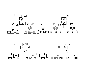
Figure 1 shows a schematic view of the layout of a device E for
control and/or monitoring of decentralized functional units
DFE1A to DFEnA, DFE1B to DFEnB etc. (also called element
controllers EC below) arranged along a railroad network (not
shown in greater
CA 02917091 2015-12-30
2013P12919W0
detail here). Should a specific functional unit not be meant, the
decentralized functional units will be referred to below by the
general designation DFE or EC. These types of decentralized
functional units DFE are used to control and to monitor train-
influencing and/or train-monitoring units. Signals, switches,
balises, line cables, track magnets and the like can be referred
to as train-influencing units for example. Balises and line
cables can likewise be referred to as train-monitoring units, as
can axle counters and track circuits. For example a signal S is
controlled and monitored by the decentralized functional unit
DFE1C. The decentralized functional unit DFE1C in such cases
controls the display of the signal terms and guides or assists in
monitoring functions respectively, such as the monitoring of the
lamp current in the signal for example.
Each decentralized functional unit DFE or the unit
controlled/monitored by it respectively has an address unique in
the overall network, for example an IP address or a MAC address.
The device E further includes a data transport network TN with a
number of network access points 2 to 16. Communication units 18
to 28 are connected to a part of these network access points 6 to
16. The data transport network TN is embodied as a high-
availability network here. Such high-availability structures can
be produced on the one hand by a redundant design of the network
itself and/or on the other hand by a clever re-organization of
the network on failure of a connecting piece.
The device E also comprises a superordinate control system 30
which, along with components not described in any greater detail
here, include a control center LT, an interlocking processor STW,
CA 02917091 2015-12-30
2013P12919W0
16
an axle count processor AZ and a service/diagnosis unit SD, which
are connected to the data transport network TN via the network
access points 2 and 4 by means of Ethernet connections.
As shown in Figure 1, the decentralized functional units DFE must
be coupled to the transport network TN by one of the
communication groups 18 to 28 and the corresponding network nodes
6 to 16 and can thus receive or interchange data telegrams via
said network. The decentralized functional units DFE are grouped
into subgroups A, 3, C, D and E, each with its own subnetwork NA,
NB, NC, ND and NE in such cases. The subgroup A is formed for
example from the decentralized functional units DFE1A, DFE2A,
DFE3A to DFEnA. In such cases the subgroups A to E are always
connected at their two ends to one of the communication groups 18
to 28 in each case and a network access point 6 to 16. Each
decentralized functional unit DFE also has an upstream switching
unit SU or SCU, which, as an alternative, can also be integrated
directly into the decentralized functional unit DFE, which
establishes the connection to the subnetwork for the
decentralized functional units DFE, so that each decentralized
functional unit DFE can still be addressed on failure of a
communication group by a second redundant communication group 18
to 28.
Each subnetwork (NA to NE) is thus constructed from a number of
point-to-point connections of logically-adjacent decentralized
functional units (DFE). In such cases a point-to-point connection
is embodied as an autonomous transmission link within the
subnetwork, for example as an ISDN transmission link or as an
xDSL transmission link or optical fiber transmission link. Thus
an individual subnetwork, which for its part only ever has to
CA 02917091 2015-12-30
2013P12919W0
17
deal with the transmission from point to point, can be
constructed so-to-speak from individual transmission cells. In
other words a much longer and more complex subnetwork can thus be
constructed from simple, rather short-range technologies. For
this reason it is expedient to terminate the point-to-point
connection at each end with a switching unit (SU), through which
the opportunity is even afforded to change the point-to-point
transmission technology from cell to cell and thus enable the
most suitable transmission technology to be chosen in each case.
A suitable switching unit (SU) can be designed for this purpose
so that it provides a number of point-to-point transmission
technologies and, depending on the circuitry, provides the point-
to-point transmission technology determined by the circuitry in a
self-organizing manner.
Furthermore the subgroups A to E are each connected to the two
communication groups 18 to 28 at a first connection type or a
second connection type. In the first connection type, such as is
shown for the subgroups A, C and E for example, the associated
subnetwork NA, NC und NE is terminated in two geographically
closely-located communication groups 18 and 20 or 22 and 24 or 26
and 28, which is to be shown in Figure 1 by the immediate
adjacency of the communication group pairs 18, 20 and 22, 24 and
26, 28. In the second connection type, as is shown for the
subgroups B and D, the respective subnetwork NB or ND will be
terminated with the spatially more widely spaced communication
groups 20, 22 or 24, 26. Here too, on failure of one of the two
associated communication groups, each subgroup B and D is then
still connected to a further communication group.
CA 029170912015-12-m
2013P12919W0
18
If it is now assumed that the network access points 6, 8 and 10,
12 and 14, 16 are each arranged at stations of the railroad
network, then the subgroups A, C and E tend to represent the
decentralized functional units DFE arranged in the station area.
The subgroups B and D tend to represent such decentralized
functional units DFE, as are arranged in the area between two
stations on open tracks. In such cases the widely-available
existing copper cables present in large numbers can possibly be
used for the coupling-in of these decentralized functional units
DFE, which will be explained using the subgroup B is an example.
Previously for example the decentralized functional units DFE1B,
DFE2B und DFE3B have been controlled from the station at network
access point 8. Accordingly the remaining decentralized network
access points DFEnB are controlled from the station at network
access point 10. Thus it was sufficient just to establish one
connection between the decentralized functional units DFE3B and
DFEnB in order to connect the subgroup B in the subnetwork NB
together.
The system boundaries of the device E can in this case be
described as follows:
- The number of network access points 2 to 16 on the transport
network OTN is only limited by the system performance
(interlocking computer STW, transport network OTN);
- The number of DFEs on a subnetwork A to E amounts to a minimum
of one DFE: the maximum number of connectable DFEs is limited by
the system performance (at least 8 DFEs might be desired for
example);
- The number of communication units 18 to 28 at a network access
point 6 to 16 is essentially limited by the maximum number of
CA 02917091 2015-12-30
2013P12919W0
19
Ethernet interfaces of the selected network access points 6 to
16.
- The maximum number of subnetworks A to E connectable to a
communication unit 18 to 28 can amount to four subnetworks in the
exemplary embodiment selected.
- to insure high availability it can be stated that one
subnetwork A to E must be connected to two communication units 18
to 28;
- The communication units 18 to 28 belonging to a subnetwork A
to E must be connected to two network access points; in such
cases the two network access points 2 to 16 can be connected to
the same transport network OTN or to two network access points of
two different transport networks (this case for the second
transport network OTN has not been shown here but is readily able
to be implemented technically).
In order to satisfy the performance requirements and be able to
work with simple transmission means such as e.g. ISDN, xDSL,
SHDSL, the telegrams can be subdivided into real-time and non¨
real-time telegrams within the subnetworks A to E:
- Real-time telegrams: payload data telegrams from the
interlocking to the DFEs as specific TCP/IP telegrams, specific
Ethernet frame type;
- Non-real-time telegrams: normal TCP/IP telegrams, no payload
data telegrams.
The telegram types have fixed timeslots assigned. The assignment
can be fixed during operation and be able to be parameterized
off-line, for example in a ratio of at least 1 to 10.
CA 02917091 2015-12-30
2013P12919W0
Figure 2 now shows a schematic diagram of the situation only
still applicable as regards data transmission with the inventive
energy supply concept in accordance with Figure 1. All element
controllers DFE, EC are now connected to the same data transport
network ETN. The electrical energy is now no longer supplied from
the central interlocking but is supplied via intelligent energy
injection nodes IEK, which have no relationship to the data
processing actions of the element controllers EC. Intelligent
energy stores IES1 to IES5 are now connected to the energy
transport network ETN at suitable positions of the energy
transport network ETN, so that these intelligent energy stores
IES1 to IES5 can undertake data communication via the data
transport network TN with the central interlocking STW and thus
power can be accepted and/or output in a controlled manner via an
energy manager IEM implemented in the logic of the central
interlocking STW.
The energy needed in the energy transport network ETN is provided
in this case to the two intelligent energy injection nodes IEK
shown here by two energy backbones EB1 and EB2 independent of one
another. In this present case the energy backbone 1 is the public
uninterruptible power supply network (local network). The energy
backbone EB2 is supplied from the catenary wire of the railroad
network, wherein the power supply for the catenary wire is a
proprietary structure of the railroad operator, which for this
purpose has its own power plants independent of the public power
supply network. In the variant a) shown in Figure 2 the element
controllers EC are each supplied, combined into groups, by one
intelligent energy store IES1 to IES5. In the variant b) shown
the energy transport network ETN forms an energy bus extending
from the one intelligent energy injection node to the other
CA 02917091 2015-12-30
2013P12919W0
21
intelligent energy injection node IEK, to which the element
controllers EC and the intelligent energy stores IES each couple
independently.
Figure 3 now shows a second variant for an energy transport
network ETN, in which two redundantly embodied energy backbones
EB1 and EB2 are provided. In this figure the energy transport
network ETN is designed in the form of a bus between two
intelligent energy injection nodes IEK, wherein one intelligent
energy injection node is supplied by the first energy backbone
EB1 and the other intelligent energy injection node is supplied
by the second energy backbone EB2. Part a) again shows the
element controllers EC coupling in groups to an intelligent
energy store IES. Part b) again includes the individual
connection of the element controllers EC and the intelligent
energy stores to the energy transport network ETN. In the final
analysis the configuration of the intelligent energy injection
nodes IEK depends on the hierarchical structure of the energy
backbone provided. If for example, during a blackout of the local
network, there is an outage of two neighboring stations, then it
is sensible to connect the other energy backbone to one of the
two stations in each case.
Figure 4 shows a slightly modified variant by comparison with
Figure 2, in which only the intelligent energy injection nodes
IEK are attached to the energy backbones EB1 and EB2 in each
case.
Figure 5 now shows schematically the connection of an element
controller EC to the data transport network OTN or the energy
supply network ETN in terms of data processing and energy supply.
CA 02917091 2015-12-30
2013P12919W0
22
Such a connection point comprises a communication unit SCU for
interchange of data via both branches of the data transport
network OTN. On the energy side a network node unit SND is
provided which couples to both branches of the energy transport
network ETN. The network node unit SND controls and supervises
the energy bus, detects excess currents within the bas and in
connected consumers (SPU with EC). It also supplies the
communication unit SCU with power and can also interchange data
with said unit via an Ethernet connection and is thus linked into
the Sinet network (e.g. activation of manual operation of the SND
via remote operation and actuation of the energy switch, output
of diagnostic data to the superordinate service and diagnosis
system, interrogating the current voltages, currents, energy and
power values, parameterization of the SND, data for charging an
energy store or notification of a future power requirement). A
supply unit SPU couples to the network node unit SND, which
converts the voltage of the transport network to the input
voltage required for the EC. In addition a data connection is
provided between the network node unit SND and the supply unit
SPU, e.g. in the form of a serial RS 422. A typical connection
here in energy terms for example is a three-phase connection with
400 VAC. Here in Figure 5 the element controller EC controls and
supplies the switch W. In this figure the element controller EC
receives data telegrams from superordinate interlocking computers
via an Ethernet connection from the communication unit SCU and
outputs the acknowledgements to the interlocking computer via
this SCU.
In the way shown here it is possible to supply the energy
transport network ETN with the required electrical power at any
time, wherein the independence of the two energy backbones EB1,
CA 02917091 2015-12-30
2013P12919W0
23
E52 is a guarantee that, should one energy backbone fail, at
least the other energy backbone remains intact, which guarantees
a supply security of almost 100%. An energy backbone is
considered to be the public supply network for example (with
Swissgrid AG as the operator in Switzerland for example). Another
energy backbone can be the proprietary railroad power system
(catenary/overhead wire) of the railroad infrastructure operator,
which for example with Swiss national railways in Switzerland,
maintains its own power stations to supply the energy required
for the railroad system and can thus operate independently of the
public power supply network.