Note : Les descriptions sont présentées dans la langue officielle dans laquelle elles ont été soumises.
CA 02918882 2016-01-21
SPECIFICATION
TITLE OF THE INVENTION
COATED PARTICLES, INJECTION MATERIAL AND PACKING
METHOD
TECHNICAL FIELD
[0001] The present invention relates to coated
particles, an injection material and a packing method.
RELATED ART
[0002] Recently, recovery of oily hydrocarbon or
gaseous hydrocarbon (a fluid) from a subterranean
formation is positively carried out. In particular, a
wellbore is formed so as to penetrate the subterranean
formation (a shale layer) containing the hydrocarbon,
and then the hydrocarbon is recovered through the
wellbore. In this case, the subterranean formation is
required to have sufficient fluid permeability
(conductivity) to allow the fluid to flow into the
wellbore.
[0003] In order to ensure the fluid permeability of
the subterranean formation, for example, hydraulic
fracturing is carried out. In the hydraulic fracturing
operations, a viscous liquid is first injected into the
subterranean formation through the wellbore at a
sufficient rate and pressure to thereby form fractures
(cracks) in the subterranean formation. After that, an
injection material containing particles is injected
into the subterranean formation to pack the particles
in the formed fractures for the purpose of preventing
the fractures from being closed (blocked).
[0004] As such particles, coated particles, which
are obtained by coating core particles such as silica
1
CA 02918882 2016-01-21
sand or glass beads with a thermosetting resin such as
an epoxy resin or a phenol resin, are well known (see
Patent documents 1 and 2).
[0005] Since such core particles of the coated
particles are coated with the resin, even if the core
particles are collapsed into pieces due to the pressure
of the ground, it is possible to prevent the pieces
thereof from being scattered (spread). This makes it
possible to prevent spaces among the coated particles
from being closed by the above pieces to thereby
maintain the fluid permeability of the subterranean
formation.
[0006] However, from the viewpoint of improving an
amount of the hydrocarbon to be recovered from the
subterranean formation, it is required to develop
coated particles which can maintain higher fluid
permeability of the subterranean formation.
PRIOR ART DOCUMENT
PATENT DOCUMENT
[0007] Patent document 1: USP No. 3,935,339
Patent document 2: USP No. 4,336,842
SUMMARY OF THE INVENTION
PROBLEM TO BE SOLVED BY THE INVENTION
[0008] It is an object of the present invention to
provide coated particles adapted to be packed in
fractures formed in a subterranean formation and
capable of maintaining high fluid permeability thereof,
an injection material containing the coated particles,
and a packing method for injecting such an injection
material into the fractures.
MEANS FOR SOLVING PROBLEM
2
CA 02918882 2016-01-21
[0009] In order to achieve the object, the present
invention includes the following features (1) to (21).
(1) Coated particles adapted to be packed in
fractures formed in a subterranean formation, each of
the coated particles comprising:
a core particle having an outer surface; and
a surface layer coating at least a part of the
outer surface of the core particle,
wherein the surface layer contains an acid curing
agent and an acid curable resin to be cured in the
presence of an acid, and
wherein the acid curing agent is composed of
acidic compounds having acidic groups, and at least a
part of the acidic groups of the acidic compounds are
blocked by block compounds having reactivity with the
acidic groups.
[0010] (2) The coated particles according to the
above feature (1), wherein the block compounds have
functional groups, and the functional groups are
chemically bonded to the acidic groups of the acidic
compounds so that the acidic compounds are blocked.
[0011] (3) The coated particles according to the
above feature (2), wherein the functional groups of the
block compounds include at least one selected from the
group consisting of a hydroxyl group and an amino
group.
[0012] (4) The coated particles according to the
above feature (2) or (3), wherein the block compounds
include an alkyl alcohol having a hydroxyl group as the
functional group.
[0013] (5) The coated particles according to the
above feature (4), wherein the alkyl alcohol is a
3
CA 02918882 2016-01-21
monovalent alkyl alcohol.
[0014] (6) The coated particles according to the
above feature (2) or (3), wherein the block compounds
include an alkyl amine having an amino group as the
functional group.
[0015] (7) The coated particles according to any
one of the above features (2) to (6), wherein in the
case where the number of the acidic groups of the acid
curing agent is defined as "1 (one)", the block
compounds are contained in the surface layer so that
the number of the functional groups thereof is in the
range of 0.1 to 1.9.
[0016] (8) The coated particles according to any
one of the above features (1) to (7), wherein the
acidic groups of the acidic compounds include a
sulfonic acid group.
[0017] (9) The coated particles according to the
above feature (8), wherein the acidic compounds include
at least one selected from the group consisting of p-
toluene sulfonic acid, benzene sulfonic acid, dodecyl
benzene sulfonic acid, phenol sulfonic acid,
naphthalene sulfonic acid, dinonyl naphthalene sulfonic
acid and dinonyl naphthalene disulfonic acid.
[0018] (10) The coated particles according to any
one of the above features (1) to (9), wherein an amount
of the acid curing agent contained in the surface layer
is in the range of 0.1 to 20 parts by mass with respect
to 100 parts by mass of the acid curable resin.
[0019] (11) The coated particles according to any
one of the above features (1) to (10), wherein the acid
4
CA 02918882 2016-01-21
curable resin is cured at a temperature of 100 C or
lower due to the action of the acidic compounds.
[0020] (12) The coated particles according to any
one of the above features (1) to (11), wherein the acid
curable resin includes at least one selected from the
group consisting of a flan resin and a phenol resin.
[0021] (13) The coated particles according to any
one of the above features (1) to (12), wherein the acid
curable resin is in a cured state, a semicured state or
an uncured state.
[0022] (14) The coated particles according to any
one of the above features (1) to (13), wherein an
average thickness of the surface layer is in the range
of 0.5 to 20 pm.
[0023] (15) The coated particles according to any
one of the above features (1) to (14), wherein the
surface layer coats 50 to 100% of the outer surface of
the core particle.
[0024] (16) The coated particles according to any
one of the above features (1) to (15), wherein the core
particles include at least one kind of sand particles
and ceramics particles.
[0025] (17) The coated particles according to any
one of the above features (1) to (16), wherein an
average particle size of the core particles is in the
range of 100 to 3,000 pm.
[0026] (18) An injection material adapted to be
injected into fractures formed in a subterranean
formation, the injection material comprising:
CA 02918882 2016-01-21
,
the coated particles defined by any one of the
above features (1) to (17); and
a fluid which disperses the coated particles
therein and transfers the coated particles to the
fractures.
[0027] (19) The injection material according to the
above feature (18), wherein the fluid includes at least
one of a solvent, a viscosity modifier, a surfactant, a
breaker, a viscosity stabilizer, a gelling agent and a
stabilizer.
[0028] (20) The injection material according to the
above feature (18) or (19), wherein an amount of the
coated particles contained in the injection material is
in the range of 1 to 99 wt%.
[0029] (21) A packing method for packing particles
in fractures formed in a subterranean formation by
transferring the injection material defined by any one
of the above features (18) to (20) to the fractures
through a wellbore penetrating the subterranean
formation to inject the injection material into the
fractures.
EFFECTS OF THE INVENTION
[0030] According to the present invention, out of
the acid curing agent and the acid curable resin
contained in the surface layers of the coated
particles, at least a part of the acidic groups of the
acidic compounds composing the acid curing agent are
blocked by, for example, being chemically bonded to the
block compounds having the reactivity with the acidic
groups. Therefore, it is prevented that the acidic
compounds affect the acid curable resin at an
unrequired place. This makes it possible to reliably
6
CA 02918882 2016-01-21
cure the acid curable resin at a required place. As a
result, when the coated particles are injected into
packed spaces (the fractures of the subterranean
formation), it is possible to effectively suppress or
prevent the coated particles from being collapsed to
thereby improve fluid permeability of the packed spaces
in which the coated particles are packed.
BRIEF DESCRIPTION OF THE DRAWINGS
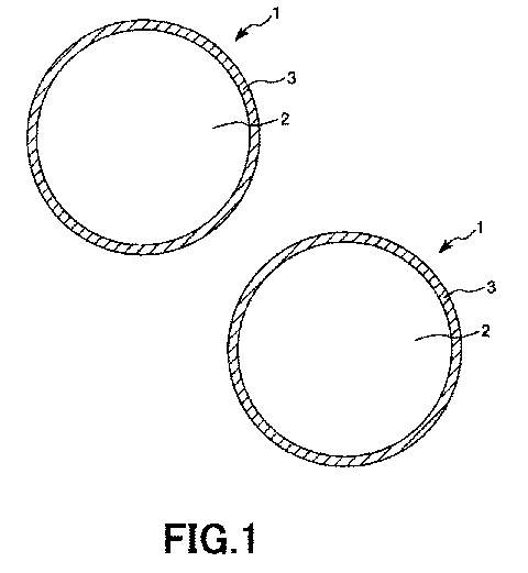
[0031] FIG. 1 is a partial cross-sectional view
showing an embodiment of coated particles according to
the present invention.
FIG. 2 is a partial cross-sectional view showing
a state that pressure is imparted to the coated
particles shown in FIG. 1.
FIG. 3 is a conceptual view for explaining a
method for recovering hydrocarbon from a subterranean
formation.
FIG. 4 is a view for explaining a method for
measuring fluid permeability.
MODE FOR CARRING OUT THE INVENTION
[0032] Hereinafter, preferred embodiments of coated
particles, an injection material and a packing method
according to the present invention will be described in
detail with reference to the accompanying drawings.
[0033] FIG. 1 is a partial cross-sectional view
showing an embodiment of the coated particles according
to the present invention, and FIG. 2 is a partial
cross-sectional view showing a state that pressure is
imparted to the coated particles shown in FIG. 1.
[0034] The coated particles of the present
invention are packed in fractures formed in a
subterranean formation to prevent closure of the
7
CA 02918882 2016-01-21
fractures and maintain fluid permeability of packed
spaces of the subterranean formation in which the
coated particles are packed (the fractures of the
subterranean formation). This makes it possible to
improve a flowing rate of hydrocarbon (a shale gas or a
shale oil) contained in the subterranean formation into
a wellbore formed so as to penetrate the subterranean
formation.
[0035] As shown in FIG. 1, each coated particle 1
includes a core particle 2 and a surface layer 3
coating at least a part of an outer surface of the core
particle 2.
[0036] The core particles 2 serve as a propping
agent in the fractures when the coated particles 1 are
packed in the fractures.
As the core particles 2, various kinds of
particles having relatively high mechanical strength
can be used. The core particles 2 are not limited to a
specific kind. Concrete examples of the core particles
2 include sand particles, ceramics particles, silica
particles, metal particles, organic particles, and the
like.
[0037] Among them, it is preferred that the core
particles 2 include at least one kind of the sand
particles and the ceramics particles. The sand
particles and the ceramics particles have high
mechanical strength and can be easily obtained at
relatively low cost.
[0038] An average particle size of the core
particles 2 is preferably in the range of about 100 to
3,000 pm, and more preferably in the range of about 200
to 1,000 pm. By using the core particles 2 having such
8
CA 02918882 2016-01-21
an average particle size, it is possible to prevent
aggregation of the resulting coated particles 1.
Further, it is also possible to sufficiently maintain
the fluid permeability of the fractures in which the
coated particles 1 are packed.
[0039] In this
regard, the core particles 2 may
have variations in the particle size, and may contain
one kind and another kind having about 10 times larger
particle size than that of the one kind. Namely, when
a size distribution of the core particles 2 is
measured, a half width of a peak of a size distribution
curve shown as a chevron function may be a relatively
large value.
[0040] In FIG. 1, a
cross-sectional shape of the
core particle 2 is depicted as a substantially circular
shape, but may be an ellipsoidal shape, a polygonal
shape, an irregular shape or the like. In this case,
the particle size of the core particle 2 is defined as
a maximum length in a cross-sectional shape thereof.
[0041] In the case
where the ceramics particles are
used as the core particles 2, it is preferred that each
ceramics particle has a nearly circular shape as
possible in the cross-sectional shape thereof. Such
ceramics particles have especially high mechanical
strength. Further, by
manufacturing the coated
particles 1 with such ceramics particles, it is
possible to increase sphericity of the resulting coated
particles 1. As a result, contacts among the coated
particles 1 become point contacts when the coated
particles 1 are packed in the fractures. This makes it
possible to increase volumes of spaces (channels)
created among the coated particles 1.
9
CA 02918882 2016-01-21
[0042] Further, natural sand particles may be
directly used as the core particles 2. By using such
sand particles as the core particles 2, it is possible
to improve productivity of the injection material and
save cost thereof. Furthermore, a mixture of the
ceramics particles and the sand particles may be used
as the core particles 2. In this case, a mixing ratio
of the ceramics particles to the sand particles is
preferably in the range of about 1:9 to 9:1, and more
preferably in the range of about 3:7 to 7:3 in a mass
ratio.
[0043] At least a part of the outer surface of each
core particle 2 is coated with the surface layer 3.
Even if the coated particles 1 packed in the fractures
of the subterranean formation are collapsed into pieces
due to the pressure of the ground, this surface layer 3
can operate to prevent the pieces of the core particles
2 from being scattered (spread) as shown in FIG. 2.
For this reason, it is possible to prevent the spaces
(channels) among the coated particles 1 from being
closed by the pieces of the core particles 2. This
makes it possible to more reliably maintain the fluid
permeability of the fractures in which the coated
particles 1 are packed.
[0044] The surface layer 3 preferably coats the
entire outer surface of each core particle 2. However,
the surface layer 3 may coat only a part of the outer
surface of each core particle 2 as long as it prevents
the pieces of the core particles 2 from being scattered
even if the core particles 2 are collapsed into the
pieces due to the pressure of the ground. For the
reasons stated above, the surface layer 3 preferably
coats 50 to 100% of the outer surface of each core
particle 2, more preferably coats 70 to 100% thereof,
CA 02918882 2016-01-21
and even more preferably coats 90 to 100% thereof.
[0045] Further, an average thickness of the surface
layer 3 is not limited to a specific value, but is
preferably in the range of 0.5 to 20 pm, and more
preferably in the range of 1 to 10 pm. By setting the
average thickness of the surface layer 3 to a value
falling within the above range, it is possible to
sufficiently provide a scattering prevention effect of
the pieces of the core particles 2, while preventing
the sizes of the coated particles 1 from becoming large
more than necessary.
[0046] Such a surface layer 3 contains an acid
curing agent composed of acidic compounds of which at
least a part of acidic groups are blocked, and an acid
curable resin to be cured in the presence of an acid,
that is, due to the action of the acidic compounds. By
curing the acid curable resin due to the action of the
acidic compounds, it is possible to impart high
mechanical strength to the surface layer 3, and to
reliably prevent the pieces of the core particles 2
from being scattered even if the core particles 2 are
collapsed into the pieces.
[0047] In this regard, the acid curable resin has
only to be cured in a state that the coated particles 1
are packed in the fractures of the subterranean
formation.
[0048] Thus, the acid curable resin may be in
either a cured state, a semicured state or an uncured
state before the coated particles 1 are packed in the
fractures. In the case where the acid curable resin is
in the semicured state or the uncured state, it is
cured due to the action of the acidic compounds under
11
CA 02918882 2016-01-21
the conditions of the heat and pressure of the ground
when the coated particles 1 are packed in the fractures
of the subterranean formation.
[0049] Hereinafter, description will be made on a
process in which the acidic compounds and the acid
curable resin are reacted with each other to cure the
acid curable resin.
[0050] According to the present invention, in this
surface layer 3, at least a part of the acidic groups
of the acidic compounds, which has reactivity with the
acid curable resin, are blocked by being chemically
bonded to block compounds having reactivity with the
acidic groups. Further, the block compounds are
designed so as to be eliminated from the acidic
compounds under the predetermined conditions.
[0051] Here, in the case where the acid curable
resin is in the cured state before the coated particles
1 are packed in the fractures, the block compounds are
eliminated from a lot of the acidic compounds contained
in the surface layer 3. In contrast, in the case where
the acid curable resin is in the semicured state or the
uncured state before the coated particles 1 are packed
in the fractures, the block compounds are blocking the
acidic compounds by chemically bonding to the acidic
groups of the acidic compounds without being eliminated
from the majority of the acidic compounds contained in
the surface layer 3.
[0052] Therefore, it is possible to suppress or
prevent the acidic compounds and the acid curable resin
from being contacted (reacted) with each other to
thereby cure the acid curable resin at an unrequired
place. In contrast, the acidic compounds and the acid
12
CA 02918882 2016-01-21
curable resin can be contacted (reacted) with each
other by eliminating the block compounds from the
acidic compounds at a required place (that is, the
fractures formed in the subterranean formation) to
thereby cure the acid curable resin. In other words,
the acidic compounds lose the function (reactivity) of
curing the acid curable resin by being blocked by the
block compounds at the unrequired place, but can cure
the acid curable resin by activating the above function
due to the elimination of the block compounds at the
required place.
[0053] In this way, the acid curable resin can be
selectively cured at the required place (that is, the
fractures formed in the subterranean formation) to
thereby improve the strength of the surface layer 3.
This makes it possible to more reliably maintain the
fluid permeability of the packed spaces of the
subterranean formation in which the coated particles 1
are packed. Therefore, it is possible to improve the
flowing rate of the hydrocarbon into the wellbore
communicating with the fractures.
[0054] In this regard, in this specification,
"blocking" means that the functional groups of the
block compounds are chemically bonded to the acidic
groups of the acidic compounds to inactivate reactivity
of progressing the curing of the acid curable resin by
the acidic groups (reactivity with the acid curable
resin). Further, "releasing of blocking" means that
the functional groups of the block compounds are
eliminated from the acidic groups of the acidic
compounds to activate the reactivity of progressing the
curing of the acid curable resin by the acidic groups.
[0055] Further, "chemical bond" has only to
13
CA 02918882 2016-01-21
inactivate the reactivity of progressing the curing of
the acid curable resin due to the reaction of the
acidic groups of the acidic compounds with the
functional groups of the block compounds, and examples
thereof include an intramolecular bond such as a
covalent bond or a coordinate bond, and a chemical bond
between molecules such as an ionic bond or a Van der
Waals bond.
[0056] The acidic compounds serve as a catalyst for
promoting the curing reaction of the acid curable resin
when they make contact with the acid curable resin
after the blocking thereof by the block compounds is
released.
[0057] Such acidic compounds may be any compounds
as long as they have the acidic groups, and thus can
exhibit the function as the catalyst by the action of
the acidic groups. Concrete examples of the acidic
compounds include: compounds having sulfonic acid
groups as the acidic groups such as p-toluene sulfonic
acid, benzene sulfonic acid, dodecyl benzene sulfonic
acid, phenol sulfonic acid, naphthalene sulfonic acid,
dinonyl naphthalene sulfonic acid, dinonyl naphthalene
disulfonic acid, xylene sulfonic acid and methane
sulfonic acid; compounds having carboxyl groups as the
acidic groups such as acetic acid, lactic acid, maleic
acid, benzoic acid and fluoroacetic acid; and the like.
One of them can be used or to or more of them can be
used in combination.
[0058] Among them, it is preferred that the acidic
compounds are the compounds having the sulfonic acid
groups as the acidic groups. Such compounds having the
sulfonic acid groups as the acidic groups are a very
good catalyst for the acid curable resin, and the
14
CA 02918882 2016-01-21
acidic groups thereof can be reliably blocked by the
block compounds.
[0059] Further, it is preferred that the compounds
having the sulfonic acid groups as the acidic groups
contain at least one selected from the group consisting
of the p-toluene sulfonic acid, the benzene sulfonic
acid, the dodecyl benzene sulfonic acid, the phenol
sulfonic acid, the naphthalene sulfonic acid, the
dinonyl naphthalene sulfonic acid and the dinonyl
naphthalene disulfonic acid. The acidic groups of
these acidic compounds can be more reliably blocked by
the block compounds.
[0060] An amount of the acid curing agent contained
in the surface layer 3 is preferably in the range of
about 0.1 to 20 parts by mass, more preferably in the
range of about 0.5 to 15 parts by mass, and even more
preferably in the range of about 1 to 10 parts by mass
with respect to 100 parts by mass of the acid curable
resin contained in the surface layer 3. By setting the
amount of the acid curing agent contained in the
surface layer 3 to a value falling within the above
range, in the case where the blocking of the acidic
compounds is released to cure the acid curable resin by
the action thereof, even if the blocking of about half
of the acidic compounds by the block compounds is not
released with some causes, it is possible to secure a
sufficient amount of the acidic compounds by which the
acid curable resin can be cured.
[0061] The block compounds having reactivity with
the acidic groups of the acidic compounds block the
acidic groups of the acidic compounds. Therefore, in
the case where the acid curable resin is in the
semicured state or the uncured state before the coated
CA 02918882 2016-01-21
particles 1 are packed in the fractures, the block
compounds have a function of suppressing or preventing
the acidic compounds and the acid curable resin from
being reacted with each other to cure the acid curable
resin at the unrequired place. On the other hand, the
block compounds also have a function of reacting the
acidic compounds and the acid curable resin with each
other by being eliminated from the acidic compounds to
cure the acid curable resin at the required place.
[0062] Such block compounds have the functional
groups, and the functional groups are chemically bonded
to the acidic groups of the acidic compounds to block
the acidic compounds.
[0063] The functional groups may be any groups
which are reacted with the acidic groups so that the
block compounds can be connected (chemically bonded) to
the acidic compounds. Specifically, examples of the
functional groups include at least one selected from a
hydroxyl group, an amino group and the like. Such
block compounds having the functional groups exhibit
excellent reactivity with the acidic groups of the
=
acidic compounds. Therefore, the acidic compounds can
be reliably blocked by the block compounds due to the
reaction (the chemical bond) between the functional
groups and the acidic groups.
[0064] Examples of the block compounds having the
hydroxyl groups as the functional groups include
alcohols and phenols. Examples of the alcohols include
an alkyl alcohol such as a monovalent alkyl alcohol or
a polyvalent alkyl alcohol, an alkenyl alcohol, an
aromatic alcohol, a heteroring-containing alcohol, and
the like. Among them, it is preferred that the block
compounds having the hydroxyl groups include the alkyl
16
CA 02918882 2016-01-21
alcohol. This makes it possible to more reliably block
the acidic compounds by the block compounds.
[0065] Further, the
monovalent alkyl alcohol may be
either a monovalent alkyl alcohol having a linear alkyl
group (a linear monovalent alkyl alcohol), a monovalent
alkyl alcohol having a branch alkyl group (a branch
monovalent alkyl alcohol), or a monovalent alkyl
alcohol having a cyclic alkyl group (a cyclic
monovalent alkyl alcohol).
[0066]
Specifically, examples of the linear or
branch monovalent alkyl alcohol include: methanol;
ethanol; propanol such as 1-propanol or 2-propanol;
butanol such as 1-butanol, 2-butanol, 2-methyl-l-
propanol or 2-methy1-2-propanol; pentanol such as 1-
pentanol, 2-pentanol, 3-pentanol, 2-methyl-l-butanol,
3-methyl-l-butanol, 2-methyl-2-butanol or 2,2-dimethyl-
1-propanol; hexanol such as 1-hexanol, 2-hexanol, 3-
hexanol, 2-methyl-l-pentanol, 2-methyl-2-pentanol, 2-
methy1-3-pentanol, 3-methyl-l-pentanol, 3-methy1-2-
pentanol, 3-methyl-3-pentanol, 4-methyl-l-pentanol, 4-
methyl-l-pentanol, 4-methyl-2-pentanol, 2,3-dimethy1-2-
butanol, 3,3-dimethy1-2-butanol, 2-ethyl-l-
butanol;
heptanol such as 1-heptanol, 2-heptanol, 3-heptanol, 2-
methyl-l-hexanol, 2-methyl-2-hexanol, 2-methy1-3-
hexanol, 5-methyl-2-hexanol, 3-ethyl-3-pentanol, 2,2-
dimethy1-3-pentanol, 2,4-dimethy1-3-pentanol, 4,4-
dimethy1-2-pentanol or 3-methyl-1-hexanol; octanol such
as 1-octanol, 2-octanol, 3-octanol, 4-methy1-3-
heptanol, 6-methyl-2-heptanol, 2-ethyl-l-hexanol, 2-
propyl-l-pentanol, 2-methyl-l-heptanol, 2,2-dimethyl-l-
hexanol; nonanol such as 1-nonanol, 2-nonanol, 3,5,5-
trimethyl-l-hexanol, 2,6-dimethy1-4-heptanol, 3-ethyl-
2,2-dimethy1-3-pentanol; decanol such as 1-decanol, 2-
decanol, 4-decanol, 3,7-dimethyl-l-octanol, 2,4,6-
17
CA 02918882 2016-01-21
trimethyl heptanol; undecanol; dodecanol; tridecanol;
tetradecanol; heptadecanol; octadecanol such as
heptadecanol; nonadecanol; eicosanol; heneicosanol;
tricosanol; tetracosanol; and the like. One of them
can be used or two or more of them can be used in
combination.
[0067] Further,
examples of the cyclic monovalent
alkyl alcohol (cycloalkyl alcohol) include:
cyclopentanol; cycloheptanol; methyl cyclopentanol;
cyclopentyl methanol; cyclohexyl methanol; 1-cyclohexyl
ethanol; 2-cyclohexyl ethanol; 3-cyclohexyl propanol;
4-cyclohexyl butanol; cyclohexanols such
as
cyclohexanol, methyl cyclohexanol, dimethyl
cyclohexanol, tetramethyl cyclohexanol, hydroxy
cyclohexanol, (1S,2R,5S)-2-
isopropyl-5-methyl
cyclohexanol, butyl cyclohexanol and 4-t-butyl
cyclohexanol; and the like. One of them can be used or
two or more of them can be used in combination.
[0068] Furthermore,
examples of the polyvalent
alkyl alcohol include a divalent alcohol such as
ethylene glycol (1,2-ethanediol), 1,2-propanediol or
1,3-propanediol, a trivalent alcohol such as glycerin,
a tetravalent alcohol such as pentaerythritol, and the
like. One of them can be used or two or more of them .
can be used in combination.
[0069] In this
regard, in the case where the acidic
compounds having the sulfonic acid groups as the acidic
groups are used, they are reacted with the block
compounds having the hydroxyl groups as the functional
groups to thereby form sulfonic acid ester bonds. In
this way, the acidic compounds are blocked by the block
compounds. Namely, sulfonic acid esters are produced
as the acidic compounds of which the acidic groups are
18
CA 02918882 2016-01-21
blocked by the block compounds.
[0070] On the other
hand, examples of the block
compounds having the amino groups as the functional
groups include: an alkyl amine such as a monovalent
alkyl amine or a polyvalent alkyl amine; an alkenyl
amine; an aromatic amine; a heteroring-containing
amine; and the like. Among them, it is preferred that
the block compounds having the amino groups include the
alkyl amine. This makes it possible to more reliably
block the acidic compounds by the block compounds.
[0071] Further,
examples of the monovalent alkyl
amine include: a monoalkyl amine such as hexyl amine,
heptyl amine, octyl amine, nonyl amine, decyl amine,
undecyl amine, dodecyl amine, tridecyl amine,
tetradecyl amine, pentadecyl amine, hexadecyl amine,
octadecyl amine, isopropyl amine, isoamyl amine or 3,3-
dimethyl butyl amine; a dialkyl amine such as N-ethyl
butyl amine, dibutyl amine, dipentyl amine, dihexyl
amine, diheptyl amine, dioctyl amine, dinonyl amine,
didecyl amine, N-methyl cyclohexyl amine or
dicyclohexyl amine; a trialkyl amine such as trimethyl
amine, triethyl amine, tripropyl amine, tributyl amine
or trioctyl amine; and the like. One of them can be
used or two or more of them can be used in combination.
[0072] Furthermore,
examples of the polyvalent
alkyl amine include: a diamine such as ethylene
diamine, hexamethylene diamine, diethylene triamine,
triethylene tetramine, tetraethylene pentamine or
pentaethylene hexamine; a triamine such as
bis(hexamethylene) triamine; and the like. One of them
can be used or two or more of them can be used in
combination.
19
CA 02918882 2016-01-21
[0073] In this regard, in the case where the acidic
compounds having the sulfonic acid groups as the acidic
groups are used, they are reacted with the block
compounds having the basic amine groups as the
functional groups to thereby form salts by
neutralization (ionic bonds). In this way, the acidic
compounds are blocked by the block compounds. Namely,
sulfonic acid amine salts are produced as the acidic
compounds of which the acidic groups are blocked by the
block compounds.
[0074] Further, in the case where the number of the
acidic groups of the acid curing agent is defined as "1
(one)", the block compounds are contained in the
surface layer 3 so that the number of the functional
groups thereof is preferably in the range of 0.1 to
1.9, more preferably in the range of 0.3 to 1.7, and
even more preferably in the range of 0.5 to 1.5.
[0075] In this regard, a method for producing the
acidic compounds of which the acidic groups are blocked
by the block compounds is not limited to a specific
method. In the case where the acidic compounds are
carboxylic acids having carboxyl groups, and the block
compounds are alcohols or phenols having hydroxyl
groups, for example, the carboxylic acids and the
alcohols or phenols are mixed with each other, and then
heated by using concentrated sulfuric acid or the like
as a catalyst so that a dehydration condensation
reaction therebetween occurs. In this way, it is
possible to produce carboxylic acid esters which are
the acidic compounds of which the acidic groups are
blocked.
[0076] Further, in the case where the acidic
compounds are sulfonic acids having sulfonic acid
CA 02918882 2016-01-21
groups, and the block compounds are the alcohols or
phenols having the hydroxyl groups, for example,
sulfonic acid chlorides and the alcohols or phenols are
reacted with each other by using pyridine as a solvent.
In this way, it is possible to produce sulfonic acid
esters which are the acidic compounds of which the
acidic groups are blocked.
[0077] On the other hand, in the case where the
acidic compounds are the carboxylic acids having the
carboxyl groups or the sulfonic acids having the
sulfonic acid groups, and the block compounds are
amines having amine groups, for example, the carboxylic
acids or sulfonic acids and the amines are mixed with
each other while being heated so that a neutralization
reaction therebetween occurs. In this way, it is
possible to produce sulfonic acid salts or carboxylic
acid salts which are the acidic compounds of which the
acidic groups are blocked.
[0078] Further, examples of the acid curable resin
include a furan resin, a phenol resin, a melamine
resin, a urea resin, an oxetane resin, and the like.
One of them can be used or two or more of them can be
used in combination. Among them, it is preferred that
the acid curable resin includes at least one selected
from the group consisting of the flan resin and the
phenol resin. Since such an acid curable resin is
easily cured at about room temperature in the presence
of an acid such as the acidic compounds (the acidic
groups of the acidic compounds), it is especially
appropriate to use in the present invention.
Furthermore, by using such a resin, it is possible to
impart especially high mechanical strength to the
surface layer 3.
21
CA 02918882 2016-01-21
[0079] Examples of the furan resin include a
furfural resin, a furfural phenol resin, a furfural
ketone resin, a furfuryl alcohol resin, a furfuryl
alcohol phenol resin, and the like.
[0080] Examples of the phenol resin include a
resol-type phenol resin, an alkylene etherified resol-
type phenol resin, a dimethylene ether-type phenol
resin, an aminomethyl-type phenol resin, a novolac-type
phenol resin, an aralkyl-type phenol resin, a
dicyclopentadiene-type phenol resin, and the like.
[0081] Further, in the coated particles 1 each
having the above configuration, the acid curable resin
is cured at a temperatures of preferably 100 C or
lower, more preferably 75 C or lower, and even more
preferably 25 C (room temperature) or lower by the
action of the acidic compounds which are not blocked by
the block compounds (unblocked forms of the acidic
compounds). By selecting such an acid curable resin,
the coated particles 1 can be especially appropriately
used in the case where the hydrocarbon is collected
from a subterranean formation located at a relatively
shallow place by using the injection material
containing the coated particles 1.
[0082] As described above, even if the acid curable
resin is cured by the action of the acidic compounds at
a relatively low temperature, in such an injection
material, out of the acid curing agent and the acid
curable resin, at least a part of the acidic groups of
the acidic compounds composing the acid curing agent
are blocked by the block compounds. Therefore, before
the block compounds are eliminated from the acidic
compounds, it is possible to appropriately suppress or
prevent the acid curable resin from being cured.
22
CA 02918882 2016-01-21
[0083] In this regard, the acidic groups of almost
all acidic compounds are preferably blocked by the
block compounds, but the acidic groups of only a part
(e.g., preferably 60% or more, more preferably 75% or
more, and even more preferably 90% or more) of the
acidic compounds may be blocked by the block compounds.
[0084] The surface layer 3 may further contain
components other than the above mentioned components
such as the acid curing agent and the acid curable
resin.
[0085] Examples of the other components include a
lubricant (wax), a coupling agent, a toughening agent,
and the like. For example, the lubricant has a
function of improving conformability between the fluid
and the resin (the surface layer 3), and the coupling
agent has a function of improving adhesiveness between
the core particle 2 and the surface layer 3.
[0086] Examples of the lubricant include ethylene
bisstearic acid amide, methylene bisstearic acid amide,
oxystearic acid amide, stearic acid amide, methylol
stearic acid amide, hydrocarbon wax, stearic acid, and
the like. On the other hand, examples of the coupling
agent include a silane coupling agent such as
aminosilanee, epoxysilane or vinylsilane, a titanate
coupling agent, and the like.
[0087] In this regard, according to this embodiment
shown in FIG. 1, the surface layer 3 is depicted so as
to directly make contact with the core particle 2.
However, at least one intermediate layer having an
arbitrary function may be provided between the core
particle 2 and the surface layer 3. Examples of such a
23
CA 02918882 2016-01-21
function of the intermediate layer include a function
of improving adhesiveness between the core particle 2
and the surface layer 3, and the like.
[0088] The above mentioned coated particles 1 can
be manufactured by using manufacturing methods of
coated particles I to III described below.
[0089] First, according to the manufacturing method
of coated particles I, a resin composition, which
contains the acid curable resin, and the acid curing
agent composed of the acidic compounds of which the at
least a part of the acidic groups are blocked, is
prepared, at least a part of the outer surface of each
core particle 2 is coated with a layer containing the
resin composition by mixing the resin composition with
the core particles 2 or by applying or spraying the
resin composition onto the outer surface of each core
particle 2, and then they are cooled. In this way, it
is possible to manufacture the coated particles 1, in
each of which the surface layer 3 is formed on the at
least a part of the outer surface of the core particle
2.
[0090] Further, in the manufacturing method of
coated particles I, the above steps may be repeatedly
carried out multiple times. In this case, formulations
of the resin compositions used in the repeating steps
may be the same as or different from each other every
time. In this regard, according to the manufacturing
method of coated particles I, the surface layer 3 is
formed on the at least a part of the outer surface of
each core particle 2 in a state that the acid curable
resin and the acid curing agent (including the acidic
compounds and the acidic compounds of which the acidic
groups are blocked) are substantially uniformly mixed
24
CA 02918882 2016-01-21
with each other in a thickness direction thereof.
[0091] Next, according to the manufacturing method
of coated particles II, a first resin composition
containing the acid curable resin and a second resin
composition containing the acid curing agent composed
of the acidic compounds of which the at least a part of
the acidic groups are blocked are respectively
prepared, at least a part of the outer surface of each
core particle 2 is coated with a layer containing the
first resin composition and the second resin
composition by first mixing the first resin composition
with the core particles 2, and further adding and
mixing the second resin composition thereto, and then
they are cooled. In this way, it is possible to
manufacture the coated particles 1, in each of which
the surface layer 3 is formed on the at least a part of
the outer surface of the core particle 2.
[0092] Further, in the manufacturing method of
coated particles II, the above steps for coating each
core particle 2 with such a layer containing the first
resin composition and the second resin composition may
be repeatedly carried out multiple times. In this
case, formulations of the respective resin compositions
used in the repeating steps may be the same as or
different from each other every time. In this regard,
according to the manufacturing method of coated
particles II, the surface layer 3 is formed on the at
least a part of the outer surface of each core particle
2 in a state that an amount of the acid curable resin
out of the acid curable resin and the acid curing agent
(including the acidic compounds and the acidic
compounds of which the acidic groups are blocked) is
decreased from a core particle 2 side toward a surface
side in the thickness direction thereof.
CA 029188822016-01-21
[0093] Next, according to the manufacturing method
of coated particles III, the first resin composition
containing the acid curable resin and the second resin
composition containing the acid curing agent composed
of the acidic compounds of which the at least a part of
the acidic groups are blocked are respectively
prepared, at least a part of the outer surface of each
core particle 2 is coated with a laminated body
constituted from a layer containing the first resin
composition and a layer containing the second resin
composition by first mixing the first resin composition
with the core particles 2 and cooling them, and further
adding and mixing (dusting) the second resin
composition thereto. In this way, it is possible to
manufacture the coated particles 1, in each of which
the surface layer 3 is formed on the at least a part of
the outer surface of the core particle 2.
[0094] Further, in the manufacturing method of
coated particles III, the above steps for coating each
core particle 2 with such a layer containing the first
resin composition and such a layer containing the
second resin composition may be repeatedly carried out
multiple times. In this case, formulations of the
respective resin compositions used in the repeating
steps may be the same as or different from each other
every time. In this regard, according to the
manufacturing method of coated particles III, the
surface layer 3 is formed on the at least a part of the
outer surface of each core particle 2 as the laminated
body in which the layer containing the acid curable
resin and the layer containing the acid curing agent
(including the acidic compounds and the acidic
compounds of which the acidic groups are blocked) are
laminated with each other in this order from the core
26
CA 02918882 2016-01-21
particle 2 side in the thickness direction thereof.
[0095] In this regard, a weight average molecular
weight of the acid curable resin, which is used in the
manufacturing methods of coated particles I to III, is
preferably in the range of 200 to 50,000, and more
preferably in the range of 2,000 to 30,000. The resin
composition (the first resin composition) containing
the acid curable resin having the above weight average
molecular weight exhibit relatively low viscosity.
Therefore, it is possible to easily and reliably mix
the resin composition and the core particles 2 with
each other.
[0096] Since an amount of the acid curable resin
contained in the resin composition (the first resin
composition) is appropriately set depending on a
predetermined amount of the acid curable resin
contained in the surface layer 3, it is not limited to
a specific value, but is preferably in the range of
about 70 to 99 mass%, and more preferably in the range
of about 85 to 99 mass%.
[0097] Further, since an amount of the acid curing
agent contained in the resin composition (the second
resin composition) is appropriately set depending on a
predetermined amount of the acid curing agent contained
in the surface layer 3, it is not limited to a specific
value, but is preferably in the range of about 0.001 to
15 mass%, and more preferably in the range of about
0.05 to 6 mass%.
[0098] In this regard, by respectively setting the
amounts of the acid curable resin and the acid curing
agent contained in the resin composition to values
falling within the above ranges, it is possible to
27
CA 02918882 2016-01-21
prevent the viscosity of the resin composition from
becoming high. As a result, it is possible to easily
handle the resin composition.
[0099] The resin composition (the first and second
resin compositions) may contain a liquid agent capable
of dissolving or dispersing the above respective
components therein. This makes it possible to easily
adjust the viscosity of the resin composition. In the
case where the resin composition contains the liquid
agent, it is preferred that the at least a part of the
outer surface of each core particles 2 is coated with
the resin composition, and then the liquid agent is
removed from the resin composition by, for example, air
drying or the like. This makes it possible to prevent
the resin composition (the surface layer 3) from being
released from each core particle 2 and uniform the
thickness of the surface layer 3.
[0100] Examples of such a liquid agent include
water; an alcohol-based liquid agent such as methanol,
ethanol or propanol; a ketone-based liquid agent such
as acetone or methyl ethyl ketone; an ester-based
liquid agent such as methyl acetate or ethyl acetate;
and the like. In this regard, as the liquid agent, one
of these compounds can be used or two or more of these
compounds can be used in combination.
[0101] In this regard, in the case where the acid
curable resin, which is contained in the surface layers
3 of the coated particles I manufactured by using the
manufacturing methods of coated particles I to III, is
brought into the cured state or the semicured state,
the curing of this acid curable resin can be easily
carried out by heating the surface layers 3 formed on
the outer layers of the core particles 2.
28'
CA 02918882 2016-01-21
[0102] In the
present invention, the at least a
part of the acidic compounds contained in the surface
layers 3 are existing in a blocked state that the
acidic groups are chemically bonded to the block
compounds, and the block compounds are designed to be
eliminated from the acidic groups by heating the
surface layers 3. Therefore, it is possible to set a
heating temperature during the heating low to thereby
reduce energy required for the heating.
[0103] The heating
temperature of heating the
surface layers 3 is preferably in the range of 30 to
250 C, and more preferably in the range of 60 to 200 C.
[0104] Further, a
heating time of heating the
surface layers 3 is preferably in the range of 0.1 to
60 minutes, and more preferably in the range of 0.1 to
minutes.
[0105] By setting
the conditions of heating the
surface layers 3 to be within the above ranges, it is
possible to reliably bring the acid curable resin
contained in the surface layers 3 into the cured state
or the semicured state.
[0106] Further, a
method for heating the surface
layers 3 is not limited to a specific method. For
example, the surface layers 3 may be heated after the
surface layers 3 are formed on the outer surfaces of
the core particles 2, or the surface layers 3 may be
heated by heating the core particles 2 in advance, and
then forming the surface layers 3 onto the core
particles 2.
[0107] Prior to
packing the above mentioned coated
29
CA 02918882 2016-01-21
particles 1 in the fractures formed in the subterranean
formation, an injection material is prepared by
dispersing the coated particles 1 in a fluid for
transferring them to the fractures. Such an injection
material is transferred through the wellbore
penetrating the subterranean formation, and then
injected into the fractures.
[0108] The fluid used for preparing the injection
material is preferably the same as the fluid used for
forming the fractures in the subterranean formation. A
viscosity at 25 C of the fluid is preferably in the
range of 10 to 500 mPa.s, more preferably in the range
of 15 to 300 mPa.s, and even more preferably in the
range of 20 to 100 mPa.s. By using the fluid having
the above viscosity, it is possible to reliably form
the fractures in the subterranean formation. Further,
it is also possible to improve dispersibility of the
coated particles 1 in the injection material to thereby
efficiently transfer to the fractures and pack the
coated particles 1 therein.
[0109] Such a fluid is mainly composed of water,
and preferably contains at least one compound selected
from the group consisting of a solvent, a viscosity
modifier, a surfactant, a breaker, a viscosity
stabilizer, a gelling agent and a stabilizing agent.
By using the above compound, it is possible to easily
and reliably adjust the viscosity of the fluid to a
value falling within the above range.
[0110] An amount of the coated particles 1
contained in the injection material is preferably in
the range of about 1 to 99 wt%, and more preferably in
the range of 5 to 90 wt%. The injection material
containing the coated particles 1 in the above amount
CA 02918882 2016-01-21
can stably disperse the coated particles 1 therein
regardless of the viscosity of the fluid.
[0111] Next, description will be made on a method
for recovering the hydrocarbon from the subterranean
formation.
FIG. 3 is a conceptual view for explaining the
method for recovering the hydrocarbon from the
subterranean formation.
[0112] [1] First, as shown in FIG. 3, a wellbore 91
is dug from a land surface S to a desirable (objective)
subterranean formation L containing the hydrocarbon in
a vertical direction. After the wellbore 91 reaches
the subterranean formation L, the digging direction
thereof is changed to a horizontal direction, and then
the wellbore 91 is dug in the subterranean formation L
until the wellbore 91 forwards a predetermined distance
in the horizontal direction.
[0113] [2] Next, a fluid is injected into the
subterranean formation L through the wellbore 91 at a
predetermined rate and pressure. At this time, the
fluid gradually breaks down soft parts of the
subterranean formation L. In this way, a plurality of
fractures 92 are formed in the subterranean formation L
so as to be communicated with the wellbore 91.
[0114] [3] Next, the injection material is injected
into the subterranean formation L through the wellbore
91 at a predetermined rate and pressure instead of the
fluid. At this time, the injection material is
injected into each fracture 92 so that the coated
particles 1 are packed in each fracture 92. Namely,
this step [3] corresponds to the packing method (a
method for injecting the injection material into the
31
CA 02918882 2016-01-21
fractures 92) according to the present invention.
[0115] In this regard, it is preferred that this
step [3] is carried out with gradually increasing the
amount of the coated particles 1 contained in the
injection material. This makes it possible to reliably
pack the coated particles 1 in each fracture 92 at high
density.
[0116] By packing the coated particles 1 in each
fracture 92 in such a way, it is possible to prevent
each fracture 92 from being closed due to the pressure
of the ground. In particular, in the case where the
acid curable resin is in the cured state before the
coated particles 1 are packed in each fracture 92, the
surface layers 3 can reliably exhibit the functions
thereof at the same time as the coated particles 1 are
packed in each fracture 92. Therefore, even if the
core particles 2 are collapsed into pieces due to the
pressure of the ground, it is possible to appropriately
suppress or prevent the pieces thereof from being
scattered. Further, just after the coated particles 1
are packed in each fracture 92, the block compounds are
eliminated in the blocked acidic compounds remaining in
the surface layers 3. Among the coated particles 1
making contact with each other, molecules of the acid
curable resin, which exists in the vicinity of surfaces
of the surface layers 3, can be reacted with each
other. For these reasons, the coated particles 1 can
be early fixed with each other in each fracture 92 to
thereby suppress or prevent the coated particles 1 from
flowing away from each fracture 92.
[0117] Further, in the case where the acid curable
resin is in the semicured state or the uncured state
before the coated particles 1 are packed in each
32
CA 02918882 2016-01-21
fracture 92, the block compounds are blocking the
acidic compounds by chemically bonding to the acidic
groups of the acidic compounds without being eliminated
from the majority of the acidic compounds contained in
the surface layers 3. This makes it possible to
suppress or prevent the acidic compounds and the acid
curable resin from being contacted (reacted) with each
other to thereby cure the acid curable resin at the
unrequired place. In contrast, the acidic compounds
and the acid curable resin can be contacted (reacted)
with each other by eliminating the block compounds from
the acidic compounds at the required place (that is, at
the fractures 92) to thereby cure the acid curable
resin. In this way, the acid curable resin can be
selectively cured at the required place (that is, at
the fractures 92) to thereby improve the strength of
the surface layers 3. This makes it possible to more
reliably maintain the fluid permeability of the packed
spaces of the subterranean formation in which the
coated particles 1 are packed (the fractures of the
subterranean formation).
[0118] [4] Next, the hydrocarbon is recovered
through each fracture 92 and the wellbore 91 from the
subterranean formation L by using a pump P provided on
the land surface S.
[0119] While the coated particles, the injection
material and the packing method according to the
present invention have been described hereinabove, the
present invention is not limited thereto.
EXAMPLES
[0120] Hereinafter, more detailed description will
be made on the present invention with reference to
examples thereof. =
33
CA 02918882 2016-01-21
1. Manufacture of coated particles
(Example 1)
First, methyl p-toluene sulfonate (the acidic
compounds blocked by forming the sulfonic acid ester
bonds; "Methyl p-Toluene sulfonate" produced by TOKYO
CHEMICAL INDUSTRY CO., LTD.) as the acidic compounds of
which the acidic groups were blocked, a furfuryl
alcohol resin as the acid curable resin, and frac sand
(sand particles) having an average particle size of 400
pm as the core particles were prepared, respectively.
[0121] Next, 100 parts by weight of the frac sand
was heated at 100 C and put into a mixer, and then 3
parts by weight of the furfuryl alcohol resin was added
thereto and mixed for 120 seconds to thereby coat each
particle of the frac sand with a layer containing the
furfuryl alcohol resin. Next, 0.3 parts by weight of
the methyl p-toluene sulfonate was added thereto and
mixed with each other for 300 seconds to sufficiently
impregnate the methyl p-toluene sulfonate into the
layer, and thus cure the furfuryl alcohol resin due to
demethylation (the releasing of the blocking) of the
methyl p-toluene sulfonate. In this way, coated
particles were obtained.
[0122] In this regard, an entire outer surface
(100%) of each particle of the frac sand was coated
with a surface layer, and an average thickness thereof
was 10 pm. The condition of the outer surfaces of the
coated particles (the condition of the surface layers)
was confirmed with an optical microscope.
[0123] (Examples 2)
Coated particles were manufactured in the same
manner as Example 1 except that a p-toluene sulfonic
acid amine salt (the acidic compounds blocked by
34
CA 02918882 2016-01-21
forming the sulfonamide bonds; "NACURE 2500" produced
by Kusumoto Chemicals, Ltd.) was used as the acidic
compounds of which the acidic groups were blocked.
[0124] (Comparative Example)
Coated particles were manufactured in the same
manner as Example 1 except that p-toluene sulfonic acid
was used as the acid curing agent (the acidic compounds
of which the acidic groups were not blocked) instead of
the acidic compounds of which the acidic groups were
blocked.
[0125] 2. Evaluation
2-1. Crush Test
40 g of the coated particles obtained in each of
Examples and Comparative Example were respectively put
into a mold for crushing sand (made by Okuyama mold
factory limited private company), and then pressure in
the mold was raised for one minute and kept for two
minutes at a rotating speed of 14,000 psi. In this
way, crush test were carried out.
[0126] 2-2. Fluid Permeability
Fluid permeability was measured by using
measurement equipment shown in FIG. 4.
[0127] This measurement equipment 10 includes a
pump 11 capable of sending a liquid, a press machine 12
capable of receiving the coated particles and pressing
the coated particles received therein, a pipe 13
connecting with the pump 11 and the press machine 12,
and a pipe 14 connected with the press machine 12 at an
opposite side to the pump 11. Further, pressure
sensors 15 and 16 capable of measuring pressure of the
liquid passing through insides of the pipes 13 and 14
are respectively provided thereon.
CA 02918882 2016-01-21
[0128] In such measurement equipment 10, the liquid
is transferred from the pump 11 to the press machine 12
through the pipe 13, and then the liquid flowing the
inside of the press machine 12 is wasted through the
pipe 14. At this time, pressures of the liquid flowing
through the insides of the pipes 13 and 14 are
respectively measured by the pressure sensors 15, 16,
and then a pressure difference therebetween is
obtained. This pressure difference can be defined as
the fluid permeability of the inside of the press
machine 12 (the packed spaces in which the coated
particles 1 are packed).
[0129] In this regard, at the time of measuring the
fluid permeability actually, 2%KC1 aqueous solution was
used as the liquid and the pressure of the liquid
transferred from the pump 11 was set to 10 Kpsi.
[0130] In these results, emergence amounts of dust
(pieces) of the coated particles obtained in each of
Examples by the crush test were not different from each
other. Further, the above emergence amounts were not
also different from that of the coated particles
obtained in Comparative Example.
[0131] In contrast, the coated particles obtained
in each of Examples obviously indicate high fluid
permeability as compared with the coated particles
obtained in Comparative Example. This seems to be
because only the vicinities of the surfaces of the
surface layers of the coated particles were brought
into the cured state by using the p-toluene sulfonic
acid as the acidic compounds of which the acidic groups
were not blocked in Comparative Example. Such a state
is likely to be generated as follows. Namely, during
36
CA 02918882 2016-01-21
the manufacture of the coated particles, at the same
time as the p-toluene sulfonic acid made contact with
the layers containing the furfuryl alcohol resin, the
furfuryl alcohol resin existing in the vicinities of
the surfaces thereof was cured, whereas the p-toluene
sulfonic acid could not be penetrated into the insides
of the layers to thereby not sufficiently progress the
curing reaction of the furfuryl alcohol resin.
INDUSTRIAL APPLICABILITY
[0132] According to
the present invention, each of
coated particles adapted to be packed in fractures
formed in a subterranean formation includes: a core
particle having an outer surface; and a surface layer
coating at least a part of the outer surface of the
core particle, wherein the surface layer contains an
acid curing agent and an acid curable resin to be cured
in the presence of an acid, and wherein the acid curing
agent is composed of acidic compounds having acidic
groups, and at least a part of the acidic groups of the
acidic compounds are blocked by block compounds having
reactivity with the acidic groups. This makes it
possible to provide the coated particles adapted to be
packed in the fractures formed in the subterranean
formation and capable of maintaining high fluid
permeability thereof, an injection material containing
the coated particles, and a packing method for
injecting such an injection material into the
fractures. Therefore, the present invention has
industrial applicability.
37